Table of Contents
Advertisement
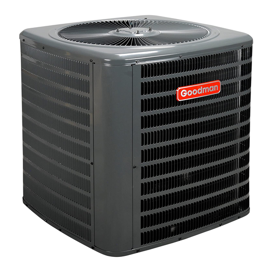
CONDENSING AC UNIT
3-PHASE 7.5 & 10 TON AIR CONDITIONER
INSTALLATION & SERVICE REFERENCE
NOTICE
THIS UNIT IS SHIPPED WITH A NITROGEN/HELIUM HOLDING CHARGE ONLY. UNIT
MUST BE EVACUATED AND CHARGED PER INSTALLATION INSTRUCTIONS WITH
REFRIGERANT LISTED ON SERIAL RATING PLATE.
NOTICE
UNITS SHIPPED WITH A HOLDING CHARGE ARE INTENDED FOR COMPONENT
REPLACEMENT ONLY ON EXISTING SYSTEMS, AND NOT INTENDED FOR USE IN
NEW SYSTEMS OR NEWLY CONSTRUCTED HOMES.
NOTICE
UNITS MUST ONLY BE USED AS REPLACEMENT COMPONENTS FOR PRE-2010
INSTALLED SYSTEMS.
Important Safety Instructions
The following symbols and labels are used throughout this
manual to indicate immediate or potential safety hazards. It is
the owner's and installer's responsibility to read and comply
with all safety information and instructions accompanying these
symbols. Failure to heed safety information increases the risk
of personal injury, property damage, and/or product damage.
WARNING
HIGH VOLTAGE!
Disconnect ALL power before servicing.
Multiple power sources may be present.
Failure to do so may cause property damage,
personal injury or death.
ONLY individuals meeting the requirements of an
"Entry Level Technician", at a minimum, as specified
by the Air Conditioning, Heating and Refrigeration
Institute (AHRI) may use this information. Attempting
to install or repair this unit without such background
may result in product damage, personal injury,
or death.
Shipping Inspection
Always keep the unit upright; laying the unit on its side or top
may cause equipment damage. Shipping damage, and subse-
quent investigation is the responsibility of the carrier. Verify
the model number, specifications, electrical characteristics,
and accessories are correct prior to installation. The distribu-
tor or manufacturer will not accept claims from dealers for trans-
portation damage or installation of incorrectly shipped units.
© 2010 Goodman Manufacturing Company, L.P.
5151 San Felipe, Suite 500, Houston, TX 77056
www.goodmanmfg.com -or- www.amana-hac.com
P/N: IO-404
Date: November 2010
Codes & Regulations
This product is designed and manufactured to comply with
national codes. Installation in accordance with such codes and/
or prevailing local codes/regulations is the responsibility of the
installer. The manufacturer assumes no responsibility for equip-
ment installed in violation of any codes or regulations.
The United States Environmental Protection Agency (EPA)
has issued various regulations regarding the introduc-
tion and disposal of refrigerants. Failure to follow these
regulations may harm the environment and can lead to
the imposition of substantial fines. Should you have any
questions please contact the local office of the EPA.
If replacing a condensing unit or air handler, the system must
be manufacturer approved and Air Conditioning, Heating and
Refrigeration Institute (AHRI) matched.
Refer to the unit Specification Sheet for the recommended in-
door model selection. NOTE: This unit must be used with a
purchased single stage room thermostat with 24 VAC control
circuitry.
Do not operate the unit in a structure that is not complete
(either as part of new construction or renovation). Such opera-
tion will void the warranty.
Installation Clearances
This unit is designed for outdoor installations only. Special
consideration must be given to location of the condensing unit(s)
in regard to structures, obstructions, other units, and any/all
other factors that may interfere with air circulation. Where
possible, the top of the unit should be completely unobstructed;
however, if vertical conditions require placement beneath an
obstruction there should be a minimum of 60 inches be-
tween the top of the unit and the obstruction(s). The speci-
fied dimensions meet requirements for air circulation only.
Consult all appropriate regulatory codes prior to determining
final clearances.
Advertisement
Table of Contents

Related Manuals for Goodman CONDENSING AC UNIT


Summary of Contents for Goodman CONDENSING AC UNIT
-
Page 1: Important Safety Instructions
CONDENSING AC UNIT © 2010 Goodman Manufacturing Company, L.P. 5151 San Felipe, Suite 500, Houston, TX 77056 3-PHASE 7.5 & 10 TON AIR CONDITIONER www.goodmanmfg.com -or- www.amana-hac.com INSTALLATION & SERVICE REFERENCE P/N: IO-404 Date: November 2010 NOTICE THIS UNIT IS SHIPPED WITH A NITROGEN/HELIUM HOLDING CHARGE ONLY. UNIT MUST BE EVACUATED AND CHARGED PER INSTALLATION INSTRUCTIONS WITH REFRIGERANT LISTED ON SERIAL RATING PLATE. -
Page 2: Rooftop Installations
Another important consideration in selecting a location for the unit(s) is the angle to obstructions. Either side adjacent the valves can be placed toward the structure provided the side away from the structure maintains minimum service clearance. Corner installations are strongly discouraged. 12"... -
Page 3: Refrigerant Lines
WARNING To avoid possible explosion, use only returnable (not disposable) service cylinders when removing refrig- erant from a system. • Ensure the cylinder is free of damage which could lead to a leak or explosion. • Ensure the hydrostatic test date does not exceed 5 years. - Page 4 Refrigerant Line Connections Pressure test the system using dry nitrogen and soapy water to locate leaks. If you wish to use a leak detector, charge the system to 10 psi using the appropriate refrigerant then use NOTICE nitrogen to finish charging the system to working pressure then THIS UNIT IS SHIPPED WITH A NITROGEN/HELIUM apply the detector to suspect areas.
-
Page 5: Electrical Connections
RATED MINIMUM SUPPLY MAXIMUM SUPPLY 5000 VOLTAGE VOLTAGE VOLTAGE 4500 208/230V 4000 460V LEAK(S) 3500 PRESENT The condensing unit rating plate lists pertinent electrical data 3000 necessary for proper electrical service and overcurrent protec- 2500 tion. Wires should be sized to limit voltage drop to 2% (max.) 2000 from the main breaker or fuse panel to the condensing unit. -
Page 6: High Voltage Connections
To correct, disconnect power and switch any two leads at the Example: unit contactor and re-observe. A 7 ½ Ton unit is to be installed. The distance from the building to the unit is 75’. Calculate the minimum wire size High Voltage Connections assuming no more than 2% voltage drop. - Page 7 For the 7-1/2 ton unit starting charge should be 15 lb of R-22 If subcooling and superheat are high, adjust TXV and 18 lbs for the 10 ton unit. The length of line set, indoor unit valve to 9 ± 1 ºF superheat, then check subcooling. airflow, condensing unit location and number of tubing fittings If subcooling is high and superheat is low, adjust will have an impact on final unit charge amount.
-
Page 8: Troubleshooting
TROUBLESHOOTING ANALYSIS TABLE COMPLAINT PROBABLE CAUSE REMEDY 1. Excessive charge of refrigerant in system. 1. Purge or pump-down excessive charge. 2. Inadequate supply of air across the 2. Make certain that coil is not fouled in any 1. High Head Pressure condenser coil.
Need help?
Do you have a question about the CONDENSING AC UNIT and is the answer not in the manual?
Questions and answers