Advertisement
•
Refer to Service Manual RS6200006 for installation, operation, and troubleshooting information.
•
All safety information must be followed as provided in the Service Manual.
•
Refer to the appropriate Parts Catalog for part number information.
•
Models listed on page 3.
This manual is to be used by qualified, professionally trained HVAC technicians only. Goodman does not
assume any responsibility for property damage or personal injury due to improper service procedures
or services performed by an unqualified person.
TECHNICAL MANU
TECHNICAL MANU
TECHNICAL MANU AL
TECHNICAL MANU
TECHNICAL MANU
®
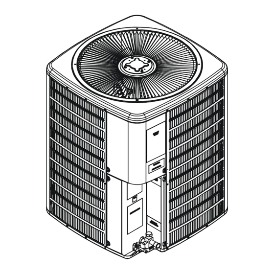
SSX 14 SEER
Condensing Units
Copyright © 2006-2012 Goodman Manufacturing Company, L.P.
AL
AL
AL
AL
RT6113003r11
January 2012
Advertisement
Table of Contents

Related Manuals for Goodman SSX 14 SEER


Summary of Contents for Goodman SSX 14 SEER
-
Page 1: Condensing Units
Refer to the appropriate Parts Catalog for part number information. • Models listed on page 3. This manual is to be used by qualified, professionally trained HVAC technicians only. Goodman does not RT6113003r11 assume any responsibility for property damage or personal injury due to improper service procedures January 2012 or services performed by an unqualified person. -
Page 2: Product Identification
Disconnect ALL power before servicing or installing this unit. Multiple power sources may be present. Failure to do so may cause property damage, personal injury or death. ONLY individuals meeting (at a Goodman will not be responsible WARNING WARNING WARNING... - Page 3 WARNING that is not design certified by damage, personal injury, or death, Goodman for use with this unit. do not store combustible materials or use gasoline or Serious property damage, personal injury, reduced unit other flammable liquids or vapors in the vicinity of this performance and/or hazardous conditions may result appliance.
-
Page 4: Product Design
PRODUCT DESIGN SSX14 models are available in 1 1/2 through 5 ton sizes and minimum of 60 inches between the top of the unit and use R-410A refrigerant. They are designed for 208/230 volt the obstruction(s). The specified dimensions meet require- single phase applications. - Page 5 PRODUCT DESIGN DIMENSIONS SSX140**1* Model Dimensions - W x D x H SSX140181A* 26" x 26" x 32¼" SSX140181B* 26" x 26" x 27½" SSX140241A* 26" x 26" x 32½" SSX140241B* 26" x 26" x 32½" SSX140301A* 29" x 29" x 32¼" SSX140301B* 29"...
- Page 6 CONDENSING UNIT SPECIFICATIONS SSX140181A* - SSX140361A* SSX14018 SSX14018 SSX14024 SSX140241 SSX140301 SSX140301 SSX140361 SSX140361 AA/AB AA/AB AA/AB/AC AD/AE AA/AB/AC AD/AE Cooling Capacity, BTUH 18,000 18,000 24,000 24,000 30,000 30,000 36,000 36,000 Compressor R.L. Amps 9.00 9.00 13.4 13.4 12.8 12.8 14.1 14.1 L.R.
- Page 7 CONDENSING UNIT SPECIFICATIONS SSX140[18-48]1B* SSX140181 SSX140241 SSX140301 SSX140361 SSX140361 SSX140421 SSX140481 Cooling Capacity, BTUH 18,000 24,000 28,800 34,600 34,600 40,000 46,000 Compressor R.L. Amps 9.00 13.4 12.8 14.1 14.1 17.9 19.9 L.R. Amps 48.0 58.3 64.0 77.0 77.0 112.0 109.0 Low Pressure Switch Open 22 PSIG...
- Page 8 COOLING PERFORMANCE DATA SSX140181A*...
- Page 9 COOLING PERFORMANCE DATA SSX140181A*...
- Page 10 COOLING PERFORMANCE DATA SSX140181B*...
- Page 11 COOLING PERFORMANCE DATA SSX140181B*...
- Page 12 COOLING PERFORMANCE DATA SSX140241A*...
- Page 13 COOLING PERFORMANCE DATA SSX140241A*...
- Page 14 COOLING PERFORMANCE DATA SSX140241B*...
- Page 15 COOLING PERFORMANCE DATA SSX140241B*...
- Page 16 COOLING PERFORMANCE DATA SSX140301A*...
- Page 17 COOLING PERFORMANCE DATA SSX140301A*...
- Page 18 SSX140301B* COOLING PERFORMANCE DATA...
- Page 19 COOLING PERFORMANCE DATA SSX140301B*...
- Page 20 COOLING PERFORMANCE DATA SSX140361A*...
- Page 21 COOLING PERFORMANCE DATA SSX140361A*...
- Page 22 COOLING PERFORMANCE DATA SSX140361B*...
- Page 23 COOLING PERFORMANCE DATA SSX140361B*...
- Page 24 COOLING PERFORMANCE DATA SSX140421A*...
- Page 25 COOLING PERFORMANCE DATA SSX140421A*...
- Page 26 COOLING PERFORMANCE DATA SSX140421B*...
- Page 27 COOLING PERFORMANCE DATA SSX140421B*...
- Page 28 SSX140421C* COOLING PERFORMANCE DATA...
- Page 29 COOLING PERFORMANCE DATA SSX140421C*...
- Page 30 COOLING PERFORMANCE DATA SSX140481A*...
- Page 31 COOLING PERFORMANCE DATA SSX140481A*...
- Page 32 SSX140481B* COOLING PERFORMANCE DATA...
- Page 33 COOLING PERFORMANCE DATA SSX140481B*...
- Page 34 COOLING PERFORMANCE DATA SSX140601A*...
- Page 35 COOLING PERFORMANCE DATA SSX140601A*...
-
Page 36: Performance Data
PERFORMANCE DATA SSX140[18-60]1A* MODEL: SSX140181A* / CA*F3131B6A* + TXV MODEL: SSX140241A* / CA*F3636B6A* W/.057 Orifice, Conditions: 80°F IDB, 67°F IWB @ 600 CFM Conditions: 80°F IDB, 67°F IWB @ 800 CFM Outdoor Total Sensible Latent Total Outdoor Total Sensible Latent Total Temp. - Page 37 PERFORMANCE DATA SSX14[18-48]1B* MODEL: SSX140241B* / CA*F3636*6C* W/.055 Orifice, MODEL: SSX140181B* / CA*F3636*6C* W/.052 Orifice Conditions: 80°F IDB, 67°F IWB @ 725 CFM Conditions: 80°F IDB, 67°F IWB @ 600 CFM Outdoor Total Sensible Latent Total Outdoor Total Sensible Latent Total Temp.
- Page 38 PERFORMANCE DATA SSX140421C* MODEL: SSX140421C* / CA*F4860*6B* W/.070 Orifice, Conditions: 80°F IDB, 67°F IWB @ 1450 CFM Outdoor Total Sensible Latent Total Temp. ° F. Btuh Btuh Btuh Watts 75° 42,116 29,985 12,131 2,950 80° 41,614 30,004 11,610 3,040 85° 41,113 30,015 11,098...
-
Page 39: Wiring Diagrams
WIRING DIAGRAMS SSX140[18-60]1A*/BA HIGH VOLTAGE! DISCONNECT ALL POWER BEFORE SERVICING OR INSTALLING THIS UNIT. MULTIPLE POWER SOURCES MAY BE PRESENT. FAILURE TO DO SO MAY CAUSE PROPERTY DAMAGE, PERSONAL INJURY OR DEATH. Wiring is subject to change, always refer to the wiring diagram on the unit for the most up-to-date wiring. - Page 40 WIRING DIAGRAMS SSX140[18-60]BB HIGH VOLTAGE! DISCONNECT ALL POWER BEFORE SERVICING OR INSTALLING THIS UNIT. MULTIPLE POWER SOURCES MAY BE PRESENT. FAILURE TO DO SO MAY CAUSE PROPERTY DAMAGE, PERSONAL INJURY OR DEATH. Wiring is subject to change, always refer to the wiring diagram on the unit for the most up-to-date wiring.
Need help?
Do you have a question about the SSX 14 SEER and is the answer not in the manual?
Questions and answers