
Related Manuals for Friedrich D30C


Summary of Contents for Friedrich D30C
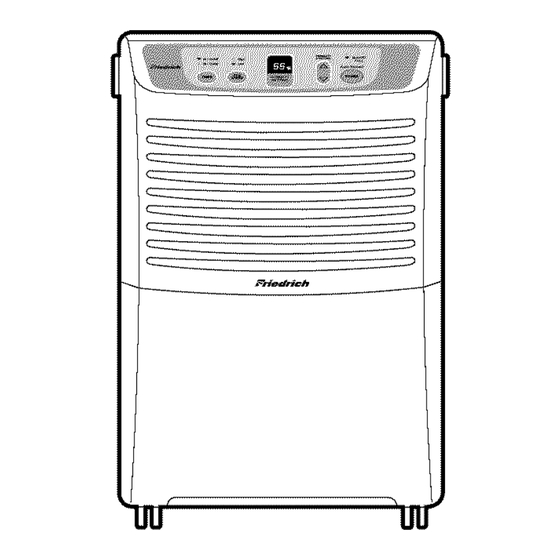
- Page 1 Dehumidifier S ervic e and Parts Manual D30C D40C D50C D65C DehumSvcParts (06/05)
-
Page 2: Table Of Contents
CONTENTS 1. PREFACE 1.1 SAFETY PRECAUTIONS ...........................3 1.2 FEATURES AND DIMENSIONS ........................3 1.2.1 FEATURES............................3 1.2.2 DIMENSIONS ............................3 1.3 SPECIFICATIONS ............................4 1.4 CONTROL TYPE ............................4 2. CIRCUIT DIAGRAM ..........................5~6 3. DISASSEMBLY INSTRUCTIONS 3.1 MECHANICAL PARTS ..........................7 3.1.1 BUCKET AND AIR FILTER .......................7 3.1.2 FRONT CASE AND REAR GRILLE....................7 3.1.3 CABINET AND CONTROL BOX .......................7 3.2 CONTROL PARTS ............................8... -
Page 3: Preface
1. PREFACE This Service Manual provides various service information, including the mechanical and electrical parts. This dehumidifier was manufactured and assembled under the strict quality control procedures. The refrigerant is charged at the factory. Be sure to read the safety precaution prior to servicing the unit. 1.1 SAFETY PRECAUTIONS •... -
Page 4: Specifications
1.3 SPECIFICATIONS MODELS D30C D40C D50C D65C ITEMS CAPACITY(Pints/24hrs) POWER SUPPLY(Phase,V,Hz) 1Ø, 115V,60Hz INPUT(W) RUNNING CURRENT(A) ENERGY FACTOR(L/kw.h) 1.23 1.36 1.75 1.50 REFRIGERANT REFRIGERANT CHARGE, oz(g) 3.53(100) 4.94(140) 7.93(225) 8.46(240) OPEN 33.8°F(1±0.5°C) THERMISTOR CLOSE 50°F(10±0.5°C) COMPRESSOR MODEL No. QS064CAB QS075CBA... -
Page 5: Circuit Diagram
2. CIRCUIT DIAGRAM • MODEL : D30C Q'TY DESCRIPTION PER SET MARKS POWER CORD ASSEMBLY MOTOR ASSEMBLY CAPACITOR COMPRESSOR, SET PWB(PCB) ASSEMBLY, DISPLAY SENSOR ASSEMBLY SWITCH ASSEMBLY, MICRO PWB(PCB) ASSEMBLY, MAIN S: SERVICE PARTS A: ALTERNATE PARTS N: NOT SERVICE PARTS... - Page 6 • MODEL : D40C / D50C / D65C Q'TY DESCRIPTION PER SET MARKS POWER CORD ASSEMBLY MOTOR ASSEMBLY CAPACITOR COMPRESSORT,SET PWB(PCB)ASSEMBLY,DISPLAY SENSOR ASSEMBLY SWITCH ASSEMBLY,MICRO PWB(PCB)0ASSEMBLY,MAIN S: SERVICE PARTS A: ALTERNATE PARTS N: NOT SERVICE PARTS —6—...
-
Page 7: Disassembly Instructions
3. DISASSEMBLY INSTRUCTIONS 3.1 MECHANICAL PARTS 3.1.1 BUCKET AND AIR FILTER 1. Press the power button off. 2. Disconnect the power supply. 3. Remove the bucket. (See Figure 3) 4. Pull out the air filter. (See Figure 4) Figure 3 Figure 4 3.1.2 FRONT CASE AND REAR GRILLE 1. -
Page 8: Control Parts
3.2 CONTROL PARTS 3.2.1 POWER CORD ASSEMBLY 1. After opening the control box, remove the screw that holds the ground wire. (See Figure 9) 2. Disconnect the remaining leads of the power cord from the PWB(PCB) ASSEMBLY, MAIN, then remove it from the control box. Figure 9 3.2.2 SENSOR ASSEMBLY 1. -
Page 9: Control Panel
3.2.6 CONTROL PANEL 1. Disconnect the housing of the PWB(PCB) ASSEMBLY, DISPLAY from PWB(PCB) ASSEMBLY, MAIN . 2. Remove 6 screws that fasten the PWB(PCB) ASSEMBLY, DISPLAY to the display cover. (See Figure 13) Figure 13 3.2.7 FAN AND MOTOR 1. -
Page 10: Shroud And Drain Pan
3.2.8 SHROUD AND DRAIN PAN 1. Discharge the refrigerant by using a refrigerant Recovery System. 2. After purging the unit completely, unbrace the Discharge and the Suction tube connected to the compressor. 3. Remove 2 screws that fasten the heat exchanger. 4. -
Page 11: Refrigerating System
3.3 REFRIGERATION SYSTEM 3.3.1 CONDENSER, EVAPORATOR AND CAPILLARY TUBE 1. Remove the insulation on the condenser/evaporator (H/E) assembly 2. Pierce the pinch-off tube to discharge the refrigerant, using a refrigerant recovery system. 3. After discharging the refrigerant completely, remove 2 screws between the shroud and the H/E. -
Page 12: How To Replace Refrigeration System
3.4 HOW TO REPLACE THE REFRIGERATION SYSTEM 1. When replacing a refrigeration component, be sure 7. Recharge as follows : to discharge the refrigerant system by using a 1) Refrigeration cycle systems are charged from the refrigerant recovery system. High-side. If the total charge cannot be put 2. - Page 13 Equipment needed: Vacuum pump, charging cylinder, manifold gauge, brazing equipment. pinch-off tool capable of making a vapor-proof seal, leak detector, tubing cutter, hand tools to remove components, service valve. EVAPORATOR ASSEMBLY (LOW PRESSURE SIDE) CONDENSER ASSEMBLY (HIGH PRESSURE SIDE) COMPOUND GAUGE MANIFOLD GAUGE CAPILLARY...
-
Page 14: Troubleshooting Guide
4. TROUBLESHOOTING GUIDE CONDITION CAUSE REMEDY 1. Dehumidifier does not start. (Both No power Check power supply at outlet. compressor and fan motor do not Correct if none. operate.) Poor plug contact at outlet. Install plug properly or replace it. Bucket is full. - Page 15 CONDITION CAUSE REMEDY 5. Noisy operation If cracked, out of balance, or partially missing, replace it Loose foreign material inside the housing. Remove it. Tube hits frame. Adjust tubing routine carefully. Fan blade hits frame Check Motor Mount. If loose, tighten it. Internal compressor noise.
-
Page 16: Exploded Views
5. EXPLODED VIEWS • MODEL: D30C W0CZZ 149980 349600 554030 354210 268714 359012 264110 249950 346811 435300 130900 162615 135312 238310 268712 436500 352113 35211A 152302 266011 552111 752140 330870 567502 130411 554160 144410 148390 550140 —16—... - Page 17 • MODEL: D40C 149980 W0CZZ 349600 554030 354210 359012 268714 249950 346811 435300 264110 130900 162615 135312 238310 268712 436500 352113 35211A 152302 266011 552111 752140 330870 567502 130401 554160 144410 148390 550140 —17—...
- Page 18 • MODEL: D50C 149980 W0CZZ 349600 554030 354210 359012 268714 249950 346811 435300 264110 130900 162615 135312 238310 268712 436500 352113 35211A 152302 266011 552111 752140 330870 567502 130401 554160 144410 148390 550140 —18—...
- Page 19 • MODEL: D65C 149980 W0CZZ 349600 554030 354210 359012 268714 249950 346811 435300 264110 130900 162615 135312 238310 268712 436500 352113 35211A 152302 266011 552111 752140 330870 567502 130401 554160 144410 550140 148390 —19—...
-
Page 20: Replacement Parts List
6. REPLACEMENT PARTS LIST • MODEL: D30C PART NO. LOCATION DESCRIPTION D30C 130411 BASE ASSEMBLY 67500072 130900 CABINET 67400185 135312 FRONT GRILLE,ASSEMBLY 67306010 330870 DRAIN PAN ASSEMBLY 67500126 148390 TANK ASSEMBLY,BUCKET 67500083 152302 FILTER(MECH),AIR 67500098 162615 SENSOR ASEMBLY 67500099 249950... - Page 21 • MODEL: D40C PART NO. LOCATION DESCRIPTION D40C 130411 BASE ASSEMBLY 67500071 130900 CABINET 67400185 135312 FRONT GRILLE,ASSEMBLY 67306010 330870 DRAIN PAN ASSEMBLY 67500126 148390 TANK ASSEMBLY,BUCKET 67500083 152302 FILTER(MECH),AIR 67500098 162615 SENSOR ASEMBLY 67500093 W0CZZ CAPACITOR 67400182 249950 CONTROL BOX,ASSEMBLY 67500084 264110 POWER CORD,ASSEMBLY...
- Page 22 • MODEL: D50C PART NO. LOCATION DESCRIPTION D50C 130411 BASE ASSEMBLY 67500072 130900 CABINET 67400185 135312 FRONT GRILLE,ASSEMBLY 67306010 330870 DRAIN PAN ASSEMBLY 67500126 148390 TANK ASSEMBLY,BUCKET 67500083 152302 FILTER(MECH),AIR 67500098 162615 SENSOR ASEMBLY 67500099 W0CZZ CAPACITOR 67400184 249950 CONTROL BOX,ASSEMBLY 67500127 264110 POWER CORD,ASSEMBLY...
- Page 23 • MODEL: D65C PART NO. LOCATION DESCRIPTION D65C 130411 BASE ASSEMBLY 67500072 130900 CABINET 67400185 135312 FRONT GRILLE,ASSEMBLY 67306010 330870 DRAIN PAN ASSEMBLY 67500126 148390 TANK ASSEMBLY,BUCKET 67500083 152302 FILTER(MECH),AIR 67500098 162615 SENSOR ASEMBLY 67500099 W0CZZ CAPACITOR 67400184 249950 CONTROL BOX,ASSEMBLY 67500086 264110 POWER CORD,ASSEMBLY...
- Page 24 F R IE DR IC H AIR C ONDIT IONING C O. V is it our web s ite at www.friedrich.com P os t Office B ox 1540 • 4200 N. P an Am E xpres s way • S an Antonio, T exas 78295-1540...
Need help?
Do you have a question about the D30C and is the answer not in the manual?
Questions and answers