
Related Manuals for Friedrich D30A


Summary of Contents for Friedrich D30A
- Page 1 Dehumidifier Service and Parts Manual D30A D40A D50A D65A D30A / D40A / D50A / D65A (03/03)
-
Page 2: Table Of Contents
CONTENTS 1. PREFACE 1.1 SAFETY PRECAUTIONS ...........................3 1.2 FEATURES AND DIMENSIONS ........................3 1.2.1 FEATURES............................3 1.2.2 DIMENSIONS ............................3 1.3 SPECIFICATIONS ............................4 1.4 CONTROL ..............................5 1.5 HOW TO OPERATE DEHUMIDIFIER ......................6 1.5.1 HOW DOES THE DEHUMIDIFIER WORK? ..................6 1.5.2 LOCATION FOR THE DEHUMIDIFIER.....................6 1.5.3 MICRO SWITCH..........................6 1.5.4 AUTO DEFROST..........................6 1.5.5 HUMIDITY CONTROLLER........................7... -
Page 3: Preface
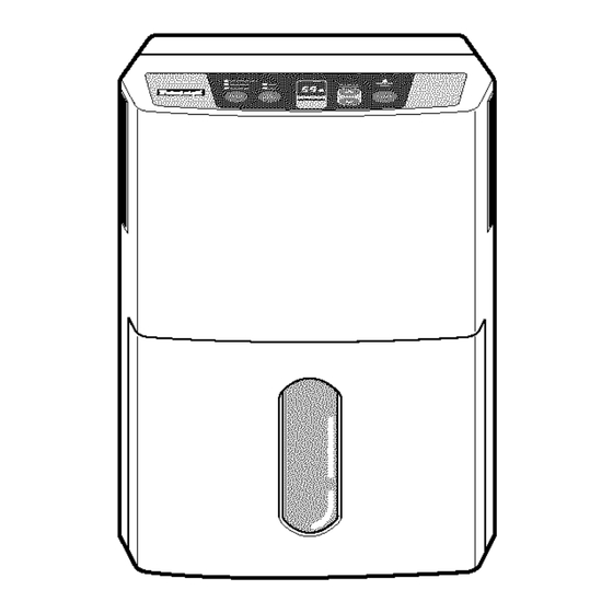
340 (13 Continuous On. 4Hr. On/Off High HUMIDITY BUCKET CONTROL FULL 2Hr. On/Off F AN TIMER SPEED POWER Continuous On. BUCKET 4Hr. On/Off High HUMIDITY CONTROL FULL 2Hr. On/Off TIMER SPEED F AN POWER D30A/D40A Model D50A/D65A Model Figure 1 —3—... -
Page 4: Specifications
1.3 SPECIFICATIONS MODELS D30A D40A D50A D65A ITEMS CAPACITY (Pints/24hrs) POWER SUPPLY (Phase, V, Hz) 1ø, 115V, 60Hz REFRIGERANT R134a REFRIGERANT CHARGE, oz(g) 5.47(155) 5.64(160) 7.23(205) 7.76(220) OPEN 30.2°F(-1 ±0.5°C) 32.9°F(0.5 ±0.5°C) 30.2°F(-1 ±0.5°C) THERMISTOR CLOSE 50.0°F(10 ±0.5°C) 53.6°F(12 ±0.5°C) 50.0°F(10 ±0.5°C) -
Page 5: Control
1.4 CONTROL Continuous BUCKET HUMIDITY 4Hr. On/Off High FULL CONTROL 2Hr. On/Off TIMER POWER SPEED Figure 2 Bucket Full Indicator Fan Speed • This light glows when the water bucket is • This controls the speed of the airflow. full and needs to be emptied. •... -
Page 6: How To Operate Dehumidifier
1.5 HOW TO OPERATE DEHUMIDIFIER 1.5.1 HOW DOES THE DEHUMIDIFIER WORK? Condenser Moist, humid air is drawn over a cold refrigerated Motor Evaporator dehumidifying coil. Moisture in the air condenses on this coil and drains into a bucket (or through the bucket into a Humid hose and drain). -
Page 7: Humidity Controller
Press the Power button to stop the unit manually. Figure 5 1.5.6 DRIER (D30A) Dryer is used to prevent capillary blockage from moisture in the refrigerant system and H/E, condenser and evaporator. Also, dryer is used to remove corrosion of the components. -
Page 8: Circuit Diagram
2. CIRCUIT DIAGRAM • MODEL : D30A MAIN PCB CN-FAN BK(HI) RD(LOW) MOTOR OR(COM) GN/YL CN-AC1 WH(BL) (N) BUCKET CN-AC2 CN-SEN HUMIDITY GN/YL SENSOR POWER RY-COMP COMP. TRANS THERMISTOR FUSE 250V T3.15A O.L.P BK(BR) (L) WIRING DIAGRAM 3854A20247E PART NO. -
Page 9: Wiring Diagram
• MODEL : D40A/D50A/D65A MAIN PCB CN-FAN BK(HI) RD(LOW) MOTOR OR(COM) GN/YL CN-AC1 WH(BL) (N) BUCKET CN-AC2 CN-SEN HUMIDITY GN/YL SENSOR POWER COMP. RY-COMP TRANS THERMISTOR FUSE 250V T3.15A O.L.P BK(BR) (L) WIRING DIAGRAM 3854A20247F PART NO. LOCATION Q'TY DESCRIPTION PER SET MARKS D40A... -
Page 10: Disassembly Instructions
3. DISASSEMBLY INSTRUCTIONS 3.1 MECHANICAL PARTS 3.1.1 BUCKET AND AIR FILTER 1. Disconnect the power supply. 2. Press the power button off. 3. Remove the bucket. (See Figure 7) 4. Pressing the hooks, pull out the air filter. (See Figure 8) Figure 7 Figure 8 3.1.2 FRONT CASE AND TOP COVER... -
Page 11: Control Parts
ASSEMBLY, MAIN and pull it out after unhooking from 2 rectangular holes of control box (lower). (See Figure 15) 3.2.4 CAPACITOR (Except D30A) Figure 15 1. Remove a screw that fastens capacitor. (See Figure 15) 2. Disconnect all leads of capacitor then remove it from control box. -
Page 12: Control Panel
3.2.6 CONTROL PANEL 1. Disconnect housing of PWB(PCB) ASSEMBLY, DISPLAY from PWB(PCB) ASSEMBLY, MAIN (3.1.3). 2. Remove 5 screws that secure the PWB(PCB) ASSEMBLY, DISPLAY to cover display. Figure 17 3.2.7 HOUSING ASSEMBLY, FAN AND MOTOR 1. Remove 4 screws that fasten the housing assembly to heat exchanger and drain pan, and lift housing assembly upward after unhooking 2 hooks on the housing. -
Page 13: Drain Pan
(See Figure 24) 3.3.2 P.T.C. OR OVERLOAD PROTECTOR (O.L.P.) FOR RECIPROCATING COMPRESSOR Figure 24 (D30A) 1. Discharge the refrigerant by using a refrigerant Recovery System. 2. After purging the unit completely, unbrace the suction and discharge tubes at the compressor connections. -
Page 14: How To Replace Refrigeration System
3.4 HOW TO REPLACE THE REFRIGERATION SYSTEM 1. When replacing the refrigeration cycle, be sure to 7. Recharge as follows : discharge the refrigerant system by using a 1) Refrigeration cycle systems are charged from the refrigerant recovery system. High-side. If the total charge cannot be put 2. - Page 15 Equipment needed: Vacuum pump, charging cylinder, manifold gauge, brazing equipment. pinch-off tool capable of making a vapor-proof seal, leak detector, tubing cutter, hand tools to remove components, service valve. EVAPORATOR ASSEMBLY EVAPORATOR ASSEMBLY (LOW PRESSURE SIDE) (LOW PRESSURE SIDE) CONDENSER ASSEMBLY CONDENSER ASSEMBLY (HIGH PRESSURE SIDE) (HIGH PRESSURE SIDE)
-
Page 16: Troubleshooting Guide
4. TROUBLESHOOTING GUIDE Problem Possible Causes Remedy Dehumidifier does not start. The dehumidifier is unplugged. Make sure the dehumidifier's plug is pushed completely into the outlet. The fuse is blown/circuit Check the house fuse/circuit breaker breaker is tripped. box and replace the fuse or reset the breaker. - Page 17 CONDITION CAUSE REMEDY 1. Dehumidifier does not start. (Both No power Check power supply at outlet. compressor and fan motor do not Correct if none. operate.) Poor plug contact at outlet. Install plug properly or replace it. Bucket is full. If Auto Shut Off lights, empty the bucket and replace properly.
- Page 18 CONDITION CAUSE REMEDY 5. Noisy operating If cracked, out of balance, or partially missing, replace it Some material plunged and rattle. Remove it. Tube hits frame. Adjust tubing routine carefully. Fan blade hits frame Check Motor Mount. If loose, tighten it. Internal compressor noise.
-
Page 19: Exploded View - Introduction
5. EXPLODED VIEW - INTRODUCTION • MODEL: D30A 35211A 352113 268714 264110 249950 354210 558511 552111 349480 346811 336610 359012 554030 336600 349600 667482 550140 554160 567502 162615 235512 135500 436500 330870 238310 268712 148380 266011 130910 144410 131110 130411 152302 —19—... - Page 20 • MODEL: D40A W0CZZ 35211A 352113 264110 249950 354210 268714 554160 349480 346811 336610 359012 567502 554030 336600 552111 349600 550140 162615 235512 135500 436500 330870 238310 268712 148380 266011 130910 144410 131110 130411 152302 —20—...
- Page 21 • MODEL: D50A W0CZZ 352111 35211A 264110 249950 354210 268714 552113 349480 346811 336610 359012 567502 554030 336600 349600 554160 550140 162615 235512 135500 436500 330870 238310 268712 148380 266011 130910 144410 131110 130411 152302 —21—...
- Page 22 • MODEL: D65A W0CZZ 264110 249950 552111 35211A 354210 268714 352113 349480 346811 336610 359012 567502 554030 336600 349600 554160 550140 162615 235512 135500 330870 436500 238310 268712 148380 266011 130910 144410 131110 130411 152302 —22—...
-
Page 23: Replacement Parts List
6. REPLACEMENT PARTS LIST • MODEL: D30A PART NO. LOCATION DESCRIPTION REMARK D30A 130411 BASE ASSEMBLY, SELD(SINGLE) 3041A10028C 130910 CABINET ASSEMBLY, SINGLE 3091A20015D 131110 CASE ASSEMBLY, SINGLE 3111A10016F 330870 DRAIN PAN ASSEMBLY 3087A10011B 148380 TANK, ASSEMBLY, BUCKET 4839A10001D 152302 FILTER(MECH), AIR... - Page 24 • MODEL: D40A PART NO. LOCATION DESCRIPTION REMARK D40A 130411 BASE ASSEMBLY, WELD(SINGLE) 3041A10028A 130910 CABINET ASSEMBLY, SINGLE 3091A20015B 131100 CASE ASSEMBLY, SINGLE 3111A10016B 330870 DRAIN PAN ASSEMBLY 3087A10011A 148380 TANK ASSEMBLY, BUCKET 4839A10001D 152302 FILTER(MECH), AIR 5230A20026A 162615 SENSOR ASSEMBLY 6877A30013H W0CZZ CAPACITOR...
- Page 25 • MODEL: D50A PART NO. LOCATION DESCRIPTION REMARK D50A 130411 BASE ASSEMBLY, WELD(SINGLE) 3041A10028B 130910 CABINET ASSEMBLY, SINGLE 3091A20015F 131110 CASE ASSEMBLY, SINGLE 3111A10016C 330870 DRAIN PAN ASSEMBLY 3087A10011C 148380 TANK ASSEMBLY, BUCKET 4839A10001E 152302 FILTER(MECH), AIR 5230A20026A 162615 SENSOR ASSEMBLY 6877A30013H W0CZZ CAPACITOR...
- Page 26 • MODEL: D65A PART NO. LOCATION DESCRIPTION REMARK D65A 130411 BASE ASSEMBLY, WELD(SINGLE) 3041A10028B 130910 CABINET ASSEMBLY, SINGLE 3091A20015F 131110 CASE ASSEMBLY, SINGLE 3111A10016C 330870 DRAIN PAN ASSEMBLY 3087A10011C 148380 TANK ASSEMBLY, BUCKET 4839A10001E 152302 FILTER(MECH), AIR 5230A20026A 162615 SENSOR ASSEMBLY 6877A30013H W0CZZ CAPACITOR...
- Page 27 Visit our web site at www.friedrich.com Post Office Box 1540 • 4200 N. Pan Am Expressway • San Antonio, Texas 78295-1540 • (210) 357-4400 • FAX (210) 357-4480 P/NO.:3828A20090N Printed in the U.S.A D30A / D40A / D50 / 65A (03/03)
Need help?
Do you have a question about the D30A and is the answer not in the manual?
Questions and answers