Table of Contents
Advertisement
Advertisement
Table of Contents

Related Manuals for ZMODO DVR


Summary of Contents for ZMODO DVR
-
Page 2: Table Of Contents
.............................. 10 OWER UPPLY CONNECTION CHAPTER 4: DVR BOOT UP ............................... 11 ................................ 11 YSTEM NITIALIZATION ................................... 11 IVE SCREEN CHAPTER 5: DVR MENU............................. 11 .................................. 11 ‐ UP ................................ 12 AIN ENU UIDE .................................. 13 ... - Page 3 User Manual 5.3.5.1 Network ..................................... 2 0 5.3.4.2 Router’s Port Forwarding .............................. 2 2 5.3.4.3 Email set .................................... 2 2 5.3.4.4 Mobile Set .................................. 2 3 5.3.4.5 NTP function .................................. 2 4 5.3.6 Device Management.............................. 24 ...
- Page 4 User Manual 6.3.3. 7 Advanced .................................... 4 6 Local setting 6.3.4 ................................. 48 Logout 6.3.5 .................................. 48 CHAPTER 7: SPECIFICATION ............................. 49 CHAPTER 8: APPENDIX .............................. 50 .............................. 50 PERATION UNCTION ABLE ................................ 51 ECORD ...
-
Page 5: Safety Instruction
User Manual Safety Instruction 1. Read Instruction All the safety and operating instruction should be read before the equipment is operated. 2. Power sources This equipment should be operated only from the type of power source indicated on the marking label. If you are not sure of the type of power, please consult your equipment dealer. -
Page 6: Chapter 1 Features
Playback Support DVR single CH and multiple CH Search/Playback of recorded files. Backup Support DVR backup via USB flash drive, removable drive, Recorder and network. Alarm Setting Supports HDD & video input alarm management and external alarm signal inputs. Network operation Supports remote surveillance by authority users to increase system security. -
Page 7: Chapter 2: Overview
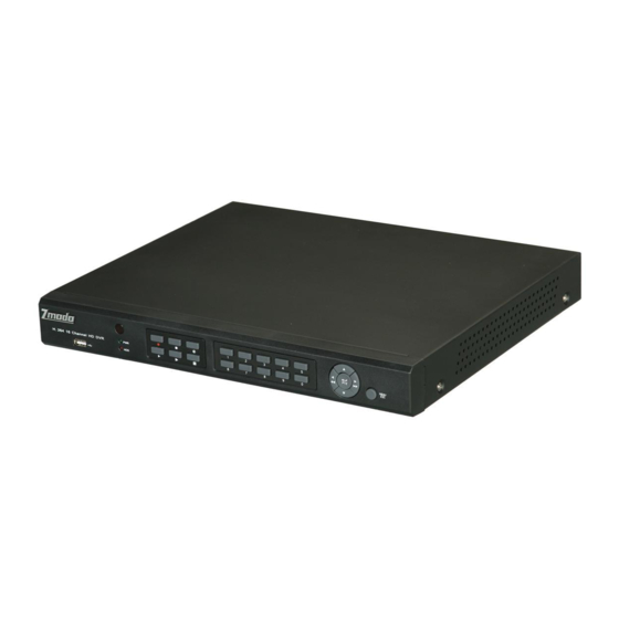
User Manual Chapter 2: Overview 2.1 16-CH DVR Front Panel Key title Item Type Marks Function /Indicator When the “Red” indicator flashes it means the hard drive is being HDD indicator read or written to. Indicator If the “Green” indicator is on the system is getting power Power indicator normally. -
Page 8: 16-Ch Dvr Rear Panel
User Manual 2.2 16-CH DVR Rear Panel Physical port Connection method Video input Connect CH1-16 (Virtual) video input(BNC interface) Video output Connect monitor output(BNC interface) Audio input Connect CH1-4 audio signal input (BNC interface) Audio output 2CH output; BNC (interface)... -
Page 9: Remote Controller
User Manual 2.3 Remote Controller Key Title Key Function Press the button to enter into manual record. SEARCH Press the button to enter into record search menu Enter into Quad display 2×2 Enter into 9-split display 3×3 Enter into 16-split display 4×4 Enter into dwell time display AUTO... - Page 10 User Manual Except using buttons of front panel or remote controller, you also can use mouse to perform system operation. TYPE Function In menu lock mode, Enter into pop-up menu and clicking any sub menu to pop up Log-in window; on menu unlock mode, enter into pop-up menu, and then clicking left key to enter into any sub menu directly.
-
Page 11: Chapter 3 Dvr Installation
(4) Put the upper cover back carefully, re-attach screws. 3.2 Camera and Monitor Connection Connect camera cable to video input of DVR, and from video output of DVR to Monitor via BNC connector (Refer to section2.2-Rear Panel); or If the camera is a PTZ speed dome, you could connect RS485 A & B to the according port of DVR respectively (refer to system figuration on Chapter 8). -
Page 12: Chapter 4: Dvr Boot Up
User Manual Chapter 4: DVR Boot up 4.1 System Initialization After connecting the Power cable of DVR to wall outlet and pressing the Power button on the front panel, you will enter into the system initializing screen shown as Picture 4-1... -
Page 13: Main Menu Guide
User Manual 5.2 Main Menu Guide Live set Display Output set Privacy Zone Main Stream Encode Sub stream Rec. Parameter Record Rec. Schedule Rec. Search Search Event Search Log Search Main Menu Network set DDNS set Network Email set 3G set Device Alarm Serial No... -
Page 14: Main Menu
User Manual 5.3 Main Menu On preview mode, click [Menu] button on the front panel or Remote controller to enter into Main menu interface shown as Picture 5-2. And also you can click ] icon to enter the main menu screen. In Main Menu mode, you can control device management settings, such as Display, Record, Network, Search, Device and System setting etc. -
Page 15: Output Mode
Transparency: transparency, and its range is 1~128. Margin: allow you adjust the whole screen’s margin. Details operations please refer to the Picture 5-6. Volume: allow you adjust the DVR volume shown as Picture 5-7. Picture 5-5 Picture 5-6 Picture 5-7 5.3.1.3 Privacy Zone... -
Page 16: Encode
User Manual 5.3.2 Encode 5.3.2.1 Main Stream set Go to [Main menu Encode Main Stream] to enter into the interface shown as Picture 5-10. Resolution: support CIF. Frame rate: PAL: 1-25 f/s ; NTSC: 1-30 f/s. Bit rate: user could select the relative value by pull-down menu. -
Page 17: Search Set
X8), Slow play (1/2, 1/4 and 1/8 speed), Play, Pause/Frame, Rewind(X2, X4 and X8). When ending playback, DVR will return back to previous menu. Play control Bar: the play control bar will display current playing processing shown as Picture 5-20. -
Page 18: Channel Select
User Manual 5.3.4.2 Channel Select Click [Main Menu Search Record search Playback] to enter into the interface shown as Picture 5-15; then tick-select the channel you want to playback; and click [Play] button to enter into playback mode shown as Picture 5-16;... -
Page 19: 4.1 Back-Up File By Event
Note: USB backup file will be saved as *.264 format and CD backup record as *.nvr format. Picture5-20 You could playback the record files via Dvr Client player. When installing Dvrclient, system will auto install the player. Picture5-21 5.3.4.4.2 back-up file by time Also allow you back-up record files by time. - Page 20 User Manual 2. Open Playback player and click “+” icon or button to find/select the backup file, and then click [open] button. 3. Highlight the file you have selected and click [Play] button. Picture5-22 Picture5-23 :Play button: click the icon to playback the backup record; :Pause button: click the icon to pause the backup record;...
-
Page 21: Log Search
After selecting network mode - such as DHCP, PPPOE or static allocation- and setting up web ports,you can visit DVR remotely through a network or internet. UPnP (Universal Plug and Play) function: If router supports UPnP function and set <UPnP> to On, system will automatically forward port to router. - Page 22 2. Exit and restart DVR; 3. Input media port and web port Picture5-28 4. Set IP address captured by DVR and web port to a router 5. Visit a remote DVR http: // public net IP: web port (such as: 8080) http: //intranet IP: web port (such as: 8080 - only use for Intranet) 6.
-
Page 23: Router's Port Forwarding
Enter the domain name (such as: http://superdvr.3322.org:8080) to visit your remote DVR. 5.3.4.2 Router’s Port Forwarding Port forwarding is required when you want to access the DVR connected to the router from outside of the router’s network. If PPPoE is selected, port forwarding is not required. -
Page 24: Mobile Set
Receiver address: indicates receiver’s email address. The email address is used to receive image transmitted from motion detection alarm of DVR. Please clear the images you have received as soon as possible to avoid overloading your email account. -
Page 25: Ntp Function
HDD before they’re overwritten; and if overwrite is set to DISABLE the DVR will stop record once the DVR is full. Whilst you won’t lose old footage, you run the risk of missing new events as they happen. Be sure you want to do this before selecting it. -
Page 26: Ptz Set
Copy: allow you copy all the setting of one channel to other ones. Alarm Type Function Sends alarm when DVR can’t receive video signal (such as camera damage, cable broken or Video Loss damaged or power supply malfunction). When an object moves into motion detection area, alarm will be triggered. You can adjust sensitivity Motion Detection level to suit the needs of your actual application environment. -
Page 27: System
User Manual When Hard Drive is not detected (HDD damage, power supply malfunction), or HDD auto-overwrite is HDD loss off, and free space is not enough, an alarm will be triggered. List 5-1 5.3.7 System 5.3.7.1 General set Click [Main Menu System General] to enter into the interface shown as Picture 5-43 You will be allowed to modify system date, time, date/time format, language, video format and auto logout. -
Page 28: Authority Users
User Manual Buzzer time: you can set how long the buzzer will sound when motion is detected (10s, 20, 40s, 60s); Send Email:allows you set the alarm images is issued to a specified email or not. Full screen Alarm: The function is defaulted to “On". When the motion detection or external alarm is triggered, the corresponding channel will be switched to the full screen mode. -
Page 29: System
ID, Device type, Device S/N, MAC address, IE version, Software version, Panel version etc. Note: please revise the MAC address for each DVR respectively when connecting multiple DVRs to an intranet; otherwise, you maybe fail to connect to network. Prefix of... -
Page 30: Abnormal
Considering a system safety feature you can click ] icon to lock system interface when leaving the DVR. If you want to login to the DVR again, you would input device code and password to unlock the interface shown as Picture 5-54. -
Page 31: Ptz Control
We introduced Record search details previously in chapter 5.2.4. 5.8 Mute You are allowed to click the icon [ ] to control the volume of DVR. 5.9 Record You can start manual record function, or you also can click [Rec.] button on the Front panel or Remote controller to activate manual record. -
Page 32: Stop Record
User Manual 5.10 Stop record To stop record quickly, please click the icon [ ] or [Stop] button on the front panel or remote controller. 5.11 Start Sequence After channel sequence time is set, click [ ] icon and auto-sequence will be conducted at the set interval (details please refer to section 5.3.1.2.) 5.12 Start Cruise... -
Page 33: Chapter 6: Web Application Manager
Web Application Manager 6.1 Plug-in download and installation Open your web browser and input the IP address and web port of DVR, such as : http://172.18.6.202:8080/ . If your computer is connected to internet, it will download and install “ActiveX”... -
Page 34: Web Application Manager Log-In
<sub stream>, and then allow you tick-select <Open All Channels Preview>; Now you click [Log-in] button, and then you are allowed to access a remote DVR and monitor live video images using Web browser anytime from virtually anywhere. -
Page 35: Ptz Control
User Manual :Snapshot function: allow you capture the live images and save it to a specified position. The image should be saved as *.bmp format. : clicking the icon will close/open the current channel’s live mode Or click the right key of mouse on each <Live> window to pop up the interface shown as Picture 6-4. Show bit rate: show current bit rate;... -
Page 36: Video Control
User Manual 6.3.1.3 Video control :Adjust video Hue; :Adjust video brightness; :Adjust video Contrast; :Adjust video saturation; :Recover ex-factory default value. Picture 6-6 6.3.2 Playback Click [ ] icon to enter into <playback> interface shown Picture 6-7. Picture 6-7 The Web Application Manager supports up to 4 channels playback simultaneously. 6.3.2.1 Record search Firstly, select one day you want to check and tick-select <synchronous Playback>... - Page 37 User Manual Picture 6-8 Secondly, select record type (Normal record, Alarm record and All) and then click < > button shown as Picture 6-9. On the time axis, red part stand for alarm record, yellow stand for normal record and original part stand for no record during this period.
-
Page 38: Playback Control
User Manual time will appear in the screen. Click [ ] icon to zoom in/out the time bar display ratio shown as Picture 6-12. 6.3.2.2 Playback control Below Picture 6-13 is playback control bar Picture 6-10 Detail brief description is shown as below list Description Description Play... -
Page 39: Configuration
User Manual Record file download Click [ ] icon to enter into the below interface shown as Picture 6-12. Picture 6-12 Tick-select the record file you want to download and click [Start download] System will download the record file in turn and save to local PC. 6.3.3 Configuration Click [Configuration] option to enter into the [Config] interface shown as Picture 6-13 and allow you set Display configuration, Record, Network, Alarm, Device, System parameters and Advance... -
Page 40: Record
Green stand for Normal record; Yellow stands for Motion detection; Red stands for I/O triggered record. Picture 6-16 3、 Main Stream: detailed settings please refer to DVR local setting. Herein allow user modifies the resolution, frame rate, Bit rate and audio of the record channel. -
Page 41: Network Parameters
Static: System default <Static> as its network type. User could allocate IP and perform Port forwarding for DVR according to different router. When set <UPNP> to “On”, user no needs to perform port forwarding. Once you modify its network parameters successfully, DVR will automatically restart. - Page 42 DVR local setting. Picture 6-20 2、 Sub stream (shown as Picture 6-21): Relative parameters should be consistent with DVR local setting. Picture 6-21 3、 Email setting: Click [Email setting] option to allow you set alarm email configuration parameters shown...
- Page 43 User Manual Picture 6-22 4、 Mobile: Its user name, password and port No should be consistent with DVR local setting shown as Picture 5-23. Picture 6-23 5、 DDNS Setting: After user applies for DDNS service shown as Picture 6-24, you could enable <DDNS>...
-
Page 44: Alarm Set
Picture 6-25 1、 Motion Detection: allow you configure its <Sensitivity>, <Alarm out>, <Alarm record> and <Alarm Capture> etc. Details setting should be consistent with DVR local setting (Shown as Picture 6-26). Picture 6-26 2、 I/O Alarm: allow you configure <I/O Status>, <Alarm output>, <I/O Alarm record> and <Alarm email>... - Page 45 1、 HDD: allow you check out HDD status and overwritten time shown as Picture 6-28. Detail setting should be consistent with DVR local setting. Picture 6-28 2、 PTZ Configuration (shown as Picture 6-29): details setting should be consistent with DVR local setting. Picture 6-29...
- Page 46 Click <System> option to unfold its sub-options: General, Users and information. 1、 General: User could check DVR’s language and video system, and also set system time, date format, DST and NTP shown as Picture 6-30. Details setting should be consistent with DVR local setting.
-
Page 47: 7 Advanced
6.3.3. 7 Advanced Click <Advance> to unfold its sub-options: System update, Load default, Events and system maintain etc. 1、 System update: allow you upgrade DVR system remotely shown as Picture 6-33. Picture 6-33 Please follow below steps to upgrade the system: a. - Page 48 Click <Start update>, now processing bar will display current upgrade status shown as Picture 6-35. Picture 6-35 2、 Load Default: allow you recover defaulted parameters of DVR remotely shown as Picture 6-36. Details setting should be consistent with DVR local setting.
-
Page 49: Local Setting
Picture 6-37. Details setting should be consistent with DVR local setting. Picture 6-37 4、 Maintain: allow you set auto system maintain for DVR remotely shown as Picture 6-38. Detail setting should be consistent with DVR local setting. Picture 6-38 Local setting 6.3.4... -
Page 50: Chapter 7: Specification
User Manual Chapter 7: Specification Type Device Parameter 16-CH DVR PAL/NSTC(Optional) Video System Compression Format Video:H.264 / Audio:8kHz*16bit G.711A Display Resolution D1:704×576(PAL) 704×480 (NTSC) Video Record Resolution Audio Record Frame Rate PAL : 400 fps@CIF / NSTC : 480 fps@CIF... -
Page 51: Chapter 8: Appendix
Live display Rea-time video surveillance remotely Remote record Set record mode and status of DVR remotely Remote playback Check local record history via network Network PTZ control Remotely control PTZ camera, position, focus, zoom and iris etc. -
Page 52: Record Alarm Setting
Set network type and web port (except of Basic Net setting ○ PPPoE, other type need forward web port option will application to router of DVR. effective after restart. Guide System Info Modify MAC address ○ ○ 5 Mobile Monitoring Set relative parameter... -
Page 53: Troubleshooting
Q: Can the DVR have problems if it gets too hot, how can I prevent this? A: The DVR has a fan to help it dissipate heat while it is running. Please place the DVR in a place where there is good air circulation and away from heat sources to increase stability and life of the DVR. -
Page 54: Usage Maintenance
1. Please make sure DVR keep away from heating source. 2. Clean the internal dust regularly, keep DVR aeration well and be easy to heat dissipate. 3. Please not plug in RS-232 and RS-485 when power is on to avoid any damage to the port.
Need help?
Do you have a question about the DVR and is the answer not in the manual?
Questions and answers