Table of Contents
Advertisement
Quick Links
WARNING:
This appliance is
equipped for (Natural and Propane)
gas. Field conversion is not permitted
other than between natural or
propane gases.
HEATER IS PRESET FOR PROPANE AT
FACTORY SEE INSTALLATION
INSTRUCTIONS FOR NATURAL GAS
HOOK UP
WARNING: IF THE INFORMATION IN THIS MANUAL IS NOT FOLLOWED
EXACTLY, A FIRE OR EXPLOSION MAY RESULT CAUSING PROPERTY
DAMAGE, PERSONAL INJURY, OR LOSS OF LIFE.
– Do not store or use gasoline or other flammable vapors and liquids in vicinity of
this or any other appliance.
WHAT TO DO IF YOU SMELL GAS
•
Do not try to light any appliance.
•
Do not touch any electrical switch; do not use any phone in your building.
•
Immediately call your gas supplier from a neighbor's phone. Follow the gas
supplier's instructions.
•
If you cannot reach your gas supplier, call the fire department.
– Installation and service must be performed by a qualified installer, service agency
or the gas supplier.
This is an unvented gas-fired heater. It uses air (oxygen) from the room in which it is
installed. Provisions for adequate combustion and ventilation air must be provided.
Refer to Air For Combustion and Ventilation section on page 9 of this manual.
INSTALLER: Leave this manual with the appliance. CONSUMER: Retain this manual
for future reference.
This appliance may be installed in an aftermarket, permanently located, manufactured
(mobile) home, where not prohibited by local codes. This appliance is only for use with
propane or natural gas. This appliance is equipped with a simple means to switch
between propane and natural gas. Field conversion by any other means including the
use of a kit is not permitted.
Questions about installation, operation, or troubleshooting? Before returning to your dealer, call
WILLIAMS FURNACE at 909-825-0993.
CAUTION - FOR YOUR SAFETY
1
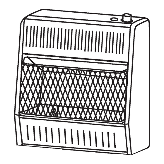
Vent-Free Gas Wall Heater
Model # 1096513.9
WS-MD100TBA-1206
Blue Flame
2096513.9
3096513.9
Advertisement
Table of Contents

Related Manuals for Williams 1096513.9


Summary of Contents for Williams 1096513.9
- Page 1 Vent-Free Gas Wall Heater Blue Flame Model # 1096513.9 2096513.9 WARNING: This appliance is equipped for (Natural and Propane) 3096513.9 gas. Field conversion is not permitted other than between natural or propane gases. HEATER IS PRESET FOR PROPANE AT FACTORY SEE INSTALLATION...
-
Page 2: Table Of Contents
IMPORTANT: Read this owner’s manual carefully and completely before trying to assemble, operate, or service this heater. Improper use of this heater can cause serious injury or death from burns, fire, explosion, and carbon monoxide poisoning. PRODUCT SPECIFICATIONS MODEL 1096513.9 2096513.9 3096513.9 BTU (available) 10,000... -
Page 3: Important Safety Information
IMPORTANT SAFETY INFORMATION IMPORTANT SAFETY INFORMATION IMPORTANT: Read this owner’s manual carefully and completely before trying to assemble, operate, or service this heater. Improper use of this heater can cause serious injury or death from burns, fire, explosion, electrical shock, and carbon monoxide poisoning. -
Page 4: Qualified Installing Agency
5. If heater shuts off, do not relight until you have provided fresh, outside air. If heater keeps shutting off, have it serviced. Do not run heater: • Where flammable liquids or vapors are used or stored. • Under dusty conditions. 7. -
Page 5: Product Features
PRODUCT FEATURES SAFETY PILOT This heater has a pilot with an Oxygen Depletion Sensing (ODS) safety shutoff system. The ODS/pilot shuts off the heater if there is not enough fresh air. PIEZO IGNITION SYSTEM This heater is equipped with an electronic piezo control system. This system requires AAA batteries (provided). TWO GAS OPTIONS CAPABLE Your heater is equipped to operate on either Propane or Natural gas. -
Page 6: Preparing For Installation
PREPARING FOR INSTALLATION Before beginning assembly or operation of the product, make sure all parts are present. Compare parts with package contents list and diagram above. If any part is missing or damaged, do not attempt to assemble, install or operate the product. -
Page 7: Air For Combustion And Ventilation
AIR FOR COMBUSTION AND VENTILATION WARNING: If the area in which the heater may be operated does not meet the required volume for indoor combustion air, combustion and ventilation air shall be provided by one of the methods described in the National Fuel Gas Code, ANSI Z223.1/NFPA 54, the International Fuel Gas Code, or applicable local codes. - Page 8 DETERMINING FRESH-AIR FLOW FOR HEATER LOCATION Determining if You Have a Confined or Unconfined Space Use this worksheet to determine if you have a confined or unconfined space. Space: Includes the room in which you will install heater plus any adjoining rooms with doorless passageways or ventilation grills between the rooms.
- Page 9 WARNING: If the area in which the heater may be operated does not meet the required volume for indoor combustion air, combustion and ventilation air shall be provided by one of the methods described in the NATIONAL FUEL GAS CODE, ANSI Z223.1/ NFPA 54, the INTERNATIONAL FUEL GAS CODE, or applicable local codes.
-
Page 10: Installation
INSTALLATION NOTICE: This heater is intended for use as supplemental heat. Use this heater along with your primary heating system. Do not install this heater as your primary heat source. If you have a central heating system, you may run system’s circulating blower while using heater. This will help circulate the heat throughout the house. In the event of a power outage, you can use this heater as your primary heat source. - Page 11 Attaching to Wall Stud Method For attaching mounting bracket to wall studs: Drill holes at marked locations using 9/64-inch drill bit. Model: 1096513.9 Place mounting bracket onto wall. Line up last hole on each end of bracket with holes drilled in wall.
- Page 12 Attaching to Wall Anchor Method For attaching mounting bracket to hollow walls (wall areas between studs) or solid walls (concrete or masonry): Drill holes at marked locations using 5/16-inch drill bit. For solid walls (concrete or masonry), drill at least 1 inch deep. Fold wall anchor as shown in Figure 8.
-
Page 13: Connecting To Gas Supply
CONNECTING TO GAS SUPPLY WARNING: A qualified service technician must connect heater to gas supply. Follow all local codes. WARNING: This appliance requires a 3/8-inch NPT (National Pipe Thread) inlet connection to the pressure regulator. WARNING: Never connect heater to private (non-utility) gas wells. This gas is commonly known as wellhead gas. WARNING: Do not over-tighten gas connections. - Page 14 Apply pipe joint sealant lightly to male threads. This will prevent excess sealant from going into pipe. Excess sealant in pipe could result in clogged heater valves. The installer must supply an external regulator. The external regulator will reduce incoming gas pressure. You must reduce incoming gas pressure to between 11 and 14 inches of water.
-
Page 15: Checking Gas Connections
Figure 14 Figure 15 Figure 16 CHECKING GAS CONNECTIONS WARNING: Test all gas piping and connections for leaks after installing or servicing. Correct all leaks at once. WARNING: Never use an open flame to check for a leak. Apply a mixture of liquid soap and water to all joints. If bubbles form, there is a leak. -
Page 16: Operation
Pressure Testing Heater Gas Connections Open equipment shutoff valve (see Figure 17). Open gas supply tank valve. Make sure control knob of heater is in the OFF position. Remove front panel. Check all joints from equipment shutoff valve to control valve (see Figure 17). Apply mixture of liquid soap and water to gas joints. -
Page 17: Lighting Instructions
LIGHTING INSTRUCTIONS STOP! Read the safety information on the side of the heater. Make sure equipment shutoff valve is fully open. Turn control knob clockwise to the OFF position. Wait five (5) minutes to clear out any gas. Then smell for gas, including near the floor. If you smell gas, STOP! Do not try to light any appliance. -
Page 18: Inspecting Burner
INSPECTING BURNER Check pilot flame pattern and burner flame pattern often. PILOT FLAME PATTERN Figure 20 shows a correct pilot flame pattern. Figure 21 shows a incorrect pilot flame pattern. The incorrect pilot flame is not touching the thermocouple. This will cause the thermocouple to cool, which shuts the heater off. If pilot flame pattern is incorrect: •... -
Page 19: Care And Maintenance
CARE AND MAINTENANCE WARNING: Turn off heater and let cool before servicing or cleaning. CAUTION: You must keep control areas, burner, and circulating air passageways of heater clean. Inspect these areas of heater before each use. Have heater inspected yearly by a qualified service technician. Heater may need more frequent cleaning due to excessive lint from carpeting, bedding material, pet hair, etc. -
Page 20: Troubleshooting
TROUBLESHOOTING WARNING: If you smell gas: • Shut off gas supply. • Do not try to light any appliance. • Do not touch any electrical switch; do not use any phone in your building. • Immediately call your gas supplier from a neighbor’s phone. Follow the gas supplier’s instructions. •... - Page 21 Problem Possible Cause Corrective Action ODS/pilot lights but flame goes out 1. Control knob is not fully 1. Press in control knob when control knob is released. pressed in. fully. 2. Control knob is not pressed 2. After ODS/pilot lights, in long enough.
- Page 22 Problem Possible Cause Corrective Action Slight smoke or odor during initial 1. Residues from 1. Problem will stop after a few operation manufacturing process. hours of operation. Heater produces a whistling noise 1. Turning control knob to 1. Turn control knob to low (1) when burner is lit.
-
Page 23: Replacement Parts
The replacement part number ACCESSORIES Purchase these heater accessories from your local dealer. figure 1 If they can not supply these accessories, contact Williams Furnace for information. EQUIPMENT SHUTOFF VALVE For all models. Equipment shutoff valve with 1/8 in. NPT tap. - Page 24 PARTS LIST (1096513.9) This list contains replaceable parts for your heater. When ordering replacement parts, follow the instructions listed under Replacement Parts on page 24 of this manual. PART PART # DESCRIPTION MB10053D Cabinet Assembly MB11005 Reflector Unite ML087-03 Upper Glass Retainer...
- Page 25 ILLUSTRATED PARTS 1096513.9...
- Page 26 PARTS LIST (2096513.9 & 3096513.9) This list contains replaceable parts for your heater. When ordering replacement parts, follow the instructions listed under Replacement Parts on page 24 of this manual. 2096513.9 3096513.9 PART DESCRIPTION PART # PART # MB10052D MB10054D Cabinet Assembly MB11004 MB11052...
- Page 27 ILLUSTRATED PARTS 2096513.9 & 3096513.9...
-
Page 28: Warranty Information
LIMITED WARRANTY: Williams Furnace Co. warrants this product to be free from defects in materials and components for ONE (1) year from the date of first purchase, provided that the product has been properly installed, operated and maintained in accordance with all applicable instructions, to make a claim under this warranty, the Bill of Sale or cancelled check must be pre- sented.
Need help?
Do you have a question about the 1096513.9 and is the answer not in the manual?
Questions and answers