Table of Contents
Advertisement
Owner's Manual
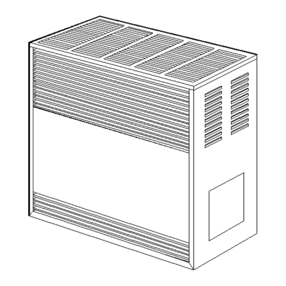
ENCLOSED MODEL
FIREPLACE MODEL
WARNING: Improper installation, adjustment, alteration,
service or maintenance can cause injury or property
damage. Refer to this manual. For assistance or for
additional information consult a qualified installer,
service agency or the gas supplier.
WARNING: Installation and repair must be done by a qualified service person. The appliance should be inspected
before use and at least annually by a professional service person.
Williams Furnace Co. 250 West Laurel Street Colton, California 92324 U.S.A.
S
Vented Room Heaters
Model Numbers:
2001622A; 2011622A; 2031622A; 2051622A; 3501522A; 3511522A;
3531522A; 3551522A; 3501922A; 3511922A; 3531922A; 3551922A;
3502522A; 3511522A; 3532522A; 3552522A; 3502922A; 3512922A;
3532922A; 3552922A; 5001522A; 5011522A; 5031522A; 5051522A;
5001922A; 5011922A; 5031922A; 5051922A; 5002522A; 5012522A;
5032522A; 5052522A; 5002922A; 5012922A; 5032922A; 5052922A;
6501522A; 6511522A; 6531522A; 6551522A; 6501922A; 6511922A;
6531922A; 6551922A; 6502522A; 6512522A; 6532522A; 6552522A;
6502922A; 6512922A; 6532922A; 6552922A
FOR USE WITH NATURAL GAS ONLY
Model Numbers:
2001621A; 2011621A; 2031621A; 2051621A; 3501521A; 3511521A;
3531521A; 3551521A; 3501921A; 3511921A; 3531921A; 3551921A;
3502521A; 3512521A; 3532521A; 3552521A; 3502921A; 3512921A;
3532921A; 3552921A; 5001521A; 5011521A; 5031521A; 5051521A;
5001921A; 5011921A; 5031921A; 5051921A; 5002521A; 5012521A;
5032521A; 5052521A; 5002921A; 5011921A; 5032921A; 5052921A;
6501521A; 6511521A; 6531521A; 6551521A; 6501921A; 6511921A;
6531921A; 6551921A; 6502521A; 6512521A; 6532521A; 6552521A;
6502921A; 6512921A; 6532921A; 6552921A
FOR USE WITH LIQUEFIED PETROLEUM (L.P.) GAS ONLY
READ THIS OWNER'S MANUAL CAREFULLY BEFORE YOU INSTALL
YOUR NEW WILLIAMS HEATER.
WARNING: If the information in these instructions
is not followed exactly, a fire or explosion may
result causing property damage, personal injury or
loss of life.
Do not store or use gasoline or other flammable
vapors and liquids in the vicinity of this or any other
appliance.
WHAT TO DO IF YOU SMELL GAS:
•
Open all windows.
•
Do not try to light any appliance.
•
Do not touch any electrical switch; do not
use any phone or cell phone in your building.
•
Extinguish any open flame.
•
Immediately call your gas supplier from a
neighbor's phone. Follow the gas supplier's
instructions.
•
If you cannot reach the gas supplier, call the fire
department.
Installation and service must be performed by a
qualified installer, service agency or the gas
supplier.
ave this manual for future reference.
Advertisement
Table of Contents

Subscribe to Our Youtube Channel
Related Manuals for Williams 2001622A


Summary of Contents for Williams 2001622A
- Page 1 WARNING: Installation and repair must be done by a qualified service person. The appliance should be inspected before use and at least annually by a professional service person. Williams Furnace Co. 250 West Laurel Street Colton, California 92324 U.S.A.
-
Page 2: Your Williams Warranty
Warranty & Installation Record – 2 Warranty The manufacturer, Williams Furnace Co., warrants this wall furnace or heater to the original purchaser under the following conditions: LIMITED ONE-YEAR WARRANTY 1. Any part thereof which proves to be defective in material or workmanship within one year from date of original purchase for use will be replaced at the Manufacturer’s option, FOB to its factory. -
Page 3: Table Of Contents
Installation Record ................. 2 Table of Contents ................3 Unpack the heater................. 5 Safety Rules .................. 4 Learn how to unpack the new Williams Heater and verify that all its parts are in working order. Introduction ..................5 Basic Description ................5 Install the heater .............. -
Page 4: Safety Rules
Safety Rules Install the heater vent directly to the outdoors, so that harmful gases will not collect inside the building. Follow WARNING: Read these rules and the instructions the venting instructions for your type of installation carefully. Failure to follow these rules and exactly. -
Page 5: Introduction
Available in black to match the heater. may use Blower Accessory Kit 2102, on all models except Vent Collar Model 9102, 9104 or 9106 2001622A and 2001621A. Available in black to match the heater. Unpack Your Heater convert unit from natural gas to L.P. Gas or from L.P. Gas to Examine all packing material carefully. -
Page 6: Installing Your Heater
Minimum fresh air Optional floor boards are available from Williams. opening of 1 square inch per 1,000 Btu/hr. input Do not place the heater where curtains, draperies, or any rating must be provided for ventilation. - Page 7 Installing Your Heater WARNING: When connecting field piping, use a FIGURE 1 Minimum Required Clearances second wrench to keep the heater valve from turning. Support field piping properly, stress and over tightening could damage the gas valve and result in dangerous gas leaks which can cause dangerous conditions including property damage, bodily injury, and even death.
-
Page 8: Combustion & Ventilation Air
Installing Your Heater FIGURE 3 Proper Piping Practice IMPORTANT: All piping must comply with local codes and ordinances or with the National Fuel Gas Code (ANSI Z223.1 NFPA No. 54), whichever applies. (In Canada: CAN/CGA B149). FIGURE 4 Enclosed Model FIGURE 5 Gas Pipe Sizes PIPE CAPACITY - Btu/hr. - Page 9 Installing Your Heater AIR REQUIREMENTS FIGURE 6 Draft Hood Spillage The requirements for providing air for combustion and ventilation are listed in the National Fuel Gas Code NFPA 54/ANSI Z223.1 (in Canada: CAN/CGA B149). Most homes will require that outside air be supplied to the heated area by means of ventilation grilles or ducts connecting directly to the outside or spaces open to the outdoors such as attic or crawl space.
- Page 10 Installing Your Heater within 12 inches of the bottom of the room connecting directly to 4. Spillage means air starvation and a fresh air duct or air unconfined space. Each opening must have a free area of at least intakes must be installed to provide air directly to the 100 square inches or 1 square inch per 1000 Btu/hr.
-
Page 11: Thermostat Installation
40 square inches. Btu/hr. Thermostat Installation Williams’ heaters are operated by a millivolt type thermostat. and push a small stiff wire through the hole so it can be found Current to the thermostat is supplied by the pilot generator. Do not in the attic. - Page 12 Installing Your Heater 7. Connect the thermostat wires to the control valve as shown in CAUTION: Label all wires prior to disconnection Figure 5. when servicing controls. Wiring errors can cause improper and dangerous operation. Verify proper operation after servicing. IMPORTANT: KEEP THE THERMOSTAT WIRE AWAY FROM THE COMBUSTION CHAMBER.
-
Page 13: Vent Installation
Installing Your Heater Vent Installation 3. Use vent pipe of the same size as the outlet on back of heater. This heater must be properly connected to a venting system. This In no case should a different size vent be used. Single wall heater is equipped with a vent safety shutoff system to protect vent pipe may be attached directly to the draft hood of the against improper venting of combustion products. - Page 14 Installing Your Heater IMPORTANT: Inspect venting system prior to each heating season. FIGURE 14 Venting Into A Masonry Typical Methods of Safely Venting Your Heater Chimney 1. Any horizontal run of vent pipe must slope upward a minimum of 1/4” per foot. Secure all joints of the vent with sheet metal screws.
-
Page 15: Installing Your Heater
Installing Your Heater FIGURE 16 Venting Into An Outside Type FIGURE 15 Straight Up Venting With Type “B” Gas Vent “B” Gas Vent See Figure 1 “C” 3 in. (7 cm) -
Page 16: Operating Your Heater
Operating Your Heater Start-Up Procedure Start the heater using the procedures in the section “Operating CHECK THE GAS INPUT (NATURAL GAS ONLY) Your Heater”. WARNING: Natural gas heating value (Btu per WARNING: Danger of bodily injury or death. L.P. cubic foot) can vary significantly. Therefore, it is Gas is heavier than air and it will settle in any low the installer's responsibility to see that Btu/hr. - Page 17 Operating Your Heater Abnormal Appearance FIGURE 18 Burner Flame Characteristics Lazy Flame: Long soft yellow cones moving around in the combustion chamber lifting from ports (insufficient air). Extremely Fast Flame: Will not hold to ports - entire cone sections blow off from noisy ports (too much pressure).
-
Page 18: Operating Instructions
Operating Your Heater FOR YOUR SAFETY, READ BEFORE LIGHTING • If you cannot reach your gas supplier, call the fire department. WARNING: If you do not follow these instructions Use only your hand to push in or turn the gas control knob. exactly, a fire or explosion may result causing Never use tools. -
Page 19: How To Care For Your Heater
Care – 19 Caring for Your Heater How To Care For Your Heater For better circulation and more effective heating, do not place WARNING: Danger of bodily injury or death. Turn obstructions, furniture or other items closer than four feet to the off electric power supply at the disconnect switch, front of the cabinet or two feet from each side of the cabinet. - Page 20 Caring for Your Heater CLEANING BURNER COMPARTMENT FIGURE 21 Log Mounting Because cold air is attracted to the flame during heater operation, a build up of lint from carpeting, bedding, dust, etc. in the burner area will occur. It is necessary to clean this area regularly. Use a vacuum cleaner with a narrow attachment to reach small areas.
-
Page 21: Repair Parts & Parts Lists
Accessories– 21 Replacement Parts FOR MODELS: 2001621A; 2011621A; 2031621A; 2051621A; 2001622A; 2011622A; 2031622A; 2051622A FOR PART LIST SEE PAGE 22. - Page 22 Replacements Parts REPLACEMENT PARTS LIST FOR MODELS 2001621A; 2011621A; 2031621A; 2051621A; 2001622A; 2011622A; 2031622A; 2051622A PART NO. FOR MODEL Ref. Description 2001621A; 2011621A; 2001622A; 2011622A; Number 2031621A; 2051621A 2031622A; 2051622A Wrapper Assembly K000275 K000275 Draft Diverter Assembly K000274 K000274 Combustion Chamber...
- Page 23 Accessories– 23 Replacement Parts ENCLOSED FRONT FOR PART LIST SEE PAGE 24.
- Page 24 Replacements Parts REPLACEMENT PARTS LIST FOR ENCLOSED FRONT PART NO. FOR MODEL 3501522A 3501521A 5001522A 5001521A 6501522A 6501521A 3511522A 3511521A 5011522A 5011521A 6511522A 6511521A 3531522A 3531521A 5031522A 5031521A 6531522A 6531521A Ref. Description 3551522A 3551521A 5051522A 5051521A 6551522A 6551521A Number 3501922A 3501921A 5001922A 5001921A...
- Page 25 Accessories– 25 Replacement Parts FIREPLACE-LOOK WITH LOGS FOR PART LIST SEE PAGE 26.
- Page 26 Replacements Parts REPLACEMENT PARTS LIST FOR FIREPLACE-LOOK WITH LOGS PART NO. FOR MODEL 6502522A 6502521A 3502522A 3502521A 5002522A 5002521A 6512522A 6512521A 3512522A 3512521A 5012522A 5012521A 6532522A 6532521A 3532522A 3532521A 5032522A 5032521A Ref. 6552522A 6552521A 3552522A 3552521A 5052522A 5052521A Description Number 6502922A 6502921A 3502922A...
-
Page 27: Blower Accessory 2102
Accessories– 27 Blower Accessory 2102 Mounting the Blower Note: All electrical work must conform to your local codes and ordinances or in their absence, with National Electrical Code, ANSI/NFPA 70. If you are not familiar with wiring codes in general, have a competent electrician do this job. In CANADA: CANADIAN ELECTRICAL CODE C22.1. - Page 28 Blower Accessory 2102 Operation This accessory is operated using the factory equipped, three-prong (grounding) plug and cord. When using the plug and cord, for your protection against shock hazard, it must be plugged directly into a properly grounded three-prong receptacle. DO NOT CUT OR REMOVE THE PRONG.
-
Page 29: Troubleshooting Chart
Troubleshooting SYMPTOM POSSIBLE CAUSE CORRECTIVE ACTION A. Generator producing Check pilot flame – it must impinge on the generator from 1/4 to 3/8-inches . insufficient millivolts. Be sure the thermocouple is fully inserted in its bracket. B. Loose or dirty generator Clean and/or tighten the connections at the valve. - Page 30 Troubleshooting SYMPTOM POSSIBLE CAUSE CORRECTIVE ACTION A. Thermostat wiring Thermostat lead wires may be shorted together, caused by a nail or staple. defective. Check by removing thermostat leads from valve terminals. 5. Heater operates, Check thermostat location. If on an outside wall, or there is a hole in the wall but will not shut off B.
- Page 31 Troubleshooting A. Delayed ignition - pilot Adjust pilot flame. Refer to "How to Care for Your Heater" section in this flame may be too low. manual. Heater may be distorted by being vented through an uneven opening. A B. Expansion noise, restricted vent may create expansion noise.
-
Page 32: Service Hints
3. PART NUMBER 4. PART DESCRIPTION All parts listed herein may be ordered from your equipment supplier. The Model Number of your Williams heater will be found on the nameplate near the gas valve, inside the control compartment. Williams Furnace Company • 250 West Laurel Street, Colton, CA 92324 (909) 825-0993 •...
Need help?
Do you have a question about the 2001622A and is the answer not in the manual?
Questions and answers