Table of Contents
Advertisement
OWNER'S MANUAL
INSTALLATION INSTRUCTIONS
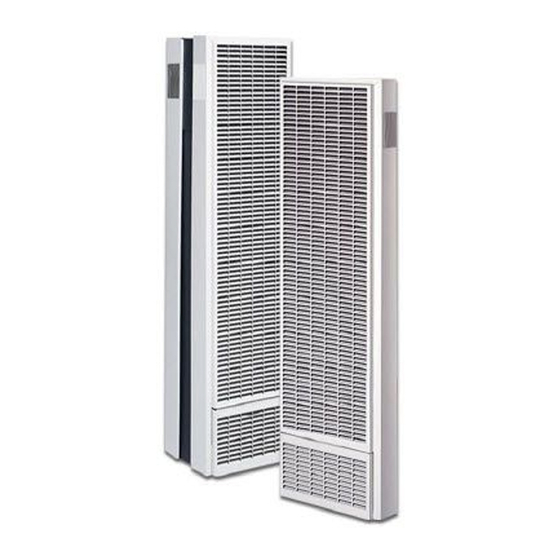
MONTEREY PLUS + HOME FURNACE
TOP VENT GAS WALL HEATER
SINGLE SIDED MODEL NUMBERS
(natural gas)
2509822A / 3509822A
(propane gas)
2509821A / 3509821A
DOUBLE SIDED MODEL NUMBERS:
(natural gas)
5009822A
(propane gas)
5009821A
DISCONTINUED MODEL NUMBERS:
2519822 / 2559822 / 3519822 / 3539822 / 3559822 /
5019822 / 6039822 / 5059822 / 3519821 / 3559821 /
3519821 / 3539821 / 3559821 / 5019821 / 5039821 / 5059821
SAVE THIS MANUAL FOR FUTURE REFERENCE.
READ THIS OWNER'S MANUAL CAREFULLY BEFORE YOU
INSTALL YOUR NEW WILLIAMS WALL FURNACE.
WARNING: Do not install any of these furnaces
(natural or propane gas) in mobile/manufactured homes,
trucks or recreational vehicles.
WARNING: This product can expose you to
chemicals including epichlorohydrin which is known to
the State of California to cause cancer and birth defects
and/or other reproductive harm. For information go to
www.p65warnings.ca.gov
WARNING: Improper installation, adjustment,
alteration, service or maintenance can cause injury or
property damage. Refer to this manual. For assistance or
for additional information consult a qualified installer,
service agency or the gas supplier.
250 West Laurel Street, Colton CA 92324 • WWW.WFC-FC.COM • 1-888-444-1212
TM
25,000 - 35,000
BTU/hr.
WARNING: If the information in these instructions
is not followed exactly, a fire or explosion may result
causing property damage, personal injury or loss of life.
- Do not store or use gasoline or other flammable vapors
and liquids in the vicinity of this or any other appliance.
WHAT TO DO IF YOU SMELL GAS:
• Open all windows.
• Do not try to light any appliance.
• Do not touch any electrical switch; do not use
any phone or cell phone in your building.
• Extinguish any open flame.
• Immediately call your gas supplier from a neighbor's
phone. Follow the gas supplier's instructions.
• If you cannot reach the gas supplier, call the fire
department.
– Installation and service must be performed by a
qualified installer, service agency or the gas supplier.
50,000 BTU/hr.
Advertisement
Table of Contents

Subscribe to Our Youtube Channel
Related Manuals for Williams 2509822A


Summary of Contents for Williams 2509822A
- Page 1 BTU/hr. READ THIS OWNER’S MANUAL CAREFULLY BEFORE YOU WARNING: If the information in these instructions INSTALL YOUR NEW WILLIAMS WALL FURNACE. is not followed exactly, a fire or explosion may result causing property damage, personal injury or loss of life.
-
Page 2: Your Williams Warranty
WARRANTY The manufacturer, Williams Furnace Co., warrants this wall furnace This warranty does not include any charge for labor or or heater to the original purchaser under the following conditions: installation. LIMITED ONE-YEAR WARRANTY This warranty does not extend to painted surfaces or to damage... -
Page 3: Table Of Contents
CONTENTS Quick Reference YOUR WILLIAMS WARRANTY Here’s how to: INSTALLATION RECORD INSTALLING YOUR FURNACE TABLE OF CONTENTS Recessed Mount, Surface Mount, and Vent Installation are SAFETY RULES explained starting on page 11. INTRODUCTION OPERATING YOUR FURNACE BASIC MATERIALS NEEDED Igniting your furnace for the first time. -
Page 4: Safety Rules
SAFETY RULES Provide for adequate combustion and ventilation air. See WARNING: Read these rules and the instructions page 7. The flow of this air to the furnace must not be blocked. carefully. Failure to follow these rules and instructions could cause a malfunction of the furnace. This could 10. -
Page 5: Introduction
INTRODUCTION The following steps are all needed for proper installation to propane gas or from propane gas to natural gas without and safe operation of your furnace. If you have any doubts the proper manufacturer’s gas conversion kit. as to any requirements, check with local authorities. Obtain Combustion air is drawn in from the room where the professional help where needed. -
Page 6: Basic Materials Needed
INTRODUCTION Basic Materials Needed Optional Accessories Pipe and fittings to make gas connections to the furnace. Blower Accessories 2901, 2907 - May be used on all models and mounts on top of a furnace. This blower increases Vertical venting materials. See page 15, Figure 8. ... -
Page 7: Installing Your Wall Furnace
INSTALLING YOUR FURNACE The following steps are needed for proper installation and Locate the furnace near the center of the space to be safe operation of your furnace. If you have any doubts as to heated for good air circulation. Do not put it behind a door or draperies. -
Page 8: Combustion & Ventilation Air
INSTALLING YOUR FURNACE After picking a location that meets the requirements, check After it has been determined that each appliance the walls, attic and roof to make sure there are no obstructions connected to the venting system properly vents when such as pipes, electrical wiring, etc., which could interfere with tested as outlined above, return doors, windows, exhaust the installation of the furnace or vent pipe. - Page 9 If the furnace is installed in an area with another gas A. No Spillage appliance(s), the total input rating of all appliances must be If the match flame pulls toward draft hood, this indicates considered when determining the free area requirements sufficient infiltration air.
- Page 10 INSTALLING YOUR FURNACE HOLE PLACEMENT - EXAMPLE EXAMPLES OF GRILL PLACEMENT HOLES FROM VENTILATED VENTILATION GRILLES CONNECTING TWO ATTIC INTO STUD SPACE ROOMS TO MEET UNCONFINED SPACE 100 SQ IN VENTILATION 200 SQ IN MINIMUM GRILLES BETWEEN INTO CLOSET LARGE FOR HOT ROOMS WATER...
-
Page 11: Recessed Mount Installation
furnace is recessed into the wall. In new construction, install WARNING: Danger of illness, bodily injury or death. the rear outlet plaster ground at the same time you install the Draft hood spillage, with unobstructed vents, indicates header plate. For existing construction, make the necessary that additional air must be brought into the structure cutout and install the plaster ground before you install the from the outside. - Page 12 INSTALLING YOUR FURNACE CLOSE OFF STUD SPACE (IF REQUIRED) INSTALL CEILING PLATE SPACER Nail the ceiling plate spacers either across or in between If studs are not on 16-inch centers, cut the hole for the the cut out section of ceiling plate. If nailed between, ends furnace next to an existing stud and frame in the other side using a 2 x 4 and spacer blocks as required.
-
Page 13: Surface Mount Installation
Surface Mount Installation Installation, page 15. The use of the optional Free Standing Accessory No. Set the furnace body into position. (Figure 9), page 15. 4901 allows single-sided furnaces to be surface mounted The furnace legs will rest on the bottom of the base instead of recessed into a wall. - Page 14 INSTALLING YOUR FURNACE FIGURE B FIGURE C STUD WALL STUD WALL 3 - 1/2ʺ 4 - 7/16ʺ CENTERED 14ʺ 16ʺ FIGURE D CEILING PLATE SPACER STUD WALL STUD WALL GAS STUB LOCATIONS PLUMBERS TAPE VENT INSTALLED B-W VENT PIPING FRONT PANEL INSTALLED VENT HOLD DOWN PLATE...
-
Page 15: Vent Installation
Vent Installation FIGURE 8 – TYPICAL VENT INSTALLATION The vent installation must comply with all local codes and ordinances. If in doubt, consult your local codes or inspector. VENT CAP MUST BE MINIMUM 2 FEET The furnace vent must be directed to the outdoors so that HIGHER THAN ANY POINT WITHIN harmful combustion gases will not collect inside the building. -
Page 16: Attaching Your Furnace
If an existing gas line is preventing the installation of a Swing the plate outward; bend it back and forth to Williams Monterey unit, a cut-out may be made using tin break the top tabs. Use caution when handling sharp snips on one of the legs to clear this existing gas line. -
Page 17: Gas Supply And Piping
Gas Supply and Piping NATURAL GAS TO PROPANE GAS 8907 25098 SERIES WITH WILLIAMS BRAND GAS VALVE The gas control valve, in the furnace, is shipped with a seal over the gas inlet tapping. Do not remove the seal until ready... - Page 18 INSTALLING YOUR FURNACE FIGURE 14 – GAS PIPING GAS PIPING MANUAL SHUT-OFF VALVE The gas supply line must be of adequate size to handle the DROP Btu/hr. requirements and length of the run for the unit being installed. GROUND JOINT UNION HORIZONTAL Determine the minimum pipe size from Figure 13, based on 1/8ʺ...
-
Page 19: Front Panel Installation
FIGURE 16 – PANEL PLACEMENT valve to prevent turning and/or damage to the valve. Connections between the manual shutoff valve and burner control assembly can be made with an A.G.A./C.G.A. design certified flexible connector if allowed by local codes. Drip leg and ground joint unions are still required. -
Page 20: Thermostat Installation
20-feet. If a longer length is needed, use 16-gauge wire to a maximum length of 25-feet. Use Williams thermostat P322016 or any millivolt 8. Connect the thermostat wires to the control valve as thermostat. Current to the thermostat is supplied by the shown in Figure 17. -
Page 21: Start Up Procedure
Start-Up Procedure CHECK THE MANIFOLD GAS PRESSURE A tapped opening is provided in the gas valve to facilitate WARNING: Danger of property damage, bodily measuring manifold gas pressure. A water column injury or loss of life. propane gas is heavier than air and manometer having a scale range from 0 to 12-inches of may settle in any low area, including open depressions water column should be used for this measurement. -
Page 22: Stay Safe
OPERATING YOUR FURNACE Start-Up Procedure (continued) PROPANE GAS: 1. Inner cone-blue in color-1/2 to 3/4-inches above ports. CHECK PILOT BURNER 2. Secondary inner cone-light blue in color-1 to 2-inches The pilot flame must surround the generator tip from 1/4 to above ports. -
Page 23: Operating Your Furnace
WHAT TO DO IF YOU SMELL GAS 5. Push in gas control knob slightly and turn clockwise to “OFF”. (Figure 21) • Do not try to light any appliance or strike a match. • Do not touch any electrical switch; do not use any FIGURE 21 - GAS CONTROL KNOB phone or cell phone in your building. - Page 24 OPERATING YOUR FURNACE For your safety, read before lighting the pilot (continued) WARNING: The surface of the furnace is hot during operation. Keep children, clothing, furniture, and flammable material away from it. Keep all access 1. Set the thermostat to lowest setting. doors and panels in place except for inspection and 2.
-
Page 25: How To Care For Your Furnace
CARING FOR YOUR FURNACE CLEANING BLOWER (IF APPLICABLE) FIGURE 24 DISCONNECTING GAS LINE Shut off electricity. Clean any lint or dirt from fan blades, fan motor and exposed air passages. PILOT BURNER Using the instructions in “Lighting the Pilot”, leave thermostat at its lowest setting.Pilot flame should surround the generator tip 1/4 to 3/8-inches. -
Page 26: Installing Your Blower Accessory
INSTALLING YOUR BLOWER ACCESSORY BLOWER ACCESSORY 2901 AND 2907 FIGURE A INSTALL ELECTRICAL OUTLET This blower accessory is installed on the furnace top and increases circulation of warm air through the heated space. A 115V electrical outlet adjacent to the furnace is required. For automatic setting, you must select the “HI”... - Page 27 FIGURE C WIRING FOR MODEL 2901 FIGURE D WIRING FOR MODEL 2907 MONTEREY PLUS TOP VENT GAS WALL HEATER...
-
Page 28: Installing Your Motorized Rear Outlet
INSTALLING YOUR MOTORIZED REAR OUTLET ACCESSORY MOTORIZED REAR OUTLET REGISTER 6919 AND 6920 be removed in order to attach the register assembly properly. If the inner shield knockout is not embossed deep enough to be removed easily, mark an outline WARNING: Danger of property damage, bodily using the existing opening as a guide. - Page 29 FIGURE C - SURFACED MOUNTED INSTALLATION FIGURE D - SURFACED MOUNTED INSTALLATION FIGURE E - SURFACE MOUNTED INSTALLATION FIGURE F - WIRING MONTEREY PLUS TOP VENT GAS WALL HEATER...
-
Page 30: Part Numbers For The 250 / 350 Models
PART NUMBERS FOR THE 250 / 350 MODELS SINGLE SIDED 1 IN. SIDE CLEARANCE NATURAL 2509822 3509822 PROPANE 2508921 3509821 REF. REPLACEMENT PART DESCRIPTION 2509822 3509822 2508921 3509821 Face Panel 4915 4915 4915 4915 Front Heat Shield 9C216 9C216 9C216 9C216 Combustion Chamber 6922... - Page 31 EXPLODED VIEW & REPLACEMENT PARTS CHART MONTEREY PLUS TOP VENT GAS WALL HEATER...
-
Page 32: Control Assembly Replacement Parts
CONTROL ASSEMBLY REPLACEMENT PARTS 250 / 350 MODELS MODEL NUMBERS 2509822 3509822 2509821 3509821 REF. REPLACEMENT PART DESCRIPTION 2509822 3509822 2509821 3509821 Wire Assembly (Both Required) P321836/A P321836/A P321836/A P321836/A Valve P323011 P323011 P322660 P322660 Front Burner Bracket 9B234 9B234 9B234 9B234 Manifold... - Page 33 MONTEREY PLUS TOP VENT GAS WALL HEATER...
-
Page 34: Part Numbers For The 500 Models
PART NUMBERS FOR THE 500 MODELS DOUBLE SIDED SIDED 4 IN. SIDE CLEARANCE NATURAL 5009822 PROPANE 5009821 REF. REPLACEMENT PART DESCRIPTION 5009822 5009821 Face Panel (2 Required) 4915 4915 Front Heat Shield (2 Required) 9C216 9C216 Carryover Shell 9A321-1 9A321-1 Combustion Chamber (2 Required) 9D97/9D98 9D97/9D98... - Page 35 EXPLODED VIEW & REPLACEMENT PARTS CHART MONTEREY PLUS TOP VENT GAS WALL HEATER...
-
Page 36: Control Assembly Replacement Parts 500 Models
CONTROL ASSEMBLY REPLACEMENT PARTS 500 MODELS MODEL NUMBERS 5009821 5009822 REF. REPLACEMENT PART DESCRIPTION 5009821 9A409 / 5009822 Wire Assembly (Both Required) P321836/A P321836/A Valve P322660 P323011 Front Burner Bracket 9B243 9B243 Manifold P323661 P323661 Burner Orifice (2) P332623 P332625 Pilot/Generator Assembly P322397 P322396... -
Page 37: Blower Accessory Model 2901 Parts
BLOWER ACCESSORY MODEL 2901 PARTS MODEL NUMBER 2901 REF. REPLACEMENT PART DESCRIPTION PART NUMBER Screw - #8Ax 3/8 (8) P013200 Blower Grille 9C99 Screw - #8Ax 3/8 (8) P093200 Screw - #10 x ½ P141000 Toggle Switch P320911A Wire Bridle P320912 Flat Washer - #10-31 (2) P127300... -
Page 38: Blower Accessory Model 2907 Parts
BLOWER ACCESSORY MODEL 2907 PARTS MODEL NUMBER 2907 REF. REPLACEMENT PART DESCRIPTION PART NUMBER Blower Grille 9C99 Orifice Plate 9B246 Wire Assemblies P323085 / P323086 / P323377 Blower and Motor P323423 Heat Sensor Wire Assemblies P274202 / P109600 Junction Box Cover 9A483 Fan Switch P323080... -
Page 39: Motorized Rear Outlet Replacement Parts
MOTORIZED REAR OUTLET REPLACEMENT PARTS MODEL NUMBERS 6919 6920 REF. REPLACEMENT PART DESCRIPTION 6919 6920 Register Assembly 9B269 9B285 Strain Relief Bushing P500185 P500185 J-Box Cover 9A427 9A427 Strain Relief Bushing P603108 P603108 Heat Sensor Switch P323172 P323172 Fan Switch P323080 P323080 Motor and Blower... -
Page 40: Troubleshooting Your Furnace
TROUBLESHOOTING YOUR FURNACE CORRECTIVE ACTION ISSUE POSSIBLE CAUSE(S) Check pilot flame. It must impinge on the generator. Pilot will not stay lit after Generator producing following lighting instructions. insufficient millivolts. Loose or dirty generator Clean and/or tighten generator connections at valve. connections at gas valve. - Page 41 CORRECTIVE ACTION ISSUE POSSIBLE CAUSE(S) Tighten blower screws. Housing rattling. Noisy blower. Clean blower wheel. Blower dirty. Straighten or replace. Blower wheel bent. Select fan speed. Fan switch not set. Blower does not run. Blockage in vent pipe. Check vent pipe for blockage, such as bird nests, Main burner will not stay on.
-
Page 42: Hints And Information
PART NUMBER PART DESCRIPTION All parts listed herein may be ordered from your equipment supplier. The Model Number of your Williams wall furnace will be found on the nameplate near gas valve, inside control compartment. MONTEREY PLUS TOP VENT GAS WALL HEATER... -
Page 43: Installations In The State Of Massachusetts
INSTALLATIONS IN THE STATE OF MASSACHUSETTS A CARBON MONOXIDE DETECTOR SHALL: All installations in the State of Massachusetts must use a. Be located in the room that houses the appliance the following requirements when installing, maintaining or equipment; or operating direct-vent propane or natural gas-fired space heaters. - Page 44 www.williamscomfortprod.com | 888-444-1212 | 250 West Laurel Street, Colton CA 92324 USA Subject to change without notice | © 2021 P323738_RV 03/21...
Need help?
Do you have a question about the 2509822A and is the answer not in the manual?
Questions and answers