Advertisement
Table of Contents
- 1 Table of Contents
- 2 Unit Features
- 3 Installation Instructions
- 4 Wiring
- 5 Operating Instructions
- 6 Maintenance and Cleaning
- 7 Obtaining Service
- 8 Normal Operating Sounds and Conditions
- 9 Configuration Settings
- 10 Configuration Chart
- 11 Diagnostic Maintenance & Status Report
- 12 Diagnostic Codes
- Download this manual
I
NSTALLATION
Standard and Remote Applications with LED Control
ATTENTION INSTALLING PERSONNEL
As a professional installer you have an obligation to know the
product better than the customer. This includes all safety pre-
cautions and related items.
Prior to actual installation, thoroughly familiarize yourself with
this Instruction Manual. Pay special attention to all safety warn-
ings.
Often during installation or repair it is possible to place yourself
in a position which is more hazardous than when the unit is in
operation.
IO-447B
03/2017
5151 San Felipe, Suite 500
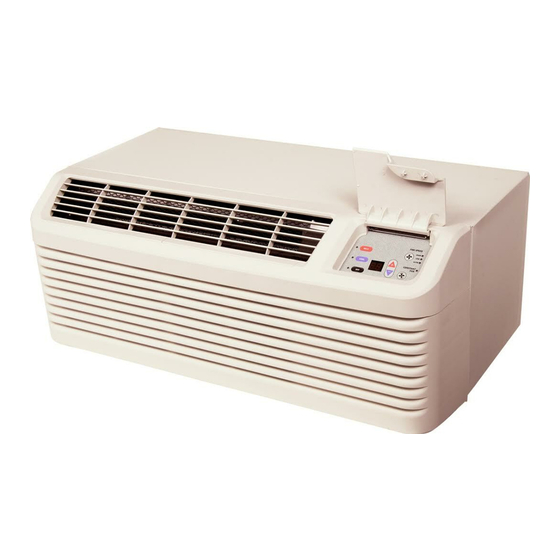
PACKAGE TERMINAL
AIR CONDITIONER/HEAT PUMP
I
NSTRUCTIONS
This manual must be left with the owner of the equipment.
is a registered trademark of Maytag Corporation or its related companies and is used
under license to Goodman Company, L.P., Houston, TX, USA. All rights reserved.
•
© 2014 - 2015, 2017 Goodman Company, L.P.
& O
Remember, it is your responsibility to install the product safely
and to know it well enough to be able to instruct a customer in
its safe use.
Safety is a matter of common sense...a matter of thinking before
acting. Most dealers have a list of specific good safety
practices...follow them.
The precautions listed in this Installation Manual are intended as
supplemental to existing practices. However, if there is a direct
conflict between existing practices and the content of this manual,
the precautions listed here take precedence.
Houston, TX 77056 •
'
M
WNER
S
ANUAL
www.amana-ptac.com
Advertisement
Table of Contents


Need help?
Do you have a question about the PTH123G25AXXX and is the answer not in the manual?
Questions and answers