Table of Contents
Advertisement
Quick Links
Advertisement
Table of Contents

Related Manuals for BK Radio GPH-CMD


Summary of Contents for BK Radio GPH-CMD
- Page 1 GPH-CMD PORTABLE RADIO Service Manual...
-
Page 2: Table Of Contents
2.2.1.4.13 REVIEW GLOBAL PARAMETERS (GRP 00)........2-13 2.2.1.5 EXIT PROGRAMMING MODE................2-13 2.2.2 CLONING RADIO SETTINGS ..................... 2-13 TONE CODE GUARD VALUES ....................2-16 DIGITAL CODE GUARD VALUES..................... 2-16 Specifications are subject to change without notice. BK RADIO Page i... - Page 3 General Information GPH-CMD VHF Radio SECTION III OPERATION INTRODUCTION .......................... 3-1 3.1.1 FEATURES ..........................3-1 FCC REQUIREMENTS ........................ 3-1 3.2.1 RF ENERGY EXPOSURE AWARENESS & CONTROL INFORMATION, AND OPERATIONAL INSTRUCTIONS FOR FCC OCCUPATIONAL USE REQUIREMENTS ..3-2 3.2.2 FEDERAL COMMUNICATIONS COMMISSION REGULATIONS ........3-2 3.2.3...
- Page 4 GPH-CMD VHF Radio General Information 3.14 ALPHANUMERIC DISPLAY....................... 3-18 3.14.1 DISPLAY BACKLIGHTING ....................3-19 3.14.2 CHANNEL AND GROUP LABELS ..................3-19 3.15 DEFINITIONS AND ACRONYMS ....................3-20 FIGURE 3-1 LIQUID CRYSTAL DISPLAY..................3-18 SECTION IV THEORY OF OPERATION INTRODUCTION .......................... 4-1 DESCRIPTION ..........................
- Page 5 General Information GPH-CMD VHF Radio SECTION VI ILLUSTRATED PARTS LIST INTRODUCTION .......................... 6-1 PARTS LIST DESCRIPTION ....................... 6-1 ASSEMBLY DRAWING SYMBOLS ..................... 6-1 FINAL ASSEMBLY ............................ 6-2 INTERCONNECT DIAGRAM ........................6-5 SYSTEM FRAME ASSEMBLY........................6-7 CONTROL BOARD (505-662) ......................6-13 SYSTEMS BOARD (309-610) ......................
-
Page 6: Section I
BK Radio GPH-CMD radios. DESCRIPTION The GPH-CMD radios are self-contained VHF FM Radios covering the frequency range of 136MHz to 174MHz. The radios are multi-channel and digitally synthesized using a single crystal for frequency control. All models incorporate an EEPROM for the storage of data such as channel frequencies, Code Guards, and channel labels. -
Page 7: Technical Characteristics
General Information GPH-CMD VHF Radio TECHNICAL CHARACTERISTICS POWER SUPPLY: One rechargeable nickel-cadmium or nickel-metal-hydride battery pack with temperature sensor or one alkaline battery pack OPERATIONAL FEATURES: Programmable Switches User Selectable Transmit Code Guard Dual Priority Scan Frequency Display Transmit Time-Out Timer... -
Page 8: Accessories
FCC, and will program each radio with your authorized frequencies and signaling codes. Service Information If you need service, contact your local BK Radio dealer equipped to service your radio. If you find it impractical to have service performed by your local dealer, contact BK Radio at the address... -
Page 9: Installation And Programming
2.1.2 BATTERY INSTALLATION A. BK Radio battery packs are available in a variety of sizes and types for special applications. Rechargeable battery packs can be charged separately or while attached to a radio. NOTE: For safety reasons, rechargeable battery packs are shipped uncharged or only partially charged. -
Page 10: How To Program Radios
GPH radio by using a cloning cable, LAA0700. See “Cloning Radio Settings" in section 2.2.2. C. BY COMPUTER With a computer, GPH-CMD programming software and an LAA0725 interface cable. That procedure is not described in this manual. Contact BK Radio for the programming cable and required software. -
Page 11: Navigation
GPH-CMD VHF Radio Installation and Programming 2.2.1.1 NAVIGATION When Programming Mode is entered, programming starts (after password entry) with the Group Parameters (CH 00) for the currently selected group. To edit another Channel Group (GRP 01 - 25), press and hold the [#] key at any CH prompt to get the group selection prompt. -
Page 12: Group Parameters (Ch 00)
If no change is needed, press the [FCN] key to go back to the starting point for Channel 0 settings. NOTE: Special software available from BK Radio lets you enter Group Labels and Channel Labels from a computer. Contact your dealer for information. -
Page 13: Channel Parameters (Ch 01 - Ch 20)
GPH-CMD VHF Radio Installation and Programming Keys 0 and 1 can be used to enter the following characters: 0, space, –, _, ., *, + 1, <, >, /, \, |, $, %, h Press the [ENT] key to store changes and go back to the starting point for Channel 0 settings. -
Page 14: Transmit Frequency
Installation and Programming GPH-CMD VHF Radio the [ENT] key to store the Code Guard value and automatically advance to the next field. 2.2.1.3.4 TRANSMIT FREQUENCY After the RX GUARD is set, the ‘TX FREQUENCY’ field appears. PROG TX This is the transmitter frequency for Channel 1. -
Page 15: Global Parameters (Grp 00)
GBL OPTIONS fast squelch attack time. NOTE: BK Radio current drain and battery life specifications are based on performance with the battery saver on. OPTION 2: RESERVED FOR FUTURE OPTIONS OPTION 3: TRANSMIT ON PRIORITY 1... - Page 16 Installation and Programming GPH-CMD VHF Radio OPTION 4: PRIORITY 1 LOCK When Option 4 is enabled (flashing) the user will not be able to PROG change the designation of the Priority 1 Channel by selecting a 1-12345678 channel and pressing the [PRI] key.
-
Page 17: Global Options Two: 2-12345678
GPH-CMD VHF Radio Installation and Programming 2.2.1.4.3 GLOBAL OPTIONS TWO: 2-12345678 After the first group of Global Options is set, a second group is PROG displayed. 2-12345678 GBL options OPTION 1: RESERVED FOR FUTURE OPTIONS OPTIONS 2 & 3: BUSY CHANNEL OPERATION... -
Page 18: Automatic Numeric Identification (Ani)
Installation and Programming GPH-CMD VHF Radio OPTIONS 6 – 8: RESERVED FOR FUTURE OPTIONS Once each option is set as desired, you can store the changes, discard the changes, or disable all displayed options. Press the [CLR] key to disable all displayed options (steady). -
Page 19: Scan Delay Time
GPH-CMD VHF Radio Installation and Programming 2.2.1.4.6 SCAN DELAY TIME After the Time-Out Timer is set, the ‘SCAN DELAY’ time is PROG displayed. 2.0 sec scan delay Press the [PRI] key to increase the scan delay time by .5 seconds, up to 7.5 seconds. Press the [PRI] key again to change the time from 7.5 seconds to 0. -
Page 20: Priority 1 Group
Installation and Programming GPH-CMD VHF Radio Press the [PRI] key to cycle through the priority channel options. Setting the channel to MAIN ties the PR1 channel to the Channel Selector knob. Press the [ENT] key to store the new priority channel and advance to the next field. -
Page 21: 2.2.1.4.12 Old-Style Bk Priority Scan
2.2.2 CLONING RADIO SETTINGS Any “Master” radio (a GPH-CMD with the desired radio frequencies and settings) is capable of transferring its program to another GPH-CMD or GPH radio. The radio receiving the program is referred to as the “Slave” or “Clone.” The LAA0700 cloning cable will be required in the following procedure. - Page 22 Installation and Programming GPH-CMD VHF Radio When receiving an incoming clone from a GPH radio, the GPH-CMD radio ignores group data other than the group label and the group scan list bit. The GPH-CMD’s global data and channels 17-20 are not disturbed.
- Page 23 GPH-CMD VHF Radio Installation and Programming 9. Once the target and data to be transferred have been selected, press the [FCN] key on the Master radio keypad. The top line of the display CLONING will flash ‘CLONING’ while the program in the master is being Group 01 downloaded to the clone.
-
Page 24: Tone Code Guard Values
(RF) channel or adjacent channels in the same coverage area should be made from one of the Groups A, B, or C to the maximum degree possible. BK Radio guarantees optimum receiver performance only if tone frequencies below 220 Hz are chosen. -
Page 25: Introduction
OPERATION INTRODUCTION This section contains information concerning the operation procedures for the BK Radio GPH- CMD radios. The GPH-CMD radio has been designed to meet the tough requirements of today’s communications environment. Please take a moment to read the information in this manual so you can get optimum performance from your new radio. -
Page 26: Operational Instructions For Fcc Occupational Use Requirements
Exposure awareness can be facilitated by the use of a product label directing users to specific user awareness information. Your BK Radio 2- way radio has a RF exposure product label. Also, your BK Radio owner’s and service manuals include information and operating instructions required to control your RF exposure and to satisfy compliance requirements. -
Page 27: Compliance With Rf Exposure Standards
3.2.3 COMPLIANCE WITH RF EXPOSURE STANDARDS Your BK Radio 2-way radio is designed and tested to comply with a number of national and international standards and guidelines (listed below) for human exposure to radio frequency electromagnetic energy. This radio complies with the IEEE and ICNIRP exposure limits for... -
Page 28: Safety Precautions
Antenna should be kept away from eyes. • When worn on the body, always place the radio in a BK Radio approved clip, holder, holster, case, or body harness for this product. Using approved body-worn accessories is important because the use of BK Radio or other manufacturer’s non-approved... -
Page 29: Radio Controls
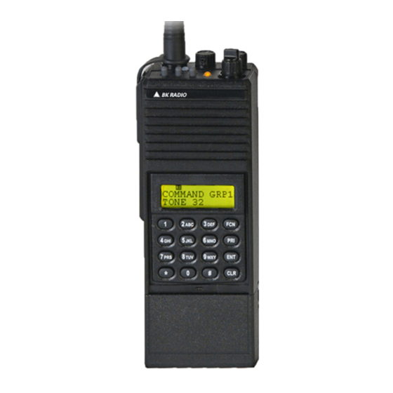
GPH-CMD VHF Radio Operation RADIO CONTROLS TRANSMIT TRANSMIT INDICATOR INDICATOR BK RADIO SQUELCH SQUELCH ANTENNA CODE GUARD ANTENNA CODE GUARD ON/OFF VOLUME OFF- 9 10 HI/LO CHANNEL HI/LO GPH-CMD RADIO TRANSMIT SELECT DPH RADIO WITH POWER WITH KEYBOARD/DISPLAY KEYPAD/DISPLAY COVERED OR... -
Page 30: Basic Operation
Operation GPH-CMD VHF Radio BASIC OPERATION 3.5.1 RECEIVE Turn power on by turning the Volume knob clockwise. A beep sounds, indicating the radio is operational. The LCD display shows the current channel. Select a channel by rotating the Channel Selector knob. -
Page 31: Code Guard Operation
Code Guard is a trademark of BK Radio, Inc. COMMAND GROUP The GPH-CMD radio allows construction of a Command Group of up to 20 channels, drawn from any of the programmed channels in the radio. To modify the Command Group (add or delete channels) all scanning functions (Channel Scan, Group Scan, and Priority Scan) must be turned OFF. -
Page 32: Building A Command Group
Operation GPH-CMD VHF Radio 3.7.1 BUILDING A COMMAND GROUP While operating in a group other than the Command Group (group 1 – 25), the user selects a channel in the radio and presses the [*] key to enter the channel into the Command Group. If a channel is on the scan list in its home group, it will also be on the Command Group’s scan list. -
Page 33: Channel Groups
GPH-CMD VHF Radio Operation CHANNEL GROUPS Channels are arranged in 25 groups of up to 20 channels. 3.8.1 SELECT A GROUP/CHANNEL The rotary knob selects channels in the group selected by the keypad: 1. Press the [#] key on the keypad to display the current group number. -
Page 34: Keypad Lock
Operation GPH-CMD VHF Radio 3.9.1 KEYPAD LOCK To lock/unlock the keypad, press and hold the [FCN] key. When locked, “LOCKED” will be displayed if a key is pressed and a low beep will sound. LOCKED LOCKOUT EXCEPTIONS: PTT unlocks the keypad during transmit for enabled DTMF key presses. -
Page 35: Transmit With Scan On
GPH-CMD VHF Radio Operation 3.10.3 TRANSMIT WITH SCAN ON When Switch B (scan) is up, the radio transmits on the channel selected by the Channel Selector knob unless Talkback Scan is enabled or “Transmit on Priority-1” is enabled (see Priority Scan operation). -
Page 36: 3.11 Priority Scan
Operation GPH-CMD VHF Radio 3.11 PRIORITY SCAN Priority Scan enables the radio to receive on any channel while monitoring for a message on the designated priority channel(s). The radio samples each priority channel at a preset rate (.25-2.0 seconds) regardless of activity on any other channel. -
Page 37: Old-Style Bk Priority Scan
GPH-CMD VHF Radio Operation 3.11.2 OLD-STYLE BK PRIORITY SCAN The radio can be programmed with one of three Priority Modes: A, B, or C. The table below shows how the priority channels and the transmit channels are selected in each mode. -
Page 38: Priority Mode C
Operation GPH-CMD VHF Radio To reply to a message on the priority channel, use the keypad to change groups if necessary, turn the Channel Knob to select the priority channel, and then transmit. Once activity has ceased on the priority channel, the radio returns to scan operation. -
Page 39: 3.12 User Transmit Code Guard
3.13 OTHER OPERATIONAL FEATURES The BK Radio GPH-CMD Series is based on a microprocessor core that allows extra features and operational characteristics to be programmed into the radio. Your dealer can help define the best operational settings for your system and program them into the radio. -
Page 40: Hi/Lo Power
Operation GPH-CMD VHF Radio 3.13.2 HI/LO POWER Each channel in the radio can be individually programmed to always transmit in Low-Power Mode, regardless of the position of the radio's top switch (or keypad [FCN] menu setting). If the programming for the channel allows high- power transmissions, the power level can be selected with a top switch or the keypad menu. -
Page 41: Busy Channel Indication
GPH-CMD VHF Radio Operation 3.13.6.1 BUSY CHANNEL INDICATION The yellow Busy Channel Indicator glows if there is carrier activity on the selected channel. If the selected channel is a Code Guard channel and the proper Code Guard value is not detected, the Busy Channel Indicator remains on for the duration of the carrier activity and no message is heard. -
Page 42: 3.14 Alphanumeric Display
Operation GPH-CMD VHF Radio 3.14 ALPHANUMERIC DISPLAY GPH-CMD radios may optionally have a slide-out keypad/display cover. To remove or install the cover, turn off the radio and remove the battery (see Battery Installation and Removal, section 2.1.2 of this manual). -
Page 43: Display Backlighting
GPH-CMD Series portable radios can be programmed with the following features: 3.14.1 DISPLAY BACKLIGHTING The GPH-CMD radios can be programmed by your dealer to backlight the display when a signal is received or when a key is pressed. The time duration of the backlighting can also be programmed. 3.14.2... -
Page 44: 3.15 Definitions And Acronyms
Operation GPH-CMD VHF Radio 3.15 DEFINITIONS AND ACRONYMS Automatic Numeric Identification Code Guard Clear Cloning The process of copying data from one radio, called “master,” to other radios, called “slaves” or “clones.” Code Guard A sub-audible tone for selective calling and receiving. -
Page 45: Theory Of Operation
SECTION IV THEORY OF OPERATION INTRODUCTION This section contains the theory of operation for the BK Radio GPH-CMD radio. To help you understand the operation of the equipment, refer to the schematic diagrams in Section VI of this manual. DESCRIPTION The GPH-CMD radios are self-contained VHF FM Radios covering the frequency range of 136 MHz to 174MHz. - Page 46 Theory of Operation GPH-CMD VHF Radio RF signals from the Front End enter a Mixer that converts them to 16.9 MHz. The 16.9 MHz IF signal passes through two crystal filters that provide adjacent channel selectivity. The IF amplifier then amplifies the signal and couples it to the 455 kHz IF integrated circuit.
-
Page 47: Transmitter
GPH-CMD VHF Radio Theory of Operation FM IF IC The FM IF IC provides a second Mixer, a high-gain limiter, a demodulator, an OP-AMP, and a Schmitt trigger. The Mixer converts the 16.9 MHz signal to 455 kHz. The local oscillator for the Mixer consists of a 17.355 MHz crystal and associated circuitry. - Page 48 Theory of Operation GPH-CMD VHF Radio Power Amplifier The Power Amplifier comprises two RF amplifier stages (see Figure 4-3 below). These are: (1) Driver (2) Integrated Power Module Power Control L.O. Input Harmonic (from VCO) Filter Driver Power Stage Module Figure 4-3 Power Amplifier Block Diagram The Driver stage provides gain and isolation between the VCO and the Integrated Power Module.
-
Page 49: Synthesizer
GPH-CMD VHF Radio Theory of Operation In Transmit Mode, both pin diodes in the Antenna Switch are turned on, completing a signal path from the Transmitter and shunting the Receiver path to ground. In Receive Mode, both pin diodes are turned off, allowing RF signals to flow to the Receiver with the Transmitter output port removed from the circuit. - Page 50 Theory of Operation GPH-CMD VHF Radio Voltage Controlled Oscillator (VCO) Transistor Q4 provides the gain, and an L-C resonant tank circuit provides the frequency selectivity and phase shift necessary to produce an oscillator. Frequency control of the oscillator is accomplished by the tuning tank circuit comprised of mechanically adjustable transformer T1 and varactors CR4 and CR5.
-
Page 51: Systems Area
GPH-CMD VHF Radio Theory of Operation VCO Coarse Tune Adaptive Filter R26 and C50 form a low cutoff frequency pole to filter out noise on the Coarse Tune line to the VCO. When changing to a new frequency that requires a different Coarse Tune voltage, switch U11 is closed for a short time to allow the voltage on C50 to change to the new value rapidly. - Page 52 Theory of Operation GPH-CMD VHF Radio Front End Tuning and Power Set D/A converter U2 and amplifier U10-B allow the Microprocessor to set the Front End Tuning voltage in Receive Mode and the Power Set voltage in Transmit Mode to any value in the range of 0V to -15V.
-
Page 53: Digital Signal Processing
GPH-CMD VHF Radio Theory of Operation 4.3.5 DIGITAL SIGNAL PROCESSING 3.3 V 3.3 V REGULATOR SWITCHING LINEAR 1.8 V TCXO (1.4 MHz SW FREQ) REGULATOR 1.8 V 19.6608 MHz TX AUDIO DATA 9.8304 MHz FLASH SPEAKER ADRS MEMORY AUDIO CODEC... -
Page 54: Maintenance
SECTION V MAINTENANCE INTRODUCTION This maintenance section contains test and alignment procedures for an operational BK Radio GPH-CMD radio. This section also contains troubleshooting and assembly/disassembly procedures. An understanding of the theory of operation is recommended before maintenance is attempted. All LAA kits and programming items are available from BK Radio. -
Page 55: Overhaul
Maintenance GPH-CMD VHF Radio OVERHAUL 5.3.1 ACCESSORIES This section contains instructions to assist in determining, by inspection, the condition of GPH- CMD assemblies. Defects resulting from wear, physical damage, deterioration, or other causes can be found by these inspection procedures. -
Page 56: Cleaning
GPH-CMD VHF Radio Maintenance Insulators Inspect insulators for evidence of damage, such as broken or chipped edges, burned areas and presence of foreign matter. Jacks Inspect all jacks for corrosion, rust, deformations, loose or broken parts, cracked insulation, bad contacts, or other irregularities. -
Page 57: Repair
Crystal The use of any other than a BK Radio crystal is considered an unauthorized modification. Diodes Use caution when soldering since excessive heat can damage the diode. Note the diode polarity before removal. -
Page 58: Assembly
GPH-CMD VHF Radio Maintenance Options Board and Keyboard 1. Disconnect the zero insertion force connector J10 from the Options board by sliding the connector sleeve toward the top of the radio. This allows the flex cable to be unplugged. 2. Remove the five screws that secure the Options board to the keyboard and the front cover, and unplug the keyboard. -
Page 59: Alignment Procedures
GPH-CMD VHF Radio ALIGNMENT PROCEDURES The GPH-CMD radio uses manual alignment for receiver front end tuning, receiver IF alignment and VCO adjustment. Electronic tuning is provided for all other adjustments. You will need the GPH-CMD Editor Software and programming cable, available from BK Radio. Refer to the GPH- CMD Editor Help file for more complete details on using the program. - Page 60 Connect a suitable 50Ω RF load to the antenna output of the radio. Follow the instructions for VCO Tuning Voltage Adjustment in the GPH-CMD Editor Software. This will allow you to adjust the Tuning voltage through an interactive, partially automated process.
- Page 61 (Systems board). Connect a suitable attenuator and service monitor to the antenna output of the radio. Follow the instructions for TX Modulation in the GPH-CMD Editor Software. Receiver IF Alignment Coupling transformers in the IF section are manually tuned to optimize receiver distortion. If components in the mixer or IF circuitry are replaced this adjustment may be necessary to maintain specified receiver distortion.
- Page 62 4. Adjust the RF signal generator level to obtain a SINAD reading between 6 and 12 dB on the distortion analyzer. 5. Follow the instructions for Receiver Front End in the GPH-CMD Editor Software. If necessary reduce the signal generator level to maintain a SINAD reading between 6 and 12 dB.
- Page 63 Adjust the RF signal generator level to obtain an 8 dB SINAD reading on the distortion analyzer. e) Follow the instructions for Receiver Front End in the GPH-CMD Editor Software. 3. Narrowband Mode This adjustment should always follow the wideband adjustment.
- Page 64 GPH-CMD VHF Radio Maintenance RF POWER METER 50 OHM LOAD / RF POWER METER Figure 5-1 Transmitter Test Setup BK RADIO Page 5-11...
- Page 65 Maintenance GPH-CMD VHF Radio ADJUSTS VCO NOTE: For clarity, the top lid of the shield is not shown. The access hole to T1 is covered with copper tape that is removed only for servicing purposes. The tape must be replaced after the adjustments are made.
- Page 66 GPH-CMD VHF Radio Maintenance Figure 5-3 Receiver Test Setup BK RADIO Page 5-13...
- Page 67 Maintenance GPH-CMD VHF Radio ADJUSTS SENSITIVITY (FRONT-END TUNING) ADJUSTS AUDIO FOR LOWEST DISTORTION Figure 5-4 RX/TX Board Adjustments BK RADIO Page 5-14...
-
Page 68: Troubleshooting
GPH-CMD VHF Radio Maintenance TROUBLESHOOTING Radio Will Not Transmit -Invalid TX frequency programmed Red LED Does Not Light -Weak battery -VCO TX bandshift circuit failing -Open PTT path -Broken PTT switch Radio Will Not Turn On -Exhausted battery -Open fuse... - Page 69 Maintenance GPH-CMD VHF Radio TROUBLESHOOTING (cont.) Transmitter Audio Modulation Is Too High -Transmit Analog or Digital Deviation misadjusted -VCO modulation circuit failing Audio Output Power Does Not Meet -Audio power amplifier failing Specification -FM demodulator IC failing Radio Always Gives Low Battery Indication -Failing or shorted 8.2 volt regulator...
-
Page 70: Illustrated Parts List
ILLUSTRATED PARTS LIST INTRODUCTION This section helps you identify parts used in BK Radio’s GPH-CMD radios. It includes Replacement Parts Lists for all major assemblies arranged from the Final Assembly down to an individual part level. Each List is followed by the corresponding Assembly Drawing (if required), Schematic Diagram and Parts Placement. -
Page 71: Final Assembly
Illustrated Parts List GPH-CMD VHF Radio Table 6-1. Replacement Parts, Final Assembly Item Reference Number Part Number Description ITM 1 2813-20027-700 Standoff, .550 ITM 2 1411-60701-312 Back Cover, Metalized, 5W, Black ITM 3 2803-30668-136 Scr, MS, 4-40, x 5/32, H, BHC,SS... - Page 72 GPH-CM D VHF Radio Illustrated Parts List BK RADIO Figure 6-1 Final Assembly Page 6-3 (Dwg. No. 0008-30932-800 Rev. D)
-
Page 73: Interconnect Diagram
GPH-CMD VHF Radio Illustrated Parts List ZONE REVISION DRAWN BY: CHK BY: APPRD. BY: DATE: J. E. Villanueva M. Dohaney J. E. Villanueva 03-15-05 FORMAL RELEASE ACCESSORIES CONNECTOR LOCAL ANTENNA TOP CONTROL BOARD SCHEMATIC: 3333-50566-200 ANT ADPTR EXT ANT LOCAL PTT... - Page 74 GPH-CMD VHF Radio Illustrated Parts List Table 6-2. Replacement Parts, System Frame Assembly Item Reference Part Number Description Number ITM 1 2801-30714-506 Scr, MS, 2-56, X9/32, T1CR, FH100, SS, PS ITM 2 1400-40007-400 Brkt, Battery Latch Plate ITM 3 2114-20031-300...
- Page 75 GPH-CMD VHF Radio Illustrated Parts List BK RADIO Figure 6-3 System Frame Assembly Page 6-9 (Dwg. No. 0008-30932-900 Rev. E)
- Page 76 GPH-CMD VHF Radio Illustrated Parts List BK RADIO Figure 6-4 System Frame Assembly – Additional Notes Page 6-11 (Dwg No. 0008-30933-000 Rev. B)
- Page 77 GPH-CMD VHF Radio Illustrated Parts List Table 6-3. Replacement Parts, Control Board (505-662 Rev. E) Item Reference Number Part Number Description Between PCB and S2,S3,&S4 1411-40004-300 Switch,Spacer,Molded,EP 1700-50566-200 Bd,Pc,Cont,GPH P11,P12,P13 2105-20031-703 Conn,Hdr,Rt_Angle,3_Pin Between Top frame and switches 2800-20027-400 Spacer,Switch S2, S3, and S4 2 lengths .48"ea / Insulate leads...
- Page 78 GPH-CMD VHF Radio Illustrated Parts List ZONE REVISION D R A W N B Y : C H K B Y : A P P R D . B Y : E N : D A T E : J.E. Villanueva J.
- Page 79 GPH-CMD VHF Radio Illustrated Parts List GPH-CMD BK RADIO Figure 6-6 Control Board Schematic Page 6-17...
- Page 80 GPH-CMD VHF Radio Illustrated Parts List Table 6-4 Replacement Parts, System Board 5W (309-610 Rev. A) Item Reference Number Part Number Description ITM1 1700-30961-000 PCB, Systems ITM2 1601-20000-901 Tape,Foam,1/2"Wx1/16"thk. ITM3 2500-20061-300 Core,Threaded, 1570-03102-271 Cap,CP,1000pf,10%,X7R,10V,0402 1570-00102-163 Cap,CP,1.0nF,5%,COG,50V,0603, 1570-00102-163 Cap,CP,1.0nF,5%,COG,50V,0603, 1570-00102-163 Cap,CP,1.0nF,5%,COG,50V,0603,...
- Page 81 Illustrated Parts List GPH-CMD VHF Radio Item Reference Number Part Number Description 1570-00103-273 Cap,CP,10nF,10%,X7R,50V,0603, 1552-60463-129 Cap,Cp_Tant,2.2UF,20%,6V,125D,3216, 1570-03102-271 Cap,CP,1000pf,10%,X7R,10V,0402 1572-00105-734 Cap,Cp,1.0uF,Film,20%,16V,1210 1570-00102-163 Cap,CP,1.0nF,5%,COG,50V,0603, 1570-00102-163 Cap,CP,1.0nF,5%,COG,50V,0603, 1570-03102-271 Cap,CP,1000pf,10%,X7R,10V,0402 1570-03103-261 Cap,Cp,.01uF,5%,X7R,16V,0402 1570-00102-163 Cap,CP,1.0nF,5%,COG,50V,0603, 1570-03509-113 Cap,Cp,5pF,NPO,+/-0.25pF,50V,0402 1570-00102-163 Cap,CP,1.0nF,5%,COG,50V,0603, 1570-00473-273 Cp,Cap,.047uF,X7R,10%,50V,0603 1570-03102-271 Cap,CP,1000pf,10%,X7R,10V,0402 1570-00102-163 Cap,CP,1.0nF,5%,COG,50V,0603, 1570-00102-163 Cap,CP,1.0nF,5%,COG,50V,0603,...
- Page 82 GPH-CMD VHF Radio Illustrated Parts List Item Reference Number Part Number Description C107 1570-02106-778 Cap,CP,10uF,X5R,10%,1206 C108 1570-03150-163 Cap,CP,15pF,NPO,5%,50V,0402 C109 1570-03150-163 Cap,CP,15pF,NPO,5%,50V,0402 C110 1570-03103-261 Cap,Cp,.01uF,5%,X7R,16V,0402 C111 1570-00104-272 Cap,Cp,.1uF,10%,X7R,25V,0603 C112 1570-00102-163 Cap,CP,1.0nF,5%,COG,50V,0603, C113 1570-00102-163 Cap,CP,1.0nF,5%,COG,50V,0603, C114 1570-03101-263 Cp,Cap,100PF,X7R,5%,0402 C115 1570-03470-163 Cap,Cp,47pF,NPO,5%,50V,0402 C116...
- Page 83 Illustrated Parts List GPH-CMD VHF Radio Item Reference Number Part Number Description 4823-20046-700 Xstr,PMosfet,Sm_Sig,SOT23 4823-10367-900 Xstr,NPN,RF_Sm_Sig,SOT23, 4823-30562-201 Xstr,RF 4823-10367-900 Xstr,NPN,RF_Sm_Sig,SOT23, 4823-30741-401 Xstr,NPN,Rf_Sm_Sig,SOT-23, 4823-20046-700 Xstr,PMosfet,Sm_Sig,SOT2 3 4823-20046-700 Xstr,PMosfet,Sm_Sig,SOT23 4823-30680-105 Xstr,Dig,NPN,4.7K/4.7K,SC-70 4823-30669-001 Xstr,PNP,Sm_Sig,SOT23, 4823-30680-102 Xstr,Dig,NPN,47K/47K,SC-70 4823-30680-102 Xstr,Dig,NPN,47K/47K,SC-70 4823-30680-102 Xstr,Dig,NPN,47K/47K,SC-70 4823-30939-201 Trans, MOSFET, N-Channel, SC-70...
- Page 84 GPH-CMD VHF Radio Illustrated Parts List Item Reference Number Part Number Description 4734-01000-311 Res,Cp,100_ohm,1%,1/16W,0402 4734-02001-311 Res,CP,2K,1%,1/16W,0402 4734-05112-311 Res,Cp,51.1K,1%,1/16W,0402 4734-03571-311 Res,Cp,3.57K,1%,1/16W,0402 4734-01502-311 Res,CP,15K,1%,1/16W,0402, 4734-01001-311 Res,CP,1.00K,1%,1/16W,0402 4734-04322-311 Res,CP,43.2K,1%,1/16W,0402 4734-01212-311 Res,Cp,12.1k,1/16W,1%,0402 4734-01001-311 Res,CP,1.00K,1%,1/16W,0402 4734-01001-311 Res,CP,1.00K,1%,1/16W,0402 4734-01001-311 Res,CP,1.00K,1%,1/16W,0402 4734-01001-311 Res,CP,1.00K,1%,1/16W,0402 4734-01001-311 Res,CP,1.00K,1%,1/16W,0402 4734-01001-311 Res,CP,1.00K,1%,1/16W,0402...
- Page 85 Illustrated Parts List GPH-CMD VHF Radio Item Reference Number Part Number Description 4734-01001-311 Res,CP,1.00K,1%,1/16W,0402 4734-01001-311 Res,CP,1.00K,1%,1/16W,0402 4734-01003-311 Res,CP,100K,1%,1/16W,0402 4734-01004-311 Res,Cp,1M,1%,1/16W,0402 4734-00335-331 Res,Cp,3.3M,5%,1/16W,0402 4734-05113-311 Res,Cp,511K,1%,1/16W,0402 4734-01001-311 Res,CP,1.00K,1%,1/16W,0402 4724-00332-233 Res,Cp,3300_Ohm,1/10W,5%,0805 4734-01001-311 Res,CP,1.00K,1%,1/16W,0402 4734-01001-311 Res,CP,1.00K,1%,1/16W,0402 R100 4734-01001-311 Res,CP,1.00K,1%,1/16W,0402 R101 4734-01000-311 Res,Cp,100_ohm,1%,1/16W,0402 R102 4734-01000-311...
- Page 86 GPH-CMD VHF Radio Illustrated Parts List Item Reference Number Part Number Description 1800-20012-701 Ind,RF_Xfmr,11/4T,100MHz,Can, 3134-20082-400 IC,MCU,QFB 3134-30940-810 IC,DUAL,DAC 3134-30670-409 IC,OPA,SO8, 3134-30950-501 IC,P-Ch,30V,S0-8 3134-30950-402 IC,DC/DC,Invert,SOT23-5 3134-30577-404 IC,Freq_Syn,TSSOP 3134-30747-819 IC,EEPROM,256K,2.5V,SO8 3134-30670-403 IC,RGA, SO8, 3134-30927-201 IC,BTL_Audio_Amp.,1W, 3134-30670-413 IC,OPA,SO8 3134-30906-202 IC,SW,SPST,SOT23-6 3134-30950-304 IC,REG,ADJ,LDO,SOT-23 3134-30950-304...
- Page 87 GPH-CMD VHF Radio Illustrated Parts List BK RADIO Figure 6-7 System Board (309-610 Rev. A) Page 6-27 (Dwg. No. 8888-30961-000 Rev. A)
- Page 88 GPH-CMD VHF Radio Illustrated Parts List BK RADIO Figure 6-8 System Board Schematic (309-610 Rev.A) Page 6-29 [Sheet 1]...
- Page 89 GPH-CMD VHF Radio Illustrated Parts List BK RADIO Figure 6-9 System Board Schematic (309-610 Rev.A) Page 6-31 [Sheet 2]...
- Page 90 GPH-CMD VHF Radio Illustrated Parts List Table 6-5 Replacement Parts, Top Frame Assembly Item Reference Number Part Number Description ITM 1 1700-40011-000 Bd, Pc, PTTSW, EPH/ EPI/EPU/EPV ITM 2 2883-20035-500 Rivet, .06X.125, Br ITM 3 3110-20032-600 Snap, Dome, Alignment ITM 4...
- Page 91 GPH-CMD VHF Radio Illustrated Parts List BK RADIO Figure 6-10 Top Frame Assembly Page 6-35 (Dwg. No. 0008-30933-200 Rev. A)
- Page 92 GPH-CMD VHF Radio Illustrated Parts List Table 6-6 Replacement Parts, RX/TX Frame Assembly Item Reference Part Number Description Number ITM1 1403-40008-701 Chassis,Sulframe,Stl,EP, ITM2 2801-30714-510 Scr,MS,2-56,X3/16,T1CR,FH100,SS,PS, ITM3 5400-60705-100 Heatsink,Chromate, Only ITM4 1601-20007-102 Tape,Mylar,.250W, ITM5 5400-30961-901 Adaptor, Heatsink ITM6 2803-30668-136 Scr, MS, 4-40, x 5/32, H, BHC,SS...
- Page 93 GPH-CMD VHF Radio Illustrated Parts List ZONE REVISION DRAWN BY: CHK BY: APPRD. BY: DATE: J.E. Villanueva J. E. Villanueva 0 6 - 2 9 - 0 4 FORMAL RELEASE IN ACAD 14 TAPE - 0.80" LONG APPLIED TO BACK...
- Page 94 GPH-CMD VHF Radio Illustrated Parts List Table 6-7. Replacement Parts, RX/TX Board 5 Watt (309-609 Rev A) Item Reference Number Part Number Description ITM1 1700-30960-900 PCB,GPH-CMD_5W_RX/TX ITM2 1601-20000-903 Tape,Foam,3/8WX1/16th, ITM3 2540-40000-202 Finger-Stk,3-Fingers ITM4 2508-20029-701 Shield,30/12.5_RT,SHM,EP, ITM5 3110-20019-400 Insulator,XTAL, ITM6 6020-00000-001...
- Page 95 Illustrated Parts List GPH-CMD VHF Radio Item Reference Number Part Number Description 1570-00223-273 Cap,Cp,.022uF,X7R,10%,50V,0603 1570-00684-777 Cap,Cp,.68uF,X5R,10%,10V,0603 1570-00102-163 Cap,CP,1.0nF,5%,COG,50V,0603, 1570-00102-163 Cap,CP,1.0nF,5%,COG,50V,0603, 1570-00104-272 Cap,Cp,.1uF,10%,X7R,25V,0603 1570-00102-163 Cap,CP,1.0nF,5%,COG,50V,0603, 1552-60463-156 Cap,Tant,4.7uF,10%,25V,3528 1570-00102-163 Cap,CP,1.0nF,5%,COG,50V,0603, 1573-02689-133 Cp,Cap,6.8pF,S,+/-.25pF,250V,0603 1573-02689-133 Cp,Cap,6.8pF,S,+/-.25pF,250V,0603 1573-02100-163 Cap,Cp,10pF,S,5%,250V,0603 1573-02399-133 Cp,Cap,3.9pF,S,+/-.25pF,250V,0603 1573-02120-163 Cp,Cap,12pF,S,5%,250V,0603 1573-02109-123 Cap,Cp,1pF,S,+/-0.1pF,250V,0603 1573-02689-133 Cp,Cap,6.8pF,S,+/-.25pF,250V,0603...
- Page 96 GPH-CMD VHF Radio Illustrated Parts List Item Reference Number Part Number Description 4824-30572-501 Di,Var. 4824-20008-600 Di,Schottky,SOT-23, 4824-20008-600 Di,Schottky,SOT-23, 4824-20008-600 Di,Schottky,SOT-23, 4824-20008-600 Di,Schottky,SOT-23, 4824-30572-501 Di,Var. CR10 4824-30572-501 Di,Var. CR11 4824-30572-501 Di,Var. CR12 4824-30572-501 Di,Var. CR13 4824-20047-300 Di,Pin,SOT-23, CR14 4824-30541-303 Di,Dual,Schottky,SC-70 CR15...
- Page 97 Illustrated Parts List GPH-CMD VHF Radio Item Reference Number Part Number Description 4732-00334-531 Res,Cp,330K,5%,1/16W,0603 4732-00680-531 Res,Cp,68_Ohm,1/16W,5%,0603 4724-00000-009 Res,Cp,0_Ohm,0.1W,2A_Max0805 4732-00124-531 Res,Cp,120K,5%,1/16W,0603 4732-00124-531 Res,Cp,120K,5%,1/16W,0603 4732-00222-531 Res,CP,2200,5%,1/16W,0603, 4724-00560-233 Res,Cp,56_Ohm,5%,1/10W,0805 4732-00181-531 Res,CP,180,5%,1/16W,0603 4732-00124-531 Res,Cp,120K,5%,1/16W,0603 4732-00124-531 Res,Cp,120K,5%,1/16W,0603 4732-00103-531 Res,Cp,10K,5%,1/16W,0603 4728-00019-945 Res,Cp,.10_Ohm,1/4W,10% 4724-03922-213 Res,Cp,39.2K,1/10W,1%,0805 4724-00222-233 Res,Cp,2200_Ohm,1/10W,5%,0805,...
- Page 98 GPH-CMD VHF Radio Illustrated Parts List Item Reference Number Part Number Description 4732-00104-531 Res,CP,100K,5%,1/16W,0603 R100 4732-01743-511 Res,Cp,174K,1%,1/16W,0603 R101 4724-04123-213 Res,Cp,412K,1%,1/10W,0805 R102 4732-00101-531 Res,Cp,100,5%,1/16W,0603, R103 4732-00101-531 Res,Cp,100,5%,1/16W,0603, 2508-20029-701 Shield,30/12.5_RT,SHM,EP, 3134-30670-505 IC,BAS,SO14, 3134-50394-077 IC,RFA,SOT143 3132-30595-002 IC,RFA 3134-30911-003 IC,OP_AMP,R/R,SOT-23 3134-30950-302 IC,REG,ADJ,LDO,50ma,SC70 3134-30670-620 IC,IF,FM,SSOP16 2705-20022-600 Fltr, Xtal,16.9MHz...
- Page 99 GPH-CMD VHF Radio Illustrated Parts List BK RADIO Figure 6-12 RX/TX Board 5 Watt (309-609 Rev B) Page 6-47...
- Page 100 GPH-CMD VHF Radio Illustrated Parts List BK RADIO Figure 6-13 RX/TX Board 5 Watt Schematic Page 6-49 [Sheet 1]...
- Page 101 GPH-CMD VHF Radio Illustrated Parts List BK RADIO Figure 6-14 RX/TX Board 5 Watt Schematic Page 6-51 [Sheet 2]...
- Page 102 GPH-CMD VHF Radio Illustrated Parts List Table 6-8. Replacement Parts, Front Cover Assembly Item Reference Part Number Description Number ITM 3 2512-20034-101 Gasket, Kybd-Display ITM 4 1411-60278-404 Inlay,Nameplate, No Pin ITM 5 1411-60701-203 Cover,Front,MH,Blk ITM 7 1411-40001-800 Bushing, Mic, Molded, EP...
- Page 103 GPH-CMD VHF Radio Illustrated Parts List BK RADIO Figure 6-15 Front Cover Assembly Page 6-55...
- Page 104 GPH-CMD VHF Radio Illustrated Parts List Table 6-9 Replacement Parts, Options Board (309-620 Rev. E) Item Reference Part Number Description Number ITM1 1700-30962-000 PCB, OPTION BOARD ITM2 2512-20035-900 Spacer,Resiliant ITM3 2508-30945-600 SHIELD,OPTION BOARD 1570-05106-788 Cap,Cp,10uF,X5R,+/-20%,6.3V,0805 1570-03103-261 Cap,Cp,.01uF,5%,X7R,16V,0402 1570-03103-261 Cap,Cp,.01uF,5%,X7R,16V,0402 1552-60463-162 Cap,Tant,10uF,+/-20%,6.3V,2012...
- Page 105 Illustrated Parts List GPH-CMD VHF Radio Item Reference Part Number Description Number 2108-20002-501 Socket,Mini,Spring, 2108-20002-501 Socket,Mini,Spring, 2108-20002-501 Socket,Mini,Spring, 2108-20002-501 Socket,Mini,Spring, 2108-20002-501 Socket,Mini,Spring, 2105-20035-706 CONN_.025 SQUARE,6PIN 2105-20035-705 Conn.Square,5_Pin,.025Sq 2503-02102-410 Bead,Ferrite 2503-02121-505 Bead,Ferrite 2503-02121-505 Bead,Ferrite 2503-02121-505 Bead,Ferrite 1812-10014-251 IND,Fxd,Pwr,10 uH,10% 4823-30680-002 Xstr,NPN,W/Bias,47K/47K,SOT-23...
- Page 106 GPH-CMD VHF Radio Illustrated Parts List Item Reference Part Number Description Number 3134-30949-710 IC,DSP 3134-30949-800 IC, Flash Mem, 3134-30949-900 IC,Quad 2-Input,Pos-NAND, 3134-30950-000 IC, 16 Bit A/D & 16 Bit D/A, 3134-30950-400 IC,Sw,Reg,3.3V,SOT-23 3134-30950-305 IC,REG,1.5V,150mA,LDO, 3134-30960-100 IC,Uni-Direct,Xlator, 3134-30950-600 IC,T_Logic,ULP,D_Flp/Flp 3134-30950-601 IC,T_Logic,ULP 2390-30957-100 TCXO, 19.6608 MHz, SMD...
- Page 107 GPH-CMD VHF Radio Illustrated Parts List BK RADIO Figure 6-16 Options Board (309-620 Rev. D) Page 6-61...
- Page 108 GPH-CMD VHF Radio Illustrated Parts List BK RADIO Figure 6-17 Options Board Schematic Page 6-63...
- Page 109 GPH-CMD VHF Radio Illustrated Parts List Table 6-10 Replacement Parts, Keyboard/Display Assembly Item Reference Number Part Number Description Item 1 2001-30959-701 KEYBOARD, SILICONE Item 2 2003-30964-300 LCD/Keyboard Assembly Item 3 1411-30959-600 Insert Assembly,Black Item 4 2816-30434-012 Scr,2-28x.156,FPH Item 5 2512-20034-101...
- Page 110 GPH-CMD VHF Radio Illustrated Parts List J.E. Villanueva BK RADIO Figure 6-20 Keyboard/Display Board Schematic Page 6-67...
- Page 111 GPH-CMD VHF Radio Integrated Circuit Data BK RADIO Page A-1...
- Page 112 Integrated Circuit Data GPH-CMD VHF Radio BK RADIO Page A-2...
- Page 113 GPH-CMD VHF Radio Integrated Circuit Data BK RADIO Page A-3...
- Page 114 Integrated Circuit Data GPH-CMD VHF Radio BK RADIO Page A-4...
- Page 115 GPH-CMD VHF Radio Integrated Circuit Data BK RADIO Page A-5...
- Page 116 Integrated Circuit Data GPH-CMD VHF Radio BK RADIO Page A-6...
- Page 117 GPH-CMD VHF Radio Integrated Circuit Data BK RADIO Page A-7...
- Page 118 Integrated Circuit Data GPH-CMD VHF Radio BK RADIO Page A-8...
- Page 119 GPH-CMD VHF Radio Integrated Circuit Data BK RADIO Page A-9...
- Page 120 Integrated Circuit Data GPH-CMD VHF Radio BK RADIO Page A-10...
- Page 121 GPH-CMD VHF Radio Integrated Circuit Data BK RADIO Page A-11...
- Page 122 Integrated Circuit Data GPH-CMD VHF Radio BK RADIO Page A-12...
- Page 123 GPH-CMD VHF Radio Integrated Circuit Data BK RADIO Page A-13...
- Page 124 Integrated Circuit Data GPH-CMD VHF Radio BK RADIO Page A-14...
- Page 125 GPH-CMD VHF Radio Integrated Circuit Data BK RADIO Page A-15...
- Page 126 Integrated Circuit Data GPH-CMD VHF Radio BK RADIO Page A-16...
- Page 127 GPH-CMD VHF Radio Integrated Circuit Data BK RADIO Page A-17...
- Page 128 Integrated Circuit Data GPH-CMD VHF Radio BK RADIO Page A-18...
Need help?
Do you have a question about the GPH-CMD and is the answer not in the manual?
Questions and answers