
Related Manuals for BK Radio P150S


Summary of Contents for BK Radio P150S
- Page 1 Index Section 1 - General Information Section II - Installation and Programming Section III - Operation Section IV - Theory of Operation Section V - Maintenance Section VI - Illustrated Parts List...
-
Page 2: Table Of Contents
Section i General information 1.1 introduction ......................... 1-1 1.2 deScription ........................1-1 1.3 technical characteriSticS ..................1-1 1.4 factory optionS ......................1-2 1.5 acceSSorieS ......................... 1-2 1.6 licenSe requirementS ....................1-2 1.7 radio controlS ......................1-3 1.8 radio tier verSionS ....................1-5 1.9 Service information .................... - Page 3 Receive Mode ......................2-8 Receive Code Guard....................2-9 Receive Network Access Code .................2-9 Squelch Mode ......................2-9 Transmit Frequency ....................2-10 Transmit Mode ......................2-10 Channel Bandwidth ....................2-10 Transmit Code Guard ..................... 2-11 Transmit Network Access Code ................2-11 Talkgroup ID ......................2-12 Encryption Secure Mode (Encrypted models)............2-12 Encryption Key (Encrypted models) ................2-12 Encryption Key Lock (Encrypted models) ...............2-13 Low Power Lock ......................2-13...
- Page 4 2.2.3.5 Global Settings .......................2-42 General Tab ......................2-42 Features Tab ......................2-47 Unit Call List Tab .....................2-49 Keypad Editing Lockouts Tab ..................2-50 Menus and Controls Tab ..................2-50 Pick Lists Tab ......................2-52 Encryption Tab ......................2-53 Tactical OTAR Tab ....................2-54 2.2.4 encryption key fill .....................2-56 2.2.5 tactical otar Setup ....................2-56 2.2.5.1 Key Source Radio Configuration ................2-56 2.2.5.2 Target Radio Configuration ...................2-59...
- Page 5 3.4.2 operation ...........................3-4 3.4.3 tranSmit encryption key Selection ...............3-4 3.4.4 ZeroiZation ........................3-5 3.4.5 over-the-air-rekeyinG (otar) ..................3-5 3.4.6 keySet viewinG and SelectinG ...................3-6 3.4.7 tactical otar option (kZa0584) ..................3-7 3.5 Scan operation optionS ................... 3-8 3.5.1 channel Scan (Scn) ......................3-8 3.5.2 ScanninG code Guarded channelS .................3-9 3.5.3 vote ScanninG ........................3-9 3.5.4 nuiSance channel delete ...................3-9 3.5.5 tranSmittinG with Scan on ..................3-9...
- Page 6 3.9.2 keypad lock ........................3-18 3.9.3 monitor (mon) .........................3-19 3.9.4 repeater talkaround (ta) ..................3-20 3.9.5 Surveillance mode (Surv) ..................3-20 3.9.6 Squelch adjuSt (Sql) ....................3-21 3.9.7 tx diGital (txd) ........................3-21 3.9.8 tx power (lpw) .......................3-22 3.9.9 Zone Select (Zon) ......................3-23 Section iv theory of operation 4.1 introduction .........................
- Page 7 5.3.1 teSt Setup ..........................5-1 5.3.2 aliGnment order ......................5-2 Reference Frequency ......................5-2 Transmit Power Curve ......................5-2 Transmit Power Levels ......................5-3 FM Modulation ........................5-3 Receiver Alignment ........................5-3 Squelch Adjustment .......................5-3 Vote Scan ..........................5-4 5.4 diSaSSemBly/aSSemBly ....................5-4 5.4.1 Battery removal ......................5-4 5.4.2 antenna removal ......................5-4 5.4.3 radio diSaSSemBly ......................5-4 Assemblies ..........................5-4 RX/TX Board Assembly ......................5-4...
- Page 8 aSSemBly diaGram ........................6-5 6.6 front aSSemBly ......................6-7 partS liSt ............................6-7 aSSemBly diaGram ........................6-9 6.7 Back aSSemBly ......................6-11 partS liSt ..........................6-11 aSSemBly diaGram .........................6-13 6.8 SyStemS aSSemBly ..................... 6-15 partS liSt ..........................6-15 aSSemBly diaGram .........................6-17 6.9 SyStemS Board ......................6-19 partS liSt ..........................6-19 partS layout ...........................6-31 SchematicS ..........................6-33...
- Page 9 Section vii inteGrated circuit data 7.1 introduction ......................... 7-1 7.2 BaSic loGic elementS ....................7-1 7.3 BaSic op-amp circuitS ....................7-2 7.4 Surface mount componentS .................. 7-7 Service Manual - KNG Portables - Index page viii...
-
Page 10: Introduction
..........1.25 kHz Helical wound molded rubber flex (standard) antenna type: ............. max current drain: ..........Transmit High Power: 1.5 amps Receive: 255 mA Standby: 100 mA operatinG temperature: ........-30° to +60° C BK Radio Page 1-1... -
Page 11: Factory Options
This equipment must be licensed by the Federal Communications Commission (FCC) before it may be used. Your BK Radio dealer can assist you in filing the appropriate application with the FCC and program each radio with your authorized frequencies and signaling codes. -
Page 12: Radio Controls
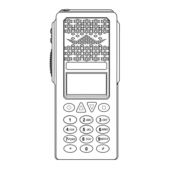
General information 1.7 radio controlS programmable Speaker Side Buttons Side connector microphone alphanumeric display BK RADIO push-to-talk Ch 1 programmed menu items K NG - P 25 171.5 8 5 0 0 M Hz diamond Button liGt menu Square Button... -
Page 13: General Information
General information Status indicators Buttons and labels NOTE: The Diamond, Up Arrow, Down Arrow, and Receiver Signal Strength Square buttons are programmable with PC Radio Editor Software. The programmed functions are Receive Digital, Receive Analog, activated by pressing the associated button. Active rxd, rxa Hold Time Active functions are indicated by a highlighted background. -
Page 14: Radio Tier Versions
WXYZ 1.9 Service information If you need service, contact your local BK Radio dealer equipped to service your radio. If you find it impractical to have service performed by your local dealer, contact BK Radio at the address below: Bk radio attention: customer Service... - Page 15 General information BLANK PAGE Page 1-6 Service Manual - KNG Portables...
-
Page 16: General Information
All information programmed into the radio is maintained even when the battery pack is removed. BK Radio battery packs are available in a variety of capacities and types for special applications. Rechargeable battery packs can be charged separately or while attached to a radio. -
Page 17: Antenna Installation
2.1.3 antenna inStallation NOTE: Transmitting without an antenna could result in damage to your radio. Use RELM/BK Radio approved antennas only. Use of non-qualified or mismatched antennas could result in diminished radio operation. Published radio specifications cannot be guaranteed with non-approved antennas. -
Page 18: Programming P25 Id Unit Call/Receive List
3. Use the keypad to select the desired ID number. (Up to seven digits.) ▼ 4. Press the ‘ENT’ button to save the ID. C a l l 1 C a l l 1 L a b e l 12 3 4 5 6 7 BK Radio Page 2-3... -
Page 19: Programming User Selectable Transmit Tones
installation and programming 2.2.1.2 proGramminG uSer SelectaBle tranSmit toneS The KNG can be pre-programmed with up to 32, user selectable, CTCSS or CDCSS subaudible transmit tones. Tones are selected with the programmed buttons. If enabled, the tones can be programmed via the radio’s keypad. -
Page 20: Programming User Selectable Network Access Codes
U s e r N A C s 1 - $ 2 9 3 2 - $ D 7 E ▲ ▼ N A C 0 1 $ 0 0 0 N A C 0 1 BK Radio Page 2-5... -
Page 21: Programming User Selectable Talkgroup Ids
installation and programming 2.2.1.4 proGramminG uSer SelectaBle talkGroup idS The KNG can be pre-programmed with up to 32, user selectable TGIDs. TDIDs are selected with the programmed buttons. If enabled, the TGIDs can be programmed via the radio’s keypad. to enter tGid list programming: 1. -
Page 22: Programming Channel Parameters
If enabled, channel, zone and global parameters can be programmed using the radio’s keypad. Individual parameters may be blocked from programming access. Check with your RELM/BK Radio dealer or communications officer for information on the programmed functions of your radio. -
Page 23: Channel Label
installation and programming channel label 1. With ‘Chan Label’ highlighted, press the ‘ENT’ button. C h a n L a b e l 2. Press the ‘CLR’ button to clear the label. R x F r e q R x M o d e 3. -
Page 24: Receive Code Guard
S q u e l c h M o d e 4. Press the ‘ESC’ button to return to the Channel Programming menu. → N o r m a l S e l e c t i v e ▲ ▼ BK Radio Page 2-9... -
Page 25: Transmit Frequency
installation and programming transmit frequency 1. With ‘Tx Freq’ highlighted, press the ‘ENT’ button. S q u e l c h M o d e 2. Press the ‘CLR’ button to clear the current frequency. T x F r e q T x M o d e 3. -
Page 26: Transmit Code Guard
U N A C 3 2 Picklist, a “User Picklist Active” notification appear on the display. T X N A C U N A C E n a b l e d U N A C BK Radio Page 2-11... -
Page 27: Talkgroup Id
installation and programming talkgroup id This programs the channels Default TGID value. T x N A C 1. With ‘TGID’ highlighted, press the ‘ENT’ button. T G I D S e c u r e M o d e 2. Press the ‘CLR’ button to clear the currently programmed TGID. ▲... -
Page 28: Encryption Key Lock (Encrypted Models)
Off = Selectable Power, On = Low Power Only. → O f f 3. Press the ‘ENT’ button to set the selection. ▲ ▼ 4. Press the ‘ESC’ button to return to the Channel Programming menu. BK Radio Page 2-13... -
Page 29: Programming Zone Parameters
installation and programming 2.2.1.6 proGramminG Zone parameterS Programmable Zone functions include: Zone Label, Priority 1 Channel, Transmit on Priority 1 Channel, Priority 2 Channel, Automatic-Number- Identification (ANI) settings and Allow/Disallow Cloning. to enter the Zone programming mode: 1. Press the MENU button. Scan C h 1 2. -
Page 30: Priority 1 Channel
BOTH = Keypad Tones and manual ANI. → O f f D T M F O n l y 3. Press the ‘ENT’ button to set the selection. ▲ ▼ 4. Press the ‘ESC’ button to return to the Zone Programming menu. BK Radio Page 2-15... -
Page 31: Automatic Number Identification (Ani) Id
installation and programming Automatic Number Identification (ANI) ID 1. With ‘ANI ID’ highlighted, press the ‘ENT’ button. P r i 2 C h a n 2. Press the ‘CLR’ button to clear the ID. A N I M o d e A N I I D 3. -
Page 32: Programming Global Parameters
P r i 1 C h a n n e l O f f 4. Press the ‘ENT’ button to set the selection. → M a i n 5. Press the ‘ESC’ button to return to the Global Programming menu. ▲ ▼ BK Radio Page 2-17... -
Page 33: Global Priority 1 Zone
installation and programming Global priority 1 Zone 1. With ‘Pri 1 Zone’ highlighted, press the’ENT’ button. P r i 1 C h a n 2. Use the up/down buttons to highlight the Zone of desired P r i 1 Z o n e T x o n P r i 1 Global Priority Channel. -
Page 34: Scan Hold Time
→ K e y p r e s s or the keypad is used. ▲ ▼ 3. Press the ‘ENT’ button to set the selection. 4. Press the ‘ESC’ button to return to the Global Programming menu. BK Radio Page 2-19... -
Page 35: Backlight Duration
installation and programming Backlight duration 1. With ‘Bklight Dur’ highlighted, press the ‘ENT’ button. T X T O T 2. Use the up/down buttons to select the desired Backlight Time Limit. B k l i g h t M o d e B k l i g h t D u r (1 - 6 seconds, Off or Always On) ▲... -
Page 36: Radio Cloning
If “Cloning” is programmed as a menu item, any Source radio (a KNG with the desired radio frequencies and settings) is capable of transferring its program to another KNG of the same frequency range. In addition, information between a KNG-P150 and certain other BK Radio models radio can be cloned. (See “KNG to Legacy Radio Cloning” below.) The radio receiving the program is referred to as the Target. -
Page 37: Kng To Legacy Radio Cloning
The KAA0701 cloning cable will be required in the following procedures. Information programmed in a KNG-P150 portable can be cloned other BK Radio models on a Zone- to-Zone basis. Entire radio cloning is not available between different radio models. Cloning compatible models include: DPHX5102X, GPH5102XP, DPHX-CMD, GPH-CMD, DMH, GMH Plus and most GPH portable models. - Page 38 If picklist selections are assigned in the source radio, and the target radio is not capable of picklist selection, the associated picklist value will be cloned to the target radio. For example, if a channel has a picklist selected NAC whose value is $123, then $123 will be sent to the target radio. BK Radio Page 2-23...
- Page 39 NOTE: Earlier BK Radio models use the term “Group” instead of “Zone”. Connect the KAA0701 Cloning Cable to the side connector of the Source and target radios and power up both radios. On the Target radio select the target zone/group by pressing the [#] key Digital and entering the number of the desired zone/group.
-
Page 40: Legacy Radio To Kng Cloning
2.2.2.3 leGacy radio to knG cloninG The following instructions are based on the DPHX5102X. NOTE: Earlier BK Radio models use the term “Group” instead of “Zone”. The following table shows cloned information when using a KNG-P150 as the Target Radio:... - Page 41 NOTE: To stop the ‘FAIL’ Mode, press [CLR], . command radio model target Selection When using a BK Radio Command (CMD) radio as a cloning source you must designate the target as a G/DPH-CMD not a standard G/DPH. Press...
-
Page 42: Pc Radio Editing
Both Receive and Transmit Network Access Codes (NAC) are required for channels programmed to operate in Digital Mode. NACs can be viewed and programmed as either decimal or hexadecimal numbers. (See Network Access Code.) BK Radio Page 2-27... - Page 43 installation and programming don’t Show empty Zones Each zone can be programmed with zero to sixteen channels. Zones with no channels can be hidden from view by selecting ‘Don’t Show Empty Zones’. Zones that are made up of unprogrammed channels are not considered empty and can not be hidden from view.
-
Page 44: Reading And Writing Radio Information
Tier III - Full Keypad and Display By selecting the proper Tier, under the Options Tab, programmable functions that do not apply to the selected tier will be ‘grayed out’ or blocked from selection. BK RADIO BK RADIO BK RADIO PQRS... -
Page 45: Programming Zone Information
installation and programming Global Data To read only the radio’s global settings select ‘Read Global Information from Radio’ under the ‘Read’ tab at the top of the screen. When reading only the global data, the previously active zone and channel information remains. - Page 46 Global Settings under the ‘Genera’ tab. receive frequency Enter a valid receive frequency. frequency ranges model number valid frequency range P150 136 to 174 MHz. P400 380 to 470 MHz P500 440 to 520 MHz P800 764 to 869 MHz BK Radio Page 2-31...
- Page 47 installation and programming valid frequency increments Frequencies must be devisable by 1.25 kHz as shown. If a frequency that is not divisible kHz Hz by 1.25 kHz is entered the program will not accept it and a message will be displayed. XXX.001250 XXX.002500 Entering a zero for the Receive Frequency will cause the radio’s display to show...
- Page 48 Channels programmed with Transmit frequencies must also contain a Receive frequency. transmit mode Each channel can be programmed for Analog-only operation, Digital-only operation, or Mixed Mode (Analog and Digital) operation. Selecting Mixed Mode for transmit allows the radio to transmit both digital and analog signals. BK Radio Page 2-33...
- Page 49 installation and programming If the channel’s Transmit Mode is programmed for Mixed, the default transmit mode is set by the Transmit Digital Mode soft switch (see Global Controls Tab for control assignment options). Click on the box or use the spacebar to set select the desired operation. A for Analog, D for Digital, or M for Mixed Mode.
- Page 50 When reading a radio, channels with active user selected tones will show “UTXG” followed by the current tone number. Squelch operation For Digital and Mixed Mode channels, a digital squelch operation must be programmed. Click on the box or use the space bar to set select the desired operation. BK Radio Page 2-35...
- Page 51 installation and programming normal Used to mimic analog operation. Signals are only qualified with the programmed receive Network Access Code (NAC). All Talk Group IDs (TGIDs) and P25 Unit IDs are accepted. Selective Used for processing ‘Group Calls’ and ‘Unit-to-Unit Calls’. Users can be separated into Talk Groups with each group having its own TGID.
- Page 52 Click on the box or use the spacebar to select “L” to lock channel in Low power or “-” to allow use of the Hi/Lo power switch. (See the Global Controls screen for switch options.) BK Radio Page 2-37...
-
Page 53: Encryption Channel Settings
installation and programming encryption channel Settings Security The following applies only to radios equipped with the Cryptographic module. Digital channels can be programmed to always transmit encrypted (Enc), always transmit clear (Clr), or to select the Transmit Mode with the Transmit Secure switch (Sw). Analog channels and channels that are set to clear or encrypted, will ignore the Transmit Secure switch. -
Page 54: Zone Settings
APCO Project 25 compatible key fill device such as the Motorola KVL 3000 Plus, using a BK Radio keyloader cable. Use the dropbox to select “O” for channels that will receive OTAR messages, or “-” to disable OTAR on the channel. - Page 55 installation and programming Automatic Number Identification (ANI) On each Zone Settings screen, enter up to 7 digits (0 – 9, A – F) for the ANI ID that will be used when the zone is selected. The Automatic Numeric Identification (ANI) ID number can be used for radio management or transmitted as a DTMF tone burst for ANI purposes.
- Page 56 Code Guard and/or Talkgroup will be searched. NOTE: Channel voting occurs only with Channel Scan and is disabled when Zone Scanning. Channels programmed as Vote channels are treated as normal scan list channels during Zone Scan operation. BK Radio Page 2-41...
-
Page 57: Global Settings
installation and programming 2.2.3.5 GloBal SettinGS The Global Settings Screen allows editing of data that will be used by ALL Channel Zones in the radio, such as the radio’s P25 Unit ID, Talkback Modes, and Soft Switch assignments. To access the Global Settings Screen, click on Global Settings in the left most panel. - Page 58 The green Busy Channel Indicator on the top of the radio glows if there is carrier activity on the selected channel. If the selected channel is a Code Guard channel and the proper Code Guard value is not detected, the Busy Channel Indicator remains on for the duration of the carrier activity and BK Radio Page 2-43...
- Page 59 installation and programming no message is heard. During Scan and Priority Scan operation, the Busy Channel Indicator glows when activity is detected on any channel on the Scan List. When scanning or priority scanning Code Guard channels and activity has been detected, the Busy Channel Indicator glows for the time period necessary to determine if the proper Code Guard value has been received.
- Page 60 Global Priority 1 channel, when operating in the priority scan mode. When receiving activity on a scanned channel the radio will continue monitoring for activity on the assigned priority channels. When activity is detected the radio switches to receive the priority channel. BK Radio Page 2-45...
- Page 61 installation and programming disabled If checked Priority channels are selected as assigned in the radio’s currently selected Channel Zone. (See priority options under Channel Zones) If unchecked priority scan operation is determined by these Global Priority settings: use main channel If checked the Priority 2 channel is selected by the channel select knob.
-
Page 62: Features Tab
If checked, programmers will be prompted to enter the radio’s Administrator Password before writing to the radio via computer. If unchecked, a password is not required to write information to the radio. BK Radio Page 2-47... - Page 63 installation and programming enable nuisance channel delete If checked a Nuisance Channel can be temporarily removed from the Scan List by pressing the programmed nuisance channel button. When the radio is powered down and then back on, the channel will be restored to the scan list. If unchecked, unwanted scan channels must be removed via keypad scan list selection or PC programming.
-
Page 64: Unit Call List Tab
(0 - 100) and press PTT to place the call. Call can be placed to individual radios who’s ID number is not programmed in the list by entering the Unit Call mode and selecting “Enter ID”. BK Radio Page 2-49... -
Page 65: Keypad Editing Lockouts Tab
installation and programming keypad editinG lockoutS taB Keypad editing lockouts pertain only to full keypad models with keypad programming enabled. (See Menus/Controls) All available keypad programmable options can be locked to disallow field programmability of proprietary functions. Any function selected in the Keypad Editing Lockouts screen will not be available when the User Password is used to enter the programming mode. - Page 66 tactical otar radio (Option required) Switch between digital and analog transmit onmixed mode tx digital channels Switch between low transmit power and programmed high tx power power setting (Continued) BK Radio Page 2-51...
-
Page 67: Pick Lists Tab
installation and programming available functions Button Switch menu Enable secure transmit on channels programmed for tx Secure switchable encryption (Requires encryption option) unit call Enable P25 unit-to-unit call mode version Displays internal radio frimware information Remove all encryption keys and radio passwords ... -
Page 68: Encryption Tab
A KVL 3000 Plus Keyloader or equivalent and Keyload Interface Cable are required to program encryption keys to the KNG. BK Radio Page 2-53... -
Page 69: Tactical Otar Tab
installation and programming Enter SLN’s (Storage Location Numbers) in the table that correspond to the CKR’s (Common Key References) of the keys that have been loaded into the radio with the APCO Project 25 compatible keyloader unit. label Program an alphanumeric label for each active encryption key. Security Enable Clear Tx Mode Warning Beep. - Page 70 User Specified - If selected the master radio will prompt the user to select the desired picklist slot prior to sending the key. default picklist target Select the desired picklist target slot. If “Default Pick List Target” is not selected above, this setting will be ignored. BK Radio Page 2-55...
-
Page 71: Encryption Key Fill
2.2.5 tactical otar Setup The BK Radio Tactical OTAR system allows the transfer of a single encryption key, via a specially equipped Key Source radio, to OTAR capable BK Radios. Key Source radios can be programmed with a list of up to 32 keys from which to select. - Page 72 It is recomended that the OTAR channel be set to Always Encrypt (Enc). If the channel is programmed for switchable encryption, the switch must be in the encrypted position when sending or receiving Tacital OTAR keys. BK Radio Page 2-57...
- Page 73 installation and programming If the OTAR channel is to also be used as a communication channel, select the desired encryption key from Encryption Key List. Global Settings Click the “Enable OTAR Operation” box under the” Encryption” tab. Select the “Disable Data Registration” check box under the “Encryption” tab. Drag-and-drop “Tactical OTAR”...
-
Page 74: Target Radio Configuration
Load a Message Authentication Code Traffic Encryption Key (MTEK). The CKR CKR 12345 number of the MTEK must be between 1 and 61439. This number must match ALG: AES-256 the MTEK number programmed in the Source Radio. KID: 1313 LOAD CKR 54321 BK Radio ALG: AES-256 Page 2-59 KID: 2255... - Page 75 CKR 12345 ALG: AES-256 KID: 1313 installation and programming LOAD Load a Data Traffic Encryption Key (DTEK) key. The CKR number of the DTEK CKR 54321 must be between 1 and 61439. This number must match the DTEK number ALG: AES-256 programmed in the Source Radio.
-
Page 76: Tactical Otar Quick Reference
General Failure DTEK Not Found or Not AES MTEK Not Found or Not AES General Failure during Key Wrap Key Not Found for Key Wrap Key to Wrap Key is Not identified as a KEK BK Radio Page 2-61... -
Page 77: Vote Scan Setup
installation and programming 2.2.6 vote Scan Setup Channels in a multicast conventional systems can be added to the scan list and designated as “voted” channels. The KNG radio scans all voted channels and selects the channel with the best signal. If enabled vote scanning takes place whenever the channel scan switch is on. -
Page 78: Ctcss Code Guard Values
Unit-to-Unit transmission (systems without mobile relays, repeaters, remote control, etc.) may use codes from the table. Systems with relays, etc., may use code variations for systems control and operational efficiency. The system operator or engineer should be consulted regarding the operational requirement on such systems. BK Radio Page 2-63... - Page 79 installation and programming BLANK PAGE Page 2-64 Service Manual - KNG Portables...
-
Page 80: Basic Operation
Factory installed options are referenced on the back of the radio. The following list includes options available at the time of printing. Contact RELM Wireless or your BK Radio dealer for information on factory installed option. factory installed options... -
Page 81: Transmit
2. Talk in a normal voice with the microphone one to two inches from your mouth. 3. Release the PTT switch to stop transmitting. BK RADIO If the length of your message exceeds the programmed Time-Out Timer Ch 1 K N G - P 2 5 171. -
Page 82: Code Guard Receive
Analog receptions and transmissions will be indicated by illuminating the A annunciator in addition to the RX or TX annunciator. C h 1 K N G - P 2 5 171. 5 8 5 0 0 M H z uton menu BK Radio Page 3-3... -
Page 83: Mixed Mode Talkback
Radios that have the DES/AES factory option for encryption must have encryption keys loaded with an APCO Project 25 compatible key fill device such as the Motorola KVL 3000 Plus, using a BK Radio keyloader cable. The radio can hold up to 32 AES and/or DES keys. -
Page 84: Transmit Encryption Key Selection
2. Press the ‘YES’ button to zeroize encryption Z e r o i z e N o w ? or press ESC to abort the operation. 3. Hold the ‘ESC’ button to return to normal operation. BK Radio Page 3-5... -
Page 85: Over-The-Air-Rekeying (Otar)
operation If programmed to the Menu button: 1. Press the Menu button. C h a n n e l S c a n 2. Use the up/down buttons to highlight ‘Zeroize Keys’ selection. Z e r o i z e K e y s 3. -
Page 86: Tactical Otar Option (Kza0584)
To view the label and key index press the “#” button. K e y 2 K e y 3 Alternatively the key can be selected directly via the keypad by pressing 1-32. ▲ ▼ ENTER BK Radio Page 3-7... - Page 87 operation Pick Key Index If the “Key Pick List Target” is programmed (see “Target Radio Options” under 1 “Key Source Radio Configuration”) the pick list target screen is displayed. Use the Up/Down buttons to select the desired target key slot. This is the key ▲...
-
Page 88: Scan Operation Options
Voting occurs during channel scan operation and is not valid when scanning multiple zones (Zone Scan). During Zone Scan operation, the designated vote scan channels operate as normal scan channels and are note voted. BK Radio Page 3-9... -
Page 89: Nuisance Channel Delete
operation 3.5.4 nuiSance channel delete If a button on your radio is programmed for Nuisance Channel Delete a channel can be temporarily removed from the Scan List . To temporarily remove a channel from the scan list Press the assigned Nuisance C h 1 [ nuiS ] button... - Page 90 → Z o n e 1 Z o n e 2 ▲ ▼ Z o n e 0 1 P r 1 → C h a n n e l 1 C h a n n e l 2 ▲ ▼ BK Radio Page 3-11...
-
Page 91: Scan List Add/Delete
operation menu operation C h 1 1. Press the assigned Menu button. K N G - P 2 5 171. 5 8 5 0 0 M H z 2. Use the up/down buttons to select ‘Pri Channels’. liGt menu 3. Use the up/down buttons to select the priority channel or zone you wish to edit. -
Page 92: Zone Scan (Zscn)
Z o n e S c n L i s t ▲ ▼ 6. Hold the ‘ESC’ button to return to normal operation. Z o n e S c a n Z O N E 1 + Z O N E 2 ▲ ▼ BK Radio Page 3-13... -
Page 93: Emergency Signalling Options
operation 3.6 emerGency SiGnallinG optionS The KNG portable radio supports P25 Emergency Operation. When Emergency Operation is engaged the radio will transmit the P25 ID of the radio along with the required P25 Emergency information on the channel designated in the “Emergency TX” section of the radio editor software. Only channels programmed for Digital or Mixed Mode transmit can be assigned as the Emergency Channel. - Page 94 10 seconds. Each PTT will send the selected call. K N G - P 2 5 171. 5 8 5 0 0 M H z Press ‘ESC’ to exit Unit-to-Unit mode or press ‘U2U’ to select another caller ID. BK Radio Page 3-15...
-
Page 95: Unit-To Unit Callback
operation receivinG a unit-to-unit call When receiving a unit-to-unit call the beeps and the phone icon is displayed during the reception. C h a n n e l 1 After the message the phone icon will continue flashing to indicate that a unit-to- Z o n e 2 unit call has been received. -
Page 96: Nac (Tnac/Rnac)
5. Press the ‘ENT’ button to set the selection. U s e r N A C s → N A C - 0 1 6. Hold the ‘ESC’ button to return to normal operation. N A C - 0 2 ▲ ▼ BK Radio Page 3-17... -
Page 97: Tgid (Utg)
operation 3.8.3 tGid (utG) Selecting a Talk Group ID from the Pick List will assign the TGID to the currently select channel. All other channels are unaffected. Button operation 1. Turn to the channel you wish to assign the TGID. C h 1 K N G - P 2 5 2. -
Page 98: Keypad Lock
On - Slide the programmed switch toward the front of the radio. Off - Slide the switch up toward the channel select switch. Button operation On - Press the programmed button. Off - Press the button again. BK Radio Page 3-19... -
Page 99: Repeater Talkaround (Ta)
operation menu operation 1. Press the assigned Menu button. C h a n n e l S c a n 2. Use the up/down buttons to select ‘Monitor’. M o n i t o r P R I S c a n 3. -
Page 100: Surveillance Mode (Surv)
6. Use the up/down arrows to select the desires squelch point. S q u e l c h A d j u s t 7. Press ‘ENT’ to set the selection and return to normal operating mode. ▲ ▼ BK Radio Page 3-21... -
Page 101: Tx Digital (Txd)
operation 3.9.7 tx diGital (txd) When the TXD is on, channels programmed for mixed-mode transmit will C h 1 transmit in digital mode. When off, mixed-mode channels transmit in analog K N G - P 2 5 mode. When transmitting in digital mode the display shows ‘D’ behind the TX 171. -
Page 102: Zone Select (Zon)
4. Press ‘ENT’ to set the zone. S e l e c t Z o n e Z o n e # Z O N E L A B E L ▲ ▼ BK Radio Page 3-23... - Page 103 operation Page 3-24 Service Manual - KNG Portables...
-
Page 104: Introduction
4.1 introduction This section contains a description of equipment and a theory of operation for the BK Radio KNG Series APCO Project 25 digital radio. To aid in understanding the operation of the equipment, schematic diagrams are found in Section VI of this manual. -
Page 105: Rf Board
theory of operation Baseband Signal processor TCXO 19.6608 MHz TX AUDIO SPEAKER AUDIO BASEBAND SIGNAL PROCESSOR DISC CONTROL / AUDIO DATA BUS µ TO CORE (1) Baseband Signal Processor - Implements filters, tone generators, and other signal processing algorithms required for analog and digital modes of operation. (2) TCXO –... -
Page 106: Rf Input/Output
Coarse Tune Coarse Tune Tx Audio RX VCO TX VCO 181-219 MHz (P150) 136-174 MHz (P150) Digital From uP 290-380 MHz (P400) 380-470 MHz (P400) Potentiometer 350-430 MHz (P500) 440-520 MHz (P500) Control Synthesizer Block diagram BK Radio Page 4-3... -
Page 107: Transmitter
theory of operation The temperature compensated crystal oscillator (TCXO) serves as a stable frequency reference over the operating temperature of the radio. The Synthesizer IC contains programmable counters to divide and compare the VCO frequency from the feedback loop to the TCXO reference frequency and adjust the VCO control voltage in such a way that the VCO maintains a stable output frequency. - Page 108 2nd IF Control Logic 2.304 MHz Decimation Filter Mixer Formatting / To DSP TCXO Reference 19.6608 MHz Clock Synthesizer LO Synthesizer Clock VCO LO VCO Loop Filter Loop Filter 42.696 MHz 18.432 MHz vhf receiver Block diagram BK Radio Page 4-5...
-
Page 109: Receiver
theory of operation Tunable 2nd Tunable 1st Tuanble Pre Selector Filter Pre Selector Filter Crystal Filter Impedance 380-470 MHz (P400) 380-470 MHz (P400) Low Noise Variable 90MHz Harmonic Antenna Match Pre-Amplifier 440-520 MHz (P500) 440-520 MHz (P500) Gain IF Amp Filter Switch Mixer... - Page 110 The bits are then formatted and stored in a buffer in preparation for transfer via the SSI to the radio’s microprocessor. Ultimately, the sampled data is transferred to the microprocessor at 19.2 k samples per second with 16 bits of data per sample. BK Radio Page 4-7...
- Page 111 theory of operation Page 4-8 Service Manual - KNG Portables...
-
Page 112: Introduction
5.3 aliGnment procedureS All alignment functions in KNG portable radios are performed electronically. You will need the KNG Editor Software and programming cable, available from BK Radio. Refer to the KNG Editor Help file for more details on using the program. -
Page 113: Alignment Order
maintenance To enter the tuning section of the editor click the Tune icon, click “Tune” in the menu bar or press Alt+F. R e m o t e When the radio enters the tuning mode “Remote Programming Mode” will be P r o g r a m m i n g displayed on the radio’s LCD. -
Page 114: Transmit Power Levels
“Squelch Adjust” is assigned to a radio button or menu item. (See “Installation and Programming section of this manual.) Connect an RF Generator tuned to the frequency indicated in the program at -47 dBm BK Radio Page 5-3... -
Page 115: Vote Scan
maintenance Set the Deviation to 3kHz to set the wideband preset squelch or 1.5 kHz to set the narrowband preset squelch. Adjust the radio volume knob for rated audio output Reduce the input signal to achieve 8 dB SINAD Click “Found 8db SINAD” to write the setting to the radio Clicking “Abort”... -
Page 116: Systems Board Assembly
Shields Inspect covers and shields for punctures, deep dents, and badly worn surfaces. Also check for damaged fastener devices, corrosion, and damage to finish. BK Radio Page 5-5... -
Page 117: Cleaning
maintenance flex circuits Inspect flex circuits for punctures and badly worn surfaces. Check for broken traces, especially near the solder contact points. fuse Inspect for blown fuse and check for loose solder joints. insulators Inspect insulators for evidence of damage, such as broken or chipped edges, burned areas and presence of foreign matter. -
Page 118: Repair
5.6 equipment Setup diaGramS TEST BOX GROUND 10 F 16 VDC 2KΩ AUDIO MIC AUDIO SOURCE 8Ω LOAD SPEAKER AUDIO SINAD INPUT RADIO 50Ω LOAD/ EXT ANTENNA ANTENNA RF POWER METER JACK figure 5-1 test Box Setup BK Radio Page 5-7... - Page 119 maintenance FREQUENCY MODULATION RADIO COUNTER METER COMMUNICATIONS TEST SET (SERVICE MONITOR) AUDIO 50 OHM RF IN LOAD RF POWER METER TEST AUDIO GENERATOR OPTIONAL 10 VDC ANTENNA MIC. AUDIO REGULATED POWER SUPPLY RADIO figure 5-2 transmitter tests Setup OPTIONAL RADIO COMMUNICATIONS AUDIO TONE...
- Page 120 Parts Lists for all major assemblies arranged from the Final Assembly down to an individual part level. Each List is followed by the corresponding Assembly Drawing (if required), Schematic Diagram and Parts Placement. Parts itemized in the various lists meet BK Radio’s design specifications and are the recommended replacement parts.
-
Page 121: System Board
final assembly illustrated parts list 6.4 interconnect diaGram Accessory Connector 16 17 Flex Circuit 1700-60280-201 SYN CLK 17 18 SYN DATA -SYN CS LATCH LOCK DETECT RX AUDIO + RX AUDIO - DPTT -DACS CS 3.3 V SPI MISO DATA X2/CLK IN SPI CLK SPI MOSI DATA... - Page 122 SCREW, THUMB, COVER, SIDE-CONNECTOR ITM 9 2820-30903-034 SCREW-METRIC MACHINE, M2x.4x4.5,PH,T,SS QTY 4 ITM 10 1602-31004-500 TAPE-FOAM, B-B FLEX CONNECTOR QTY 4 ITM 11 1700-60284-200 FLEX CIRCUIT, BOARD TO BOARD ITM 12 KAA0400 BELT CLIP ASSY, KNG BK Radio Page 6-3...
-
Page 123: Final Assembly
final assembly illustrated parts list BLANK PAGE Page 6-4 Service Manual - KNG Portables... - Page 124 1. Flex Strip connects to J1 on RX/TX Board Final Assembly Ref. 0008-xxxxx-xxx THIS DRAWING IS PROPERTY OF RELM AND SHALL NOT BE REPRODUCED, COPIED OR USED AS THE BASIS FOR THE MANUFACTURE OR SALE OF PRODUCTS WITHOUT PERMISSION BK Radio Page 6-5...
- Page 125 final assembly illustrated parts list BLANK PAGE Page 6-6 Service Manual - KNG Portables...
- Page 126 ITM 3 2003-30964-302 ITM 4 2811-30995-600 Scr,Plas, Thread Roll,Torx,M2x.79,5mm,3.5mm Hd ITM 5 0008-30976-400 Assembly, Systems Board ITM 6 2509-30985-900 Inlay, Collar ITM 7 2513-30992-200 Inlay, Toggle-Switch ITM 8 Included in ITM 1 Speaker, 40mm, 8 Ohm BK Radio Page 6-7...
-
Page 127: Front Assembly
Inlay, P500 ITM 3 xxxx-xxxxx-xxx Inlay, P800 ITM 4 1411-30985-300 ITM 5 0008-30976-400 Assembly, Systems Board ITM 6 2509-30985-900 Inlay, Collar ITM 7 2513-30992-200 Inlay, Toggle-Switch ITM 8 Included in ITM 1 Speaker, 40mm, 8 Ohm BK Radio Page 6-7... - Page 128 final assembly illustrated parts list BLANK PAGE Page 6-8 Service Manual - KNG Portables...
- Page 129 *Assembly includes: Display lense and keypad, on applicable models, speaker and orange top button THIS DRAWING IS PROPERTY OF RELM AND SHALL Front Assembly Ref. 0008-30994-5xx NOT BE REPRODUCED, COPIED OR USED AS THE BASIS FOR THE MANUFACTURE OR SALE OF PRODUCTS WITHOUT PERMISSION BK Radio Page 6-9...
- Page 130 final assembly illustrated parts list BLANK PAGE Page 6-10 Service Manual - KNG Portables...
-
Page 131: Back Assembly
2811-30995-500 SCR, METAL THREAD ROLLIN, M2x4, 4MM, 3.5mm QTY 7 ITM 6 2856-20003-303 Nut, Spanner, M6x0.75 (.350 x .080) QTY 2 ITM 7 2858-20003-403 Nut, Spanner, 1/4-36 (.350 x .080) ITM 8 1406-30995-200 GORTEX-VENT, Gore VE40308 BK Radio Page 6-11... - Page 132 final assembly illustrated parts list BLANK PAGE Page 6-12 Service Manual - KNG Portables...
- Page 133 THIS DRAWING IS PROPERTY OF RELM WIRELESS AND SHALL NOT BE REPRODUCED, COPIED OR Back Assembly Rev. 0008-30976-501 USED AS THE BASI FOR MANUFACTURE OR SALE OF PRODUCT WITHOUT PERMISSION BK Radio Page 6-13...
- Page 134 final assembly illustrated parts list BLANK PAGE Page 6-14 Service Manual - KNG Portables...
-
Page 135: Systems Assembly
1700-60284-200 FLEX CIRCUIT, BOARD TO BOARD, P-150 ITM 8 2800-31000-500 SPACER, MIC, KNG-P SERIES ITM 9 1310-20000-500 MIC, ELEMENT, POM-3542P-R, KNG ITM 10 1411-40001-800 BUSHING, MIC, MOLDED, EP ITM 11 1411-40001-800 GASKET, FOAM, MIC, KNG-P SERIES BK Radio Page 6-15... - Page 136 Systems assembly illustrated parts list BLANK PAGE Page 6-16 Service Manual - KNG Portables...
- Page 137 SYSTEMS BOARD DURING TEST. FRONT SIDE BACK SIDE THIS DRAWING IS PROPERTY OF RELM AND SHALL Systems Board Assembly Ref. 0008-30976-400 NOT BE REPRODUCED, COPIED OR USED AS THE BASIS FOR THE MANUFACTURE OR SALE OF PRODUCTS WITHOUT PERMISSION BK Radio Page 6-17...
- Page 138 Systems assembly illustrated parts list BLANK PAGE Page 6-18 Service Manual - KNG Portables...
-
Page 139: Systems Board
1570-03103-261 Cap,Cp,.01uF,5%,X7R,16V,0402 1570-03103-261 Cap,Cp,.01uF,5%,X7R,16V,0402 1570-03103-261 Cap,Cp,.01uF,5%,X7R,16V,0402 1570-03103-261 Cap,Cp,.01uF,5%,X7R,16V,0402 1570-03103-261 Cap,Cp,.01uF,5%,X7R,16V,0402 1570-01226-788 Cp,Cp,22uF,X5R,20%,6.3V,0805 1570-01475-772 Cp,Cp,4.7uF,X5R,10%,25V,0805 1570-01475-772 Cp,Cp,4.7uF,X5R,10%,25V,0805 1570-00105-772 Cp,Cp,1uF,X5R,10%,25V,0603 1570-03100-163 Cp,Cp,10pF,NPO,5%,50V,0402 1570-03102-163 Cp,Cap,1000PF,5%,NPO,50V,0402 1570-01226-788 Cp,Cp,22uF,X5R,20%,6.3V,0805 1570-01475-772 Cp,Cp,4.7uF,X5R,10%,25V,0805 1570-01475-772 Cp,Cp,4.7uF,X5R,10%,25V,0805 1570-00105-772 Cp,Cp,1uF,X5R,10%,25V,0603 1570-03100-163 Cp,Cp,10pF,NPO,5%,50V,0402 1570-03102-163 Cp,Cap,1000PF,5%,NPO,50V,0402 1570-00475-788 Cp,Cp,4.7uF,X5R,20%,6.3V,0603 BK Radio Page 6-19... - Page 140 Systems Board illustrated parts list Parts List, 30976-400, Systems Board, KNG Portable reference part number description notes 1570-03104-777 Cap,Cp,0.1uF,10%,X5R,10V,0402 1570-01226-788 Cp,Cp,22uF,X5R,20%,6.3V,0805 1570-00475-788 Cp,Cp,4.7uF,X5R,20%,6.3V,0603 1570-00475-788 Cp,Cp,4.7uF,X5R,20%,6.3V,0603 1570-03102-163 Cp,Cap,1000PF,5%,NPO,50V,0402 1570-00225-771 Cp,Cp,2.2uF,X5R10%,16V,0603 1570-00225-771 Cp,Cp,2.2uF,X5R10%,16V,0603 1570-00475-788 Cp,Cp,4.7uF,X5R,20%,6.3V,0603 1570-03102-163 Cp,Cap,1000PF,5%,NPO,50V,0402 1570-00225-771 Cp,Cp,2.2uF,X5R10%,16V,0603 1570-00225-771 Cp,Cp,2.2uF,X5R10%,16V,0603 1570-03102-163 Cp,Cap,1000PF,5%,NPO,50V,0402 1570-00105-772 Cp,Cp,1uF,X5R,10%,25V,0603...
- Page 141 C113 1570-03150-163 Cap,CP,15pF,NPO,5%,50V,0402 C115 1570-03102-163 Cp,Cap,1000PF,5%,NPO,50V,0402 C116 1570-03102-163 Cp,Cap,1000PF,5%,NPO,50V,0402 C117 1570-03102-163 Cp,Cap,1000PF,5%,NPO,50V,0402 C118 1570-03102-163 Cp,Cap,1000PF,5%,NPO,50V,0402 C119 1570-03102-163 Cp,Cap,1000PF,5%,NPO,50V,0402 C120 1570-03102-163 Cp,Cap,1000PF,5%,NPO,50V,0402 C121 1570-03102-163 Cp,Cap,1000PF,5%,NPO,50V,0402 C122 1570-03102-163 Cp,Cap,1000PF,5%,NPO,50V,0402 C123 1570-03470-163 Cap,Cp,47pF,NPO,5%,50V,0402 C125 1570-03470-163 Cap,Cp,47pF,NPO,5%,50V,0402 C126 1570-00105-772 Cp,Cp,1uF,X5R,10%,25V,0603 BK Radio Page 6-21...
- Page 142 Systems Board illustrated parts list Parts List, 30976-400, Systems Board, KNG Portable reference part number description notes C127 1570-03103-261 Cap,Cp,.01uF,5%,X7R,16V,0402 C128 1570-03103-261 Cap,Cp,.01uF,5%,X7R,16V,0402 C129 1570-03103-261 Cap,Cp,.01uF,5%,X7R,16V,0402 C130 1570-03103-261 Cap,Cp,.01uF,5%,X7R,16V,0402 C131 1570-03103-261 Cap,Cp,.01uF,5%,X7R,16V,0402 C132 1570-03103-261 Cap,Cp,.01uF,5%,X7R,16V,0402 C133 1570-03104-777 Cap,Cp,0.1uF,10%,X5R,10V,0402 C134 1570-00225-771 Cp,Cp,2.2uF,X5R10%,16V,0603 C135 1570-03471-163...
- Page 143 LED,Single Color,CL280YG 4810-30900-205 LED,Single Color,CL280YG 4810-30900-205 LED,Single Color,CL280YG 4828-30513-304 Di,ESD,PESD15VS1UB,SOD-523 4824-30533-552 Di,Sil,Switch-Dual,DAN222M,VMD3 4828-30513-204 DI,ESD,ESD5Z6.0T1, SOD-523 4828-30513-204 DI,ESD,ESD5Z6.0T1, SOD-523 4828-30513-204 DI,ESD,ESD5Z6.0T1, SOD-523 4828-30513-204 DI,ESD,ESD5Z6.0T1, SOD-523 4828-30513-202 DI,ESD,ESD5Z3.3T1, SOD-523 4828-30513-204 DI,ESD,ESD5Z6.0T1, SOD-523 4828-30513-204 DI,ESD,ESD5Z6.0T1, SOD-523 2503-02121-505 Bead,Fer.,120_OHMS@100MHz,200ma,0402 2503-02121-505 Bead,Fer.,120_OHMS@100MHz,200ma,0402 BK Radio Page 6-23...
- Page 144 Systems Board illustrated parts list Parts List, 30976-400, Systems Board, KNG Portable reference part number description notes 2503-04600-439 Bead,Fer.,60_Ohms,500mA,0603 2503-04600-439 Bead,Fer.,60_Ohms,500mA,0603 2503-04600-439 Bead,Fer.,60_Ohms,500mA,0603 2503-04600-439 Bead,Fer.,60_Ohms,500mA,0603 2503-02121-505 Bead,Fer.,120_OHMS@100MHz,200ma,0402 FB10 2503-02121-505 Bead,Fer.,120_OHMS@100MHz,200ma,0402 FB11 2503-02121-505 Bead,Fer.,120_OHMS@100MHz,200ma,0402 FB12 2503-02121-505 Bead,Fer.,120_OHMS@100MHz,200ma,0402 FB13 2503-02121-505 Bead,Fer.,120_OHMS@100MHz,200ma,0402 FB14 2503-04300-438 Bead,Fer.,30_Ohms,1000mA,0603 FB15...
- Page 145 4734-01001-311 Res,CP,1.00K,1%,1/16W,0402 4734-01001-311 Res,CP,1.00K,1%,1/16W,0402 4734-05623-311 Res,Cp,562K,1%,1/16W,0402 4734-01003-311 Res,CP,100K,1%,1/16W,0402 4734-01003-311 Res,CP,100K,1%,1/16W,0402 4734-02009-311 Res,Cp,20_Ohms,1/16W,1%,0402 4734-02009-311 Res,Cp,20_Ohms,1/16W,1%,0402 4734-02009-311 Res,Cp,20_Ohms,1/16W,1%,0402 4734-02009-311 Res,Cp,20_Ohms,1/16W,1%,0402 4734-03013-311 Res,Cp,301K,1%,1/16W,0402 4734-39102-454 Res,Cp,91K,0.1%,1/16W,0402 4734-32492-454 Res,Cp,24.9K,0.1%,1/16W,0402 4734-08062-311 Res,Cp,80.6K,1%,1/16W,0402 4734-04022-311 Res,Cp,40.2K,1%,1/16W,0402 4734-03012-311 Res,CP,30.1K,1%,1/16W,0402 4734-03012-311 Res,CP,30.1K,1%,1/16W,0402 4734-03012-311 Res,CP,30.1K,1%,1/16W,0402 4734-03012-311 Res,CP,30.1K,1%,1/16W,0402 BK Radio Page 6-25...
- Page 146 Systems Board illustrated parts list Parts List, 30976-400, Systems Board, KNG Portable reference part number description notes 4734-01001-311 Res,CP,1.00K,1%,1/16W,0402 4734-01001-311 Res,CP,1.00K,1%,1/16W,0402 4734-01003-311 Res,CP,100K,1%,1/16W,0402 4734-03011-311 Res,CP,3.01K,1%,1/16W,0402 4734-01002-311 Res,CP,10K,1%,1/16W,0402 4734-01000-311 Res,Cp,100_ohm,1%,1/16W,0402 4734-01000-311 Res,Cp,100_ohm,1%,1/16W,0402 4735-20102-231 Res,Cp,8 X 1K Ntwrk,5%,1/16W 4734-02212-311 Res,CP,22.1K,1%,1/16W,0402 4735-20101-231 Res,Cp,24.9K,0.1%,1/16W,0402 4734-02212-311 Res,CP,22.1K,1%,1/16W,0402 4734-02673-311...
- Page 147 4734-01002-311 Res,CP,10K,1%,1/16W,0402 4734-02673-311 Res,Cp,267k,1/16W,1%,0402 4734-01003-311 Res,CP,100K,1%,1/16W,0402 4734-02002-311 Res,Cp,20K,1%,1/16W,0402 4734-01073-311 Res,Cp,107K,1%,1/16W,0402 4734-01001-311 Res,CP,1.00K,1%,1/16W,0402 R100 4734-00000-008 Res,Cp,0_Ohms(Jumper),1/16W,1A,0402 R101 4734-01001-311 Res,CP,1.00K,1%,1/16W,0402 R102 4734-01001-311 Res,CP,1.00K,1%,1/16W,0402 R103 4734-02009-311 Res,Cp,20_Ohms,1/16W,1%,0402 R104 4734-02009-311 Res,Cp,20_Ohms,1/16W,1%,0402 R105 4734-01003-311 Res,CP,100K,1%,1/16W,0402 R106 4734-01003-311 Res,CP,100K,1%,1/16W,0402 R107 4734-01003-311 Res,CP,100K,1%,1/16W,0402 BK Radio Page 6-27...
- Page 148 Systems Board illustrated parts list Parts List, 30976-400, Systems Board, KNG Portable reference part number description notes R108 4734-01001-311 Res,CP,1.00K,1%,1/16W,0402 R109 4734-03323-311 Res,Cp,332K,1%,1/16W,0402 R110 4734-03323-311 Res,Cp,332K,1%,1/16W,0402 R111 4734-03323-311 Res,Cp,332K,1%,1/16W,0402 R112 4734-01000-311 Res,Cp,100_ohm,1%,1/16W,0402 R113 4734-01003-311 Res,CP,100K,1%,1/16W,0402 R114 4734-01004-311 Res,Cp,1M,1%,1/16W,0402 R115 4734-01003-311 Res,CP,100K,1%,1/16W,0402 R116 4734-01001-311...
- Page 149 IC,Uni-Direct,Xlator,FXLP34P5X,SC70-5 3134-30927-202 IC,BTL_AUD_AMP,2.65W,NCP2820,FLP-CHP 3134-30950-402 IC,DC/DC,Invert,LT1617ES5-1,SOT23-5 3134-30950-602 IC,16-BIT I/O EXPANDER, MCP23017, QFN 4828-30513-105 Di, TVS, Array, RClamp0504F, SC-70 6L 4828-30513-105 Di, TVS, Array, RClamp0504F, SC-70 6L 4828-30513-105 Di, TVS, Array, RClamp0504F, SC-70 6L 3134-30950-302 IC,REG,ADJ,LDO,50ma,TPS71501,SC70 3134-30950-302 IC,REG,ADJ,LDO,50ma,TPS71501,SC70 BK Radio Page 6-29...
- Page 150 Systems Board illustrated parts list Parts List, 30976-400, Systems Board, KNG Portable reference part number description notes 3134-30950-406 IC,REG,VLDO,ADJ,300MA,LTC3025,DC6 3134-30670-625 IC,SW,USB 2.O,TS3USB31,QFN-RSE 2390-30957-104 TCXO,19.6608MHz,+/-2.5PPM, 2.5x3.2mm,SMD 2384-30918-102 Xtal,MS1V-T1K,32.768KHz,12.5pF.SMD Page 6-30 Service Manual - KNG Portables...
- Page 151 Systems Board Systems Board THIS DRAWING IS PROPERTY OF RELM AND SHALL NOT BE Ref. 8888-30976-400 REPRODUCED, COPIED OR USED AS THE BASIS FOR THE MANUFACTURE OR SALE OF PRODUCTS WITHOUT PERMISSION BK Radio Page 6-31...
- Page 152 Systems Board illustrated parts list BLANK PAGE Page 6-32 Service Manual - KNG Portables...
- Page 153 Systems Board Systems Board Ref. 3333-30976-400 Sheet 1 of 5 BK Radio Page 6-33...
- Page 154 Systems Board illustrated parts list BLANK PAGE Page 6-34 Service Manual - KNG Portables...
- Page 155 Systems Board Systems Board Ref. 3333-30976-400 Sheet 2 of 5 BK Radio Page 6-35...
- Page 156 Systems Board illustrated parts list BLANK PAGE Page 6-36 Service Manual - KNG Portables...
- Page 157 Systems Board Systems Board Ref. 3333-30976-400 Sheet 3 of 5 BK Radio Page 6-37...
- Page 158 Systems Board illustrated parts list BLANK PAGE Page 6-38 Service Manual - KNG Portables...
- Page 159 Systems Board Systems Board Ref. 3333-30976-400 Sheet 4 of 5 BK Radio Page 6-39...
- Page 160 Systems Board illustrated parts list BLANK PAGE Page 6-40 Service Manual - KNG Portables...
- Page 161 Systems Board Systems Board Ref. 3333-30976-400 Sheet 5 of 5 BK Radio Page 6-41...
- Page 162 Systems Board illustrated parts list BLANK PAGE Page 6-42 Service Manual - KNG Portables...
-
Page 163: Rx/Tx Assembly
ITM 10 2508-30987-600 SHIELD-LID, MIXER QTY 2 ITM 11 2508-30987-300 SHIELD-LID, IF QTY 2 ITM 12 2508-30988-200 SHIELD-LID, VCO QTY 2 ITM 13 2508-30987-900 SHIELD-LID, SYNTH QTY 2 ITM 14 1601-30999-000 TAPE, FOAM, 3/4” QTY 4 BK Radio Page 6-43... - Page 164 rx/tx assembly illustrated parts list BLANK PAGE Page 6-44 Service Manual - KNG Portables...
- Page 165 This shield is bridged to the Front-End shield (ITEM 16) via the shield bridge (ITEM 21) and secured by solder. RX/TX Assembly Rev. 0008-30976-502 THIS DRAWING IS PROPERTY OF RELM AND SHALL NOT BE REPRODUCED, COPIED OR USED AS THE BASIS FOR THE MANUFACTURE OR SALE OF PRODUCTS WITHOUT PERMISSION BK Radio Page 6-45...
- Page 166 rx/tx assembly illustrated parts list BLANK PAGE Page 6-46 Service Manual - KNG Portables...
-
Page 167: Rx/Tx Boards
1570-03105-778 Cp,Cp,1uF,X5R,10%,6.3V,0402 1570-03105-778 Cp,Cp,1uF,X5R,10%,6.3V,0402 1570-03105-778 Cp,Cp,1uF,X5R,10%,6.3V,0402 1570-03102-163 Cp,Cap,1000PF,5%,NPO,50V,0402 1570-03102-163 Cp,Cap,1000PF,5%,NPO,50V,0402 1570-03102-163 Cp,Cap,1000PF,5%,NPO,50V,0402 1570-03105-778 Cp,Cp,1uF,X5R,10%,6.3V,0402 1570-03105-778 Cp,Cp,1uF,X5R,10%,6.3V,0402 1570-03105-778 Cp,Cp,1uF,X5R,10%,6.3V,0402 1573-02470-153 Cap,Cp,47pF,S,2%,250V,0603 1573-01270-162 Cap,Cp,27pF,S,5%,50V,0402 1573-01100-162 Cap,Cp,10pF,S,5%,50V,0402 1573-02101-153 Cap,Cp,100pF,S,2%,250V,0603 1573-01300-161 Cap,Cp,30pF,S,5%,25V,0402 1570-03102-163 Cp,Cap,1000PF,5%,NPO,50V,0402 1570-03104-771 Cp,Cp,.1uF,X5R,10%,16V,0402 1573-01759-122 Cap,Cp,7.5pF,S,.+/-.10pF,50V,0402 1570-03102-163 Cp,Cap,1000PF,5%,NPO,50V,0402 BK Radio Page 6-47... - Page 168 rx/tx assembly illustrated parts list Parts List, 30976-500, RX/TX Board, P150 reference part number description notes 1570-03104-771 Cp,Cp,.1uF,X5R,10%,16V,0402 1570-03105-778 Cp,Cp,1uF,X5R,10%,6.3V,0402 1570-03103-261 Cap,Cp,.01uF,5%,X7R,16V,0402 1570-03224-778 Cap,Cp,.22uF,X5R,10%,6.3V,0402 1573-02399-133 Cp,Cap,3.9pF,S,+/-.25pF,250V,0603 1573-02829-133 Cap,Cp,8.2pF,S,.+/-.25pF,250V,0603 1573-02300-153 Cap,Cp,30pF,S,2%,250V,0603 1573-02300-153 Cap,Cp,30pF,S,2%,250V,0603 1573-02150-153 Cap,Cp,15pF,S,2%,250V,0603 1573-02110-153 Cap,Cp,11pF,S,2%,250V,0603 1573-02360-153 Cap,Cp,36pF,S, 2%,250V,0603 1573-02470-153 Cap,Cp,47pF,S,2%,250V,0603 1573-02110-153 Cap,Cp,11pF,S,2%,250V,0603...
- Page 169 C111 1570-03332-273 Cap,Cp,3300pF,X7R,10%,50V,0402 C112 1570-03102-163 Cp,Cap,1000PF,5%,NPO,50V,0402 C113 1573-02560-163 Cap,Cp,56pF,S,5%,250V,0603 C114 1570-00221-143 Cap,Cp,220pF,NPO,1%,50V,0603 C115 1573-02470-153 Cap,Cp,47pF,S,2%,250V,0603 C116 1570-03154-777 Cap,Cp,.15uF,X5R,10%,10V,0402 C117 1570-03759-113 Cap,CP,7.5pF,NPO,+/-.25pF,50V,0402 C118 1570-03102-163 Cp,Cap,1000PF,5%,NPO,50V,0402 C119 1570-03104-771 Cp,Cp,.1uF,X5R,10%,16V,0402 C120 1570-03103-261 Cap,Cp,.01uF,5%,X7R,16V,0402 C121 1570-03102-163 Cp,Cap,1000PF,5%,NPO,50V,0402 C122 1570-03102-163 Cp,Cap,1000PF,5%,NPO,50V,0402 BK Radio Page 6-49...
- Page 170 rx/tx assembly illustrated parts list Parts List, 30976-500, RX/TX Board, P150 reference part number description notes C123 1570-03104-771 Cp,Cp,.1uF,X5R,10%,16V,0402 C124 1570-03102-163 Cp,Cap,1000PF,5%,NPO,50V,0402 C126 1570-03104-771 Cp,Cp,.1uF,X5R,10%,16V,0402 C127 1570-03102-163 Cp,Cap,1000PF,5%,NPO,50V,0402 C128 1570-03102-163 Cp,Cap,1000PF,5%,NPO,50V,0402 C129 1570-03102-163 Cp,Cap,1000PF,5%,NPO,50V,0402 C130 1570-03102-163 Cp,Cap,1000PF,5%,NPO,50V,0402 C131 1570-03102-163 Cp,Cap,1000PF,5%,NPO,50V,0402 C132 1570-03470-163 Cap,Cp,47pF,NPO,5%,50V,0402...
- Page 171 1570-03220-163 Cap,Cp,22pF,5%,NPO,50V,0402 C200 1570-03220-163 Cap,Cp,22pF,5%,NPO,50V,0402 C202 1570-03102-163 Cp,Cap,1000PF,5%,NPO,50V,0402 C205 1570-03181-162 Cp,Cap,180 PF,NPO,5%,0402 C206 1573-02390-153 Cap,Cp,39pF,S,2%,250V,0603 C207 1573-02390-153 Cap,Cp,39pF,S,2%,250V,0603 C601 1570-03102-163 Cp,Cap,1000PF,5%,NPO,50V,0402 C605 1570-03102-163 Cp,Cap,1000PF,5%,NPO,50V,0402 C606 1570-03105-778 Cp,Cp,1uF,X5R,10%,6.3V,0402 C607 1570-03103-261 Cap,Cp,.01uF,5%,X7R,16V,0402 C614 1570-03150-163 Cap,CP,15pF,NPO,5%,50V,0402 C615 1570-01106-788 Cp,Cp,10uF,X5R,20%,6.3V,0805 BK Radio Page 6-51...
- Page 172 rx/tx assembly illustrated parts list Parts List, 30976-500, RX/TX Board, P150 reference part number description notes C616 1570-03103-261 Cap,Cp,.01uF,5%,X7R,16V,0402 C617 1570-03150-163 Cap,CP,15pF,NPO,5%,50V,0402 C618 1570-01106-788 Cp,Cp,10uF,X5R,20%,6.3V,0805 C619 1570-03470-163 Cap,Cp,47pF,NPO,5%,50V,0402 C620 1570-03470-163 Cap,Cp,47pF,NPO,5%,50V,0402 C621 1570-03470-163 Cap,Cp,47pF,NPO,5%,50V,0402 C622 1570-03102-163 Cp,Cap,1000PF,5%,NPO,50V,0402 C623 1570-03102-163 Cp,Cap,1000PF,5%,NPO,50V,0402 C624 1570-03102-163 Cp,Cap,1000PF,5%,NPO,50V,0402...
- Page 173 Bead,Fer.,120_OHMS@100MHz,200ma,0402 2503-02121-505 Bead,Fer.,120_OHMS@100MHz,200ma,0402 2503-02121-505 Bead,Fer.,120_OHMS@100MHz,200ma,0402 2503-02121-505 Bead,Fer.,120_OHMS@100MHz,200ma,0402 2503-02121-505 Bead,Fer.,120_OHMS@100MHz,200ma,0402 FB10 2503-02121-505 Bead,Fer.,120_OHMS@100MHz,200ma,0402 FB11 2503-02121-505 Bead,Fer.,120_OHMS@100MHz,200ma,0402 FB12 2503-20022-200 Ferrite,Bead,Surfc,Mt FB13 2503-02121-505 Bead,Fer.,120_OHMS@100MHz,200ma,0402 FB14 2503-02121-505 Bead,Fer.,120_OHMS@100MHz,200ma,0402 FB15 2503-02121-505 Bead,Fer.,120_OHMS@100MHz,200ma,0402 FB16 2503-02121-505 Bead,Fer.,120_OHMS@100MHz,200ma,0402 FB17 2503-20022-200 Ferrite,Bead,Surfc,Mt FB18 2503-04600-439 Bead,Fer.,60_Ohms,500mA,0603 BK Radio Page 6-53...
- Page 174 rx/tx assembly illustrated parts list Parts List, 30976-500, RX/TX Board, P150 reference part number description notes FB19 2503-20022-200 Ferrite,Bead,Surfc,Mt FB20 2503-02121-505 Bead,Fer.,120_OHMS@100MHz,200ma,0402 FB21 2503-02121-505 Bead,Fer.,120_OHMS@100MHz,200ma,0402 FB601 2503-02121-505 Bead,Fer.,120_OHMS@100MHz,200ma,0402 FB603 2503-02121-505 Bead,Fer.,120_OHMS@100MHz,200ma,0402 2705-20022-701 FLTR,X'TAL,45MHz,+/-7.5KHz,4p,5x7mm,SMD 2105-50575-602 CONN,40-PIN,HOR.,0.5mm,SMD 2105-60455-300 CONN, BATTERY 2105-30969-100 Conn. SMA,Jack, RT Angle,PC Mount 1812-56003-050 Ind,Cp,56nH,5%,1008CS 1812-12102-020...
- Page 175 Xstr,NPN,SILICON, NE851M03 4823-50483-300 Xstr,NPN,SILICON, NE851M03 4823-30680-214 Xstr,Dig,PNP,4.7K/10K,VMT3 4823-50483-301 Xstr,NPN,SILICON, NE685M03 4823-30939-201 Trans, MOSFET, N-Channel, SC-70, 2SK3018 4823-30680-206 Xstr,Dig,PNP,47K/47K,VMT3 3134-30950-520 IC,N-CH,PwrTrench,FDG328P,SC70-6 4823-30680-202 Xstr,Dig,NPN,47K/47K,VMT3 4823-30680-202 Xstr,Dig,NPN,47K/47K,VMT3 4823-30595-903 XSTR,RF,NPN,BFS17W,SOT323 Q101 3134-30950-521 IC,N-CH,PwrTrench,FDG329N,SC70-6 4734-03323-311 Res,Cp,332K,1%,1/16W,0402 4732-04999-211 Res,Cp,49.9_Ohms,1%,1/16W,0603 4734-04990-311 Res,Cp,499_Ohms,1%,1/16W,0402 4734-01003-311 Res,CP,100K,1%,1/16W,0402 BK Radio Page 6-55...
- Page 176 rx/tx assembly illustrated parts list Parts List, 30976-500, RX/TX Board, P150 reference part number description notes 4734-01009-311 Res,Cp,10_Ohms,1/16W,1%,0402 4734-01009-311 Res,Cp,10_Ohms,1/16W,1%,0402 4734-01009-311 Res,Cp,10_Ohms,1/16W,1%,0402 4734-02211-311 Res,Cp,2.21K,1/16W,1%,0402 4724-00101-233 Res,Cp,100_Ohm,1/10W,5%,0805, 4732-02940-511 Res,Cp,294_Ohms,1%,1/16W,0603 4734-01003-311 Res,CP,100K,1%,1/16W,0402 4734-04752-311 Res,Cp,47.5K,1%,1/16W,0402 4734-04752-311 Res,Cp,47.5K,1%,1/16W,0402 4728-00019-945 Res,Cp,.10_Ohm,1/4W,10% 4734-01213-311 Res,CP,121K,1%,1/16W,0402 4734-01001-311 Res,CP,1.00K,1%,1/16W,0402 4734-01500-311 Res,Cp,150_Ohms,1/16W,1%,0402 4734-01213-311...
- Page 177 4734-02492-311 Res,Cp,24.9K,1%,1/16W,0402 4734-04992-311 Res,Cp,49.9K,1%,1/16W,0402 4734-01372-311 Res,Cp,13.7K,1%,1/16W,0402 4734-01001-311 Res,CP,1.00K,1%,1/16W,0402 4734-04992-311 Res,Cp,49.9K,1%,1/16W,0402 4734-01003-311 Res,CP,100K,1%,1/16W,0402 4734-01003-311 Res,CP,100K,1%,1/16W,0402 4734-04992-311 Res,Cp,49.9K,1%,1/16W,0402 4734-04751-311 Res,CP,4.75K,1%,1/16W,0402 4734-33002-454 Res,Cp,30K,ThinMF,0.1%,1/16W,0402 4734-38202-454 Res,Cp,82K,ThinMF,0.1%,1/16W,0402 4734-02009-311 Res,Cp,20_Ohms,1/16W,1%,0402 4734-02009-311 Res,Cp,20_Ohms,1/16W,1%,0402 4734-01002-311 Res,CP,10K,1%,1/16W,0402 4734-02009-311 Res,Cp,20_Ohms,1/16W,1%,0402 4734-04991-311 Res,Cp,4.99K,1%,1/16W,0402 4734-05901-311 Res,Cp,5.9K,1%,1/16W,0402 4734-04991-311 Res,Cp,4.99K,1%,1/16W,0402 BK Radio Page 6-57...
- Page 178 rx/tx assembly illustrated parts list Parts List, 30976-500, RX/TX Board, P150 reference part number description notes 4734-05901-311 Res,Cp,5.9K,1%,1/16W,0402 4734-01004-311 Res,Cp,1M,1%,1/16W,0402 4734-01002-311 Res,CP,10K,1%,1/16W,0402 4734-01000-311 Res,Cp,100_ohm,1%,1/16W,0402 4734-01009-311 Res,Cp,10_Ohms,1/16W,1%,0402 4734-01001-311 Res,CP,1.00K,1%,1/16W,0402 4734-01000-311 Res,Cp,100_ohm,1%,1/16W,0402 4734-04020-311 Res,Cp,402_Ohms,1%,1/16W,0402 4734-04020-311 Res,Cp,402_Ohms,1%,1/16W,0402 4734-02000-311 Res,Cp,200_Ohms,1%,1/16W,0402 4734-01009-311 Res,Cp,10_Ohms,1/16W,1%,0402 4734-01009-311 Res,Cp,10_Ohms,1/16W,1%,0402 4734-01009-311 Res,Cp,10_Ohms,1/16W,1%,0402 R100...
- Page 179 4734-01001-311 Res,CP,1.00K,1%,1/16W,0402 R621 4734-01001-311 Res,CP,1.00K,1%,1/16W,0402 R622 4734-02612-311 Res,Cp,26.1K,1/16W,1%,0402 R623 4734-01002-311 Res,CP,10K,1%,1/16W,0402 R625 4734-01001-311 Res,CP,1.00K,1%,1/16W,0402 R626 4734-01001-311 Res,CP,1.00K,1%,1/16W,0402 R628 4734-01004-311 Res,Cp,1M,1%,1/16W,0402 R629 4734-01004-311 Res,Cp,1M,1%,1/16W,0402 R630 4734-02491-311 Res,Cp,2.49K,1/16W,1%,0402 R631 4734-02000-311 Res,Cp,200_Ohms,1%,1/16W,0402 R632 4734-01000-311 Res,Cp,100_ohm,1%,1/16W,0402 R633 4734-04750-311 Res,Cp,475 Ohm,1%,1/16W,0402 BK Radio Page 6-59...
- Page 180 rx/tx assembly illustrated parts list Parts List, 30976-500, RX/TX Board, P150 reference part number description notes R634 4734-04750-311 Res,Cp,475 Ohm,1%,1/16W,0402 R635 4734-01212-311 Res,Cp,12.1k,1/16W,1%,0402 R636 4734-01009-311 Res,Cp,10_Ohms,1/16W,1%,0402 R637 4734-01009-311 Res,Cp,10_Ohms,1/16W,1%,0402 R638 4734-01009-311 Res,Cp,10_Ohms,1/16W,1%,0402 R639 4734-01009-311 Res,Cp,10_Ohms,1/16W,1%,0402 R640 4734-01009-311 Res,Cp,10_Ohms,1/16W,1%,0402 R641 4734-01004-311 Res,Cp,1M,1%,1/16W,0402 5114-50574-302 Switch,Toggle,Sub-Mini,3-Pos...
- Page 181 3134-30950-304 IC,REG,ADJ,LDO,100ma,TPS79101DBV,SOT-23 3134-20083-004 IC,Dig,Pot,AD5160BRJ10,SOT-23 3134-30747-823 IC, EEPROM, SPI, AT25080A, 8Y6 3134-60097-300 IC,Controller,BCR410W,SOT343 3134-60097-300 IC,Controller,BCR410W,SOT343 U602 3134-30950-304 IC,REG,ADJ,LDO,100ma,TPS79101DBV,SOT-23 U603 3134-30950-304 IC,REG,ADJ,LDO,100ma,TPS79101DBV,SOT-23 U604 3134-30906-202 IC,SW,SPST,MAX4520EUT-T,SOT23-6 U605 3134-30577-404 IC,Freq_Syn,CX72301-11,TSSOP 2390-30957-104 TCXO,19.6608MHz,+/-2.5PPM, 2.5x3.2mm,SMD 2390-30957-103 TCXO, 10.00MHz,+/-1.5PPM, 2.5x3.2mm,SMD BK Radio Page 6-61...
- Page 182 rx/tx assembly illustrated parts list BLANK PAGE Page 6-62 Service Manual - KNG Portables...
- Page 183 Board RX/TX Board P150 Ref. 8888-30976-500 BK Radio Page 6-63...
- Page 184 Systems Board illustrated parts list BLANK PAGE Page 6-64 Service Manual - KNG Portables...
- Page 185 Board RX/TX Board P150 Ref. 3333-30976-500 Sheet 1 of 5 BK Radio Page 6-65...
- Page 186 Systems Board illustrated parts list BLANK PAGE Page 6-66 Service Manual - KNG Portables...
- Page 187 Board RX/TX Board P150 Ref. 3333-30976-500 Sheet 2 of 5 BK Radio Page 6-67...
- Page 188 Systems Board illustrated parts list BLANK PAGE Page 6-68 Service Manual - KNG Portables...
- Page 189 Board RX/TX Board P150 Ref. 3333-30976-500 Sheet 3 of 5 BK Radio Page 6-69...
- Page 190 Systems Board illustrated parts list BLANK PAGE Page 6-70 Service Manual - KNG Portables...
- Page 191 Board RX/TX Board P150 Ref. 3333-30976-500 Sheet 4 of 5 BK Radio Page 6-71...
- Page 192 Systems Board illustrated parts list BLANK PAGE Page 6-72 Service Manual - KNG Portables...
- Page 193 Board RX/TX Board P150 Ref. 3333-30976-500 Sheet 5 of 5 BK Radio Page 6-73...
- Page 194 Systems Board illustrated parts list BLANK PAGE Page 6-74 Service Manual - KNG Portables...
-
Page 195: P400
1570-03105-778 Cap,Cp,1uF,X5R,10%,6.3V,0402 1570-03105-778 Cap,Cp,1uF,X5R,10%,6.3V,0402 1573-01220-162 Cap,Cp,22pF,S,5%,50V,0402 1570-03102-163 Cp,Cap,1000PF,5%,NPO,50V,0402 1570-03102-163 Cp,Cap,1000PF,5%,NPO,50V,0402 1570-03105-778 Cap,Cp,1uF,X5R,10%,6.3V,0402 1570-03105-778 Cap,Cp,1uF,X5R,10%,6.3V,0402 1570-03105-778 Cap,Cp,1uF,X5R,10%,6.3V,0402 1570-00221-143 Cap,Cp,220pF,NPO,1%,50V,0603 1573-01130-152 Cap,Cp,13pF,S,2%,50V,0402 1573-01130-152 Cap,Cp,13pF,S,2%,50V,0402 1570-03221-163 Cap,Cp,220PF,NPO,5%,50V,0402 1570-03103-261 Cap,Cp,.01uF,5%,X7R,16V,0402 1573-01689-122 Cap,Cp,6.8pF,S,.+/-.10pF,50V,0402 1570-03104-771 Cap,Cp,.1uF,X5R,10%,16V,0402 1570-03221-163 Cap,Cp,220PF,NPO,5%,50V,0402 1573-01330-161 Cap,Cp,33pF,S,5%,25V,0402 1570-03104-771 Cap,Cp,.1uF,X5R,10%,16V,0402 BK Radio Page 6-75... - Page 196 rx/tx assembly illustrated parts list Parts List, 30976-600, RX/TX Board, P400 reference part number description notes 1570-03105-778 Cap,Cp,1uF,X5R,10%,6.3V,0402 1570-03103-261 Cap,Cp,.01uF,5%,X7R,16V,0402 1570-03224-778 Cap,Cp,.22uF,X5R,10%,6.3V,0402 1570-03221-163 Cap,Cp,220PF,NPO,5%,50V,0402 1573-01569-132 Cap,Cp,5.6pF,S,+/-0.25pF,50V,0402 1573-02120-153 Cap,Cp,12pF,S,2%,250V,0603 1573-02439-123 Cap,Cp,4.3pF,S.+/-0.1pF,250V,0603 1573-02629-123 Cap,Cp,6.2pF,S,+/-0.1pF,250V,0603 1573-02369-123 Cap,Cp,3.6pF,S,+/-0.1pF,250V,0603 1573-02130-153 Cap,Cp,13pF,S,2%,250V,0603 1573-02240-153 Cap,Cp,24pF,S,2%,250V,0603 1573-02369-123 Cap,Cp,3.6pF,S,+/-0.1pF,250V,0603 1570-03105-778 Cap,Cp,1uF,X5R,10%,6.3V,0402 1570-03102-163...
- Page 197 C114 1573-02820-163 Cap,Cp,82pF,S,5%,250V,0603 C115 1573-02270-163 Cp,Cap,27pF,S,5%,250V,0603 C116 1570-03154-777 Cap,Cp,.15uF,X5R,10%,10V,0402 C117 1570-03829-113 Cap,CP,8.2pF,NPO,+/-.25pF,50V,0402 C118 1570-03102-163 Cp,Cap,1000PF,5%,NPO,50V,0402 C119 1570-03104-771 Cap,Cp,.1uF,X5R,10%,16V,0402 C120 1570-03103-261 Cap,Cp,.01uF,5%,X7R,16V,0402 C121 1570-03102-163 Cp,Cap,1000PF,5%,NPO,50V,0402 C122 1570-03102-163 Cp,Cap,1000PF,5%,NPO,50V,0402 C123 1570-03104-771 Cap,Cp,.1uF,X5R,10%,16V,0402 C124 1570-03102-163 Cp,Cap,1000PF,5%,NPO,50V,0402 C126 1570-03104-771 Cap,Cp,.1uF,X5R,10%,16V,0402 BK Radio Page 6-77...
- Page 198 rx/tx assembly illustrated parts list Parts List, 30976-600, RX/TX Board, P400 reference part number description notes C127 1570-03680-163 Cap,CP,68pF,NPO,5%,50V,0402 C128 1570-03390-163 Cap,Cp,39pF,NPO,5%,50V,0402 C129 1570-03680-163 Cap,CP,68pF,NPO,5%,50V,0402 C130 1570-03390-163 Cap,Cp,39pF,NPO,5%,50V,0402 C131 1570-03680-163 Cap,CP,68pF,NPO,5%,50V,0402 C132 1570-03390-163 Cap,Cp,39pF,NPO,5%,50V,0402 C133 1570-03390-163 Cap,Cp,39pF,NPO,5%,50V,0402 C134 1570-03390-163 Cap,Cp,39pF,NPO,5%,50V,0402 C135 1570-03390-163 Cap,Cp,39pF,NPO,5%,50V,0402...
- Page 199 C202 1570-03390-163 Cap,Cp,39pF,NPO,5%,50V,0402 C203 1573-02629-123 Cap,Cp,6.2pF,S,+/-0.1pF,250V,0603 C206 1570-03102-163 Cp,Cap,1000PF,5%,NPO,50V,0402 C207 1570-03102-163 Cp,Cap,1000PF,5%,NPO,50V,0402 C210 1570-03102-163 Cp,Cap,1000PF,5%,NPO,50V,0402 C211 1570-03102-163 Cp,Cap,1000PF,5%,NPO,50V,0402 C214 1570-03102-163 Cp,Cap,1000PF,5%,NPO,50V,0402 C215 1570-03102-163 Cp,Cap,1000PF,5%,NPO,50V,0402 C216 1570-03221-163 Cap,Cp,220PF,NPO,5%,50V,0402 C217 1573-01339-122 Cap,Cp,3.3pF,S,+/-0.1pF,50V,0402 C218 1570-03102-163 Cp,Cap,1000PF,5%,NPO,50V,0402 C220 1570-03104-771 Cap,Cp,.1uF,X5R,10%,16V,0402 BK Radio Page 6-79...
- Page 200 rx/tx assembly illustrated parts list Parts List, 30976-600, RX/TX Board, P400 reference part number description notes C221 1570-03104-771 Cap,Cp,.1uF,X5R,10%,16V,0402 C222 1573-01130-152 Cap,Cp,13pF,S,2%,50V,0402 C223 1573-01130-152 Cap,Cp,13pF,S,2%,50V,0402 C225 1570-03680-163 Cap,CP,68pF,NPO,5%,50V,0402 C226 1570-03220-163 Cap,Cp,22pF,5%,NPO,50V,0402 C227 1570-03220-163 Cap,Cp,22pF,5%,NPO,50V,0402 C228 1570-03220-163 Cap,Cp,22pF,5%,NPO,50V,0402 C229 1570-03220-163 Cap,Cp,22pF,5%,NPO,50V,0402 C230 1570-03680-163 Cap,CP,68pF,NPO,5%,50V,0402...
- Page 201 Di, Var, ISV305, 1-1G1A 4828-30513-304 Di,ESD,PESD15VS1UB,SOD-523 4828-30513-202 DI,ESD,ESD5Z3.3T1, SOD-523 4824-20008-601 Di, Schottky, HSMS-286C, SOT323 4824-20021-107 Di, Var, ISV305, 1-1G1A 4824-20021-107 Di, Var, ISV305, 1-1G1A 4824-20021-107 Di, Var, ISV305, 1-1G1A 4824-20021-107 Di, Var, ISV305, 1-1G1A 4824-20021-107 Di, Var, ISV305, 1-1G1A BK Radio Page 6-81...
- Page 202 rx/tx assembly illustrated parts list Parts List, 30976-600, RX/TX Board, P400 reference part number description notes 4824-20021-107 Di, Var, ISV305, 1-1G1A 5107-30934-902 Fuse,3A,32V,SMD,0603 2503-20022-200 Ferrite,Bead,Surfc,Mt 2503-02121-505 Bead,Fer.,120_OHMS@100MHz,200ma,0402 2503-02121-505 Bead,Fer.,120_OHMS@100MHz,200ma,0402 2503-02121-505 Bead,Fer.,120_OHMS@100MHz,200ma,0402 2503-02121-505 Bead,Fer.,120_OHMS@100MHz,200ma,0402 2503-02121-505 Bead,Fer.,120_OHMS@100MHz,200ma,0402 2503-02121-505 Bead,Fer.,120_OHMS@100MHz,200ma,0402 2503-02121-505 Bead,Fer.,120_OHMS@100MHz,200ma,0402 FB09 2503-02121-505 Bead,Fer.,120_OHMS@100MHz,200ma,0402 FB10...
- Page 203 Transfmr, Xmission Line, 4.5-3000Hz, SM-22 1812-39103-020 Ind,Cp,390nHy,5%,0805CS-391XJL 1812-39103-020 Ind,Cp,390nHy,5%,0805CS-391XJL 1812-18002-382 Ind,Cp,18nHy,2%,2508-18NGL 1812-27002-302 Ind,Cp,27nHy,2%,1812SMS-27NGL 1812-39103-020 Ind,Cp,390nHy,5%,0805CS-391XJL 1812-18203-050 Ind,Cp,1800nHy,5%,1008CS 1812-10002-010 Ind,Cp,10nHy,2%,0603CS-10NXGL 1812-47002-010 Ind,Cp,47nH,2%,0603CS 1812-16002-010 Ind,Cp,16nHy,2%,0603CS-16NXGL 1812-54902-132 Ind,Cp,5.4nHy,2%,0906-5GL 1812-22903-010 Ind,Cp,2.2nHy,5%,0603CS-2N2XJL 1812-22903-010 Ind,Cp,2.2nHy,5%,0603CS-2N2XJL 1812-39103-020 Ind,Cp,390nHy,5%,0805CS-391XJL 1812-39103-020 Ind,Cp,390nHy,5%,0805CS-391XJL 1812-22002-020 Ind,Cp,22nHy,2%,0805CS-220XGL 1812-39103-020 Ind,Cp,390nHy,5%,0805CS-391XJL BK Radio Page 6-83...
- Page 204 rx/tx assembly illustrated parts list Parts List, 30976-600, RX/TX Board, P400 reference part number description notes 1812-39103-020 Ind,Cp,390nHy,5%,0805CS-391XJL 1812-78903-310 Ind,Cp,7.8nHy,5%,1008HQ-7N8XJL 1812-12002-310 Ind,Cp,12nHy,2%,1008HQ-12NXGL 1812-47902-010 Ind,Cp,4.7nHy,2%,0603CS-4N7XGL 1812-43902-010 Ind,Cp,4.3nHy,2%,0603CS-4N3XGL 1812-12002-010 Ind,Cp,12nHy,2%,0603CS-12NXGL 1812-22002-010 Ind,Cp,22nHy,2%,0603CS 1812-47002-010 Ind,Cp,47nH,2%,0603CS 4823-30723-405 Xstr, NPN, RF, 9GHz,BFG540/X, SOT143B 4823-50533-600 Xstr,NPN,NE58219,Ultra_Super_Mini_Mold 4823-30680-202 Xstr,Dig,NPN,47K/47K,VMT3 3134-30950-520...
- Page 205 Res,Cp,17.8_Ohms,1%,1/16W,0603 4734-07501-311 Res,Cp,7.5K,1/16W,1%,0402 4734-01103-311 Res,CP,110K,1%,1/16W,0402 4734-05112-311 Res,Cp,51.1K,1%,1/16W,0402 4734-03923-311 Res,Cp,392K,1%,1/16W,0402 4735-20102-231 Res,Cp,8 X 1K Ntwrk,5%,1/16W 4734-01001-311 Res,CP,1.00K,1%,1/16W,0402 4734-02001-311 Res,CP,2K,1%,1/16W,0402 4734-03652-311 Res,Cp,36.5K,1%,1/16W,0402 4734-02872-311 Res,Cp,28.7K,1%,1/16W,0402 4734-02001-311 Res,CP,2K,1%,1/16W,0402 4734-02873-311 Res,Cp,287K,1%,1/16W,0402 4734-07872-311 Res,CP,78.7K,1%,1/16W,0402 4734-01009-311 Res,Cp,10_Ohms,1/16W,1%,0402 4734-01009-311 Res,Cp,10_Ohms,1/16W,1%,0402 4734-04752-311 Res,Cp,47.5K,1%,1/16W,0402 4728-00621-335 Res,Cp,620_Ohm,1/4W,5% BK Radio Page 6-85...
- Page 206 rx/tx assembly illustrated parts list Parts List, 30976-600, RX/TX Board, P400 reference part number description notes 4734-03323-311 Res,Cp,332K,1%,1/16W,0402 4734-01009-311 Res,Cp,10_Ohms,1/16W,1%,0402 4734-01009-311 Res,Cp,10_Ohms,1/16W,1%,0402 4734-01009-311 Res,Cp,10_Ohms,1/16W,1%,0402 4734-01009-311 Res,Cp,10_Ohms,1/16W,1%,0402 4734-01003-311 Res,CP,100K,1%,1/16W,0402 4734-01001-311 Res,CP,1.00K,1%,1/16W,0402 4734-33002-454 Res,Cp,30K,ThinMF,0.1%,1/16W,0402 4734-04999-311 Res,Cp,49.9_Ohms,1%,1/16W,0402 4734-01001-311 Res,CP,1.00K,1%,1/16W,0402 4734-01821-311 Res,Cp,1.82K,1%,1/16W,0402 4734-01002-311 Res,CP,10K,1%,1/16W,0402 4734-39102-454 Res,Cp,91K,0.1%,1/16W,0402 4734-02492-311...
- Page 207 4734-08258-311 Res,Cp,8.25_Ohms,1%,1/16W,0402 R124 4734-01372-311 Res,Cp,13.7K,1%,1/16W,0402 R125 4734-04990-311 Res,Cp,499_Ohms,1%,1/16W,0402 R126 4734-04990-311 Res,Cp,499_Ohms,1%,1/16W,0402 R127 4734-07509-311 Res,Cp,75_Ohms,1%,1/16W,0402 R128 4734-01742-311 Res,Cp,17.4K,1%,1/16W,0402 R129 4734-01742-311 Res,Cp,17.4K,1%,1/16W,0402 R130 4734-02219-311 Res,Cp,22.1_Ohms,1%,1/16W,0402 R131 4734-02001-311 Res,CP,2K,1%,1/16W,0402 R132 4734-03321-311 Res,Cp,3.32 K,1/16W,1%,0402 R133 4734-02492-311 Res,Cp,24.9K,1%,1/16W,0402 R134 4734-04992-311 Res,Cp,49.9K,1%,1/16W,0402 BK Radio Page 6-87...
- Page 208 rx/tx assembly illustrated parts list Parts List, 30976-600, RX/TX Board, P400 reference part number description notes R135 4734-01003-311 Res,CP,100K,1%,1/16W,0402 R136 4734-01001-311 Res,CP,1.00K,1%,1/16W,0402 R137 4734-01002-311 Res,CP,10K,1%,1/16W,0402 R138 4734-01001-311 Res,CP,1.00K,1%,1/16W,0402 R139 4734-04320-311 Res,Cp,432_Ohms,1%,1/16W,0402 R140 4734-04320-311 Res,Cp,432_Ohms,1%,1/16W,0402 R141 4734-01159-311 Res,Cp,11.5_Ohms,1%,1/16W,0402 R142 4734-01001-311 Res,CP,1.00K,1%,1/16W,0402 R143 4734-01213-311 Res,CP,121K,1%,1/16W,0402...
- Page 209 Shield-Fence,Top, IF 2508-30987-100 Shield-Fence,Bottom, IF 2508-30987-800 Shield-Fence,Top, Synth 2508-30987-700 Shield-Fence,Bottom, Synth 2508-30988-100 Shield-Fence,Top,VCO SH10 2508-30988-000 Shield-Fence,Bottom,VCO 3134-30906-203 IC,RF_SW,SPDT,MFET,PE4259,SC-70 3134-30670-622 IC,IF,Digit,Subsys,AD9864BCPZ,CP-48 3134-30911-003 IC,OP_AMP,R/R,LT1783CS5,SOT-23 3134-30950-304 IC,REG,ADJ,LDO,100ma,TPS79101DBV,SOT-23 3132-30595-100 IC, RFA, 380-470MHz, RA07N4047M-121 3134-30911-003 IC,OP_AMP,R/R,LT1783CS5,SOT-23 3134-30950-302 IC,REG,ADJ,LDO,50ma,TPS71501,SC70 3134-30940-811 IC,8-Bit,DAC,LTC1665IGN,SSOP-16 3134-30908-603 IC,OP,AMP,R-R,TLV2463IDGS,MSOP BK Radio Page 6-89...
- Page 210 rx/tx assembly illustrated parts list Parts List, 30976-600, RX/TX Board, P400 reference part number description notes 3134-30911-003 IC,OP_AMP,R/R,LT1783CS5,SOT-23 4823-30723-404 Xstr, NPN, RF, BFP420, SOT343 3135-31002-002 IC, Freq, Mixer, LT5526EUF, SMD 3134-30950-502 IC,P-Ch,30V,PwrTrench,FDW256P,TSS0P-8 3134-30950-304 IC,REG,ADJ,LDO,100ma,TPS79101DBV,SOT-23 3134-20083-004 IC,Dig,Pot,AD5160BRJ10,SOT-23 3134-60097-300 IC,Controller,BCR410W,SOT343 3134-60097-300 IC,Controller,BCR410W,SOT343 3134-30747-823 IC, EEPROM, SPI, AT25080A, 8Y6 U602...
- Page 211 Board RX/TX Board P400 Ref. 3333-30976-600 Sheet 5 of 5 BK Radio Page 6-91...
- Page 212 Systems Board illustrated parts list BLANK PAGE Page 6-92 Service Manual - KNG Portables...
- Page 213 Board RX/TX Board P400 Ref. 3333-30976-600 Sheet 1 of 5 BK Radio Page 6-93...
- Page 214 Systems Board illustrated parts list BLANK PAGE Page 6-94 Service Manual - KNG Portables...
- Page 215 Board RX/TX Board P400 Ref. 3333-30976-600 Sheet 2 of 5 BK Radio Page 6-95...
- Page 216 Systems Board illustrated parts list BLANK PAGE Page 6-96 Service Manual - KNG Portables...
- Page 217 Board RX/TX Board P400 Ref. 3333-30976-600 Sheet 3 of 5 BK Radio Page 6-97...
- Page 218 Systems Board illustrated parts list BLANK PAGE Page 6-98 Service Manual - KNG Portables...
- Page 219 Board RX/TX Board P400 Ref. 3333-30976-600 Sheet 4 of 5 BK Radio Page 6-99...
- Page 220 Systems Board illustrated parts list BLANK PAGE Page 6-100 Service Manual - KNG Portables...
- Page 221 Board RX/TX Board P400 Ref. 3333-30976-600 Sheet 5 of 5 BK Radio Page 6-101...
- Page 222 Systems Board illustrated parts list BLANK PAGE Page 6-102 Service Manual - KNG Portables...
-
Page 223: P500
1570-03105-778 Cap,Cp,1uF,X5R,10%,6.3V,0402 1570-03105-778 Cap,Cp,1uF,X5R,10%,6.3V,0402 1573-01220-162 Cap,Cp,22pF,S,5%,50V,0402 1570-03102-163 Cp,Cap,1000PF,5%,NPO,50V,0402 1570-03102-163 Cp,Cap,1000PF,5%,NPO,50V,0402 1570-03105-778 Cap,Cp,1uF,X5R,10%,6.3V,0402 1570-03105-778 Cap,Cp,1uF,X5R,10%,6.3V,0402 1570-03105-778 Cap,Cp,1uF,X5R,10%,6.3V,0402 1573-02470-163 Cap,Cp,47pF,S,5%,250V,0603 1573-01130-152 Cap,Cp,13pF,S,2%,50V,0402 1573-01130-152 Cap,Cp,13pF,S,2%,50V,0402 1570-03221-163 Cap,Cp,220PF,NPO,5%,50V,0402 1570-03103-261 Cap,Cp,.01uF,5%,X7R,16V,0402 1573-01689-122 Cap,Cp,6.8pF,S,.+/-.10pF,50V,0402 1570-03104-771 Cap,Cp,.1uF,X5R,10%,16V,0402 1570-03221-163 Cap,Cp,220PF,NPO,5%,50V,0402 1573-01330-161 Cap,Cp,33pF,S,5%,25V,0402 1570-03104-771 Cap,Cp,.1uF,X5R,10%,16V,0402 BK Radio Page 6-103... - Page 224 rx/tx assembly illustrated parts list Parts List, 31005-200, RX/TX Board, P500 reference part number description notes 1570-03105-778 Cap,Cp,1uF,X5R,10%,6.3V,0402 1570-03103-261 Cap,Cp,.01uF,5%,X7R,16V,0402 1570-03224-778 Cap,Cp,.22uF,X5R,10%,6.3V,0402 1570-03221-163 Cap,Cp,220PF,NPO,5%,50V,0402 1573-01439-122 Cap,Cp,4.3pF,S,+/-.1pF,50V,0402 1573-02100-163 Cap,Cp,10pF,S,5%,250V,0603 1573-02479-133 Cap,Cp,4.7pF,S,+/-.25pF,250V,0603 1573-02369-123 Cap,Cp,3.6pF,S,+/-0.1pF,250V,0603 1573-02829-133 Cap,Cp,8.2pF,S,.+/-.25pF,250V,0603 1573-02560-163 Cap,Cp,56pF,S,5%,250V,0603 1573-02369-123 Cap,Cp,3.6pF,S,+/-0.1pF,250V,0603 1570-03105-778 Cap,Cp,1uF,X5R,10%,6.3V,0402 1570-03102-163 Cp,Cap,1000PF,5%,NPO,50V,0402 1570-01475-772...
- Page 225 C115 1573-02270-163 Cp,Cap,27pF,S,5%,250V,0603 C116 1570-03154-777 Cap,Cp,.15uF,X5R,10%,10V,0402 C117 1570-03829-113 Cap,CP,8.2pF,NPO,+/-.25pF,50V,0402 C118 1570-03102-163 Cp,Cap,1000PF,5%,NPO,50V,0402 C119 1570-03104-771 Cap,Cp,.1uF,X5R,10%,16V,0402 C120 1570-03103-261 Cap,Cp,.01uF,5%,X7R,16V,0402 C121 1570-03102-163 Cp,Cap,1000PF,5%,NPO,50V,0402 C122 1570-03102-163 Cp,Cap,1000PF,5%,NPO,50V,0402 C123 1570-03104-771 Cap,Cp,.1uF,X5R,10%,16V,0402 C124 1570-03102-163 Cp,Cap,1000PF,5%,NPO,50V,0402 C126 1570-03104-771 Cap,Cp,.1uF,X5R,10%,16V,0402 C127 1570-03680-163 Cap,CP,68pF,NPO,5%,50V,0402 BK Radio Page 6-105...
- Page 226 rx/tx assembly illustrated parts list Parts List, 31005-200, RX/TX Board, P500 reference part number description notes C128 1570-03390-163 Cap,Cp,39pF,NPO,5%,50V,0402 C129 1570-03680-163 Cap,CP,68pF,NPO,5%,50V,0402 C130 1570-03390-163 Cap,Cp,39pF,NPO,5%,50V,0402 C131 1570-03680-163 Cap,CP,68pF,NPO,5%,50V,0402 C132 1570-03390-163 Cap,Cp,39pF,NPO,5%,50V,0402 C133 1570-03390-163 Cap,Cp,39pF,NPO,5%,50V,0402 C134 1570-03390-163 Cap,Cp,39pF,NPO,5%,50V,0402 C135 1570-03390-163 Cap,Cp,39pF,NPO,5%,50V,0402 C136 1570-03390-163 Cap,Cp,39pF,NPO,5%,50V,0402...
- Page 227 C203 1573-02829-133 Cap,Cp,8.2pF,S,.+/-.25pF,250V,0603 C204 1570-03102-163 Cp,Cap,1000PF,5%,NPO,50V,0402 C205 1570-03102-163 Cp,Cap,1000PF,5%,NPO,50V,0402 C208 1570-03102-163 Cp,Cap,1000PF,5%,NPO,50V,0402 C209 1570-03102-163 Cp,Cap,1000PF,5%,NPO,50V,0402 C212 1570-03102-163 Cp,Cap,1000PF,5%,NPO,50V,0402 C213 1570-03102-163 Cp,Cap,1000PF,5%,NPO,50V,0402 C216 1570-03221-163 Cap,Cp,220PF,NPO,5%,50V,0402 C217 1573-01339-122 Cap,Cp,3.3pF,S,+/-0.1pF,50V,0402 C218 1570-03102-163 Cp,Cap,1000PF,5%,NPO,50V,0402 C220 1570-03104-771 Cap,Cp,.1uF,X5R,10%,16V,0402 C221 1570-03104-771 Cap,Cp,.1uF,X5R,10%,16V,0402 BK Radio Page 6-107...
- Page 228 rx/tx assembly illustrated parts list Parts List, 31005-200, RX/TX Board, P500 reference part number description notes C222 1573-01100-152 Cap,Cp,10pF,S,2%,50V,0402 C223 1573-01100-152 Cap,Cp,10pF,S,2%,50V,0402 C225 1570-03680-163 Cap,CP,68pF,NPO,5%,50V,0402 C226 1570-03220-163 Cap,Cp,22pF,5%,NPO,50V,0402 C227 1570-03220-163 Cap,Cp,22pF,5%,NPO,50V,0402 C228 1570-03220-163 Cap,Cp,22pF,5%,NPO,50V,0402 C229 1570-03220-163 Cap,Cp,22pF,5%,NPO,50V,0402 C230 1570-03680-163 Cap,CP,68pF,NPO,5%,50V,0402 C231 1570-03103-261 Cap,Cp,.01uF,5%,X7R,16V,0402...
- Page 229 DI,ESD,ESD5Z3.3T1, SOD-523 4824-20008-601 Di, Schottky, HSMS-286C, SOT323 4824-20021-107 Di, Var, ISV305, 1-1G1A 4824-20021-107 Di, Var, ISV305, 1-1G1A 4824-20021-107 Di, Var, ISV305, 1-1G1A 4824-20021-107 Di, Var, ISV305, 1-1G1A 4824-20021-107 Di, Var, ISV305, 1-1G1A 4824-20021-107 Di, Var, ISV305, 1-1G1A BK Radio Page 6-109...
- Page 230 rx/tx assembly illustrated parts list Parts List, 31005-200, RX/TX Board, P500 reference part number description notes 5107-30934-902 Fuse,3A,32V,SMD,0603 2503-20022-200 Ferrite,Bead,Surfc,Mt 2503-02121-505 Bead,Fer.,120_OHMS@100MHz,200ma,0402 2503-02121-505 Bead,Fer.,120_OHMS@100MHz,200ma,0402 2503-02121-505 Bead,Fer.,120_OHMS@100MHz,200ma,0402 2503-02121-505 Bead,Fer.,120_OHMS@100MHz,200ma,0402 2503-02121-505 Bead,Fer.,120_OHMS@100MHz,200ma,0402 2503-02121-505 Bead,Fer.,120_OHMS@100MHz,200ma,0402 2503-02121-505 Bead,Fer.,120_OHMS@100MHz,200ma,0402 FB09 2503-02121-505 Bead,Fer.,120_OHMS@100MHz,200ma,0402 FB10 2503-02121-505 Bead,Fer.,120_OHMS@100MHz,200ma,0402 FB11 2503-02121-505 Bead,Fer.,120_OHMS@100MHz,200ma,0402...
- Page 231 Transfmr, Xmission Line, 4.5-3000Hz, SM-22 1812-39103-020 Ind,Cp,390nHy,5%,0805CS-391XJL 1812-39103-020 Ind,Cp,390nHy,5%,0805CS-391XJL 1812-16002-382 Ind,Cp,16nHy,2%,2508-16NGL 1812-22002-302 Ind,Cp,22nHy,2%,1812SMS-22NGL 1812-39103-020 Ind,Cp,390nHy,5%,0805CS-391XJL 1812-18203-050 Ind,Cp,1800nHy,5%,1008CS 1812-10002-010 Ind,Cp,10nHy,2%,0603CS-10NXGL 1812-47002-010 Ind,Cp,47nH,2%,0603CS 1812-16002-010 Ind,Cp,16nHy,2%,0603CS-16NXGL 1812-54902-132 Ind,Cp,5.4nHy,2%,0906-5GL 1813-22902-141 Ind,Cp,RF,2.2nHy,+/-.3nHy,L-14C2N2SV4T 1813-22902-141 Ind,Cp,RF,2.2nHy,+/-.3nHy,L-14C2N2SV4T 1812-39103-020 Ind,Cp,390nHy,5%,0805CS-391XJL 1812-39103-020 Ind,Cp,390nHy,5%,0805CS-391XJL 1812-22002-020 Ind,Cp,22nHy,2%,0805CS-220XGL 1812-39103-020 Ind,Cp,390nHy,5%,0805CS-391XJL 1812-39103-020 Ind,Cp,390nHy,5%,0805CS-391XJL BK Radio Page 6-111...
- Page 232 rx/tx assembly illustrated parts list Parts List, 31005-200, RX/TX Board, P500 reference part number description notes 1812-78903-310 Ind,Cp,7.8nHy,5%,1008HQ-7N8XJL 1812-10002-310 Ind,Cp,10nHy,2%,1008HQ-10NXGL 1812-33902-010 Ind,Cp,3.3nHy,2%,0603CS-3N3XGL 1812-33902-010 Ind,Cp,3.3nHy,2%,0603CS-3N3XGL 1812-12002-010 Ind,Cp,12nHy,2%,0603CS-12NXGL 1812-18002-010 Ind,Cp,18nHy,2%,0603CS-18NXGL 1812-47002-010 Ind,Cp,47nH,2%,0603CS 4823-30723-405 Xstr, NPN, RF, 9GHz,BFG540/X, SOT143B 4823-50533-600 Xstr,NPN,NE58219,Ultra_Super_Mini_Mold 4823-30680-202 Xstr,Dig,NPN,47K/47K,VMT3 3134-30950-520 IC,P-CH,PwrTrench,FDG328P,SC70-6 4823-30680-202...
- Page 233 Res,Cp,7.5K,1/16W,1%,0402 4734-01103-311 Res,CP,110K,1%,1/16W,0402 4734-05112-311 Res,Cp,51.1K,1%,1/16W,0402 4734-03923-311 Res,Cp,392K,1%,1/16W,0402 4735-20102-231 Res,Cp,8 X 1K Ntwrk,5%,1/16W 4734-01001-311 Res,CP,1.00K,1%,1/16W,0402 4734-02001-311 Res,CP,2K,1%,1/16W,0402 4734-03652-311 Res,Cp,36.5K,1%,1/16W,0402 4734-02872-311 Res,Cp,28.7K,1%,1/16W,0402 4734-02001-311 Res,CP,2K,1%,1/16W,0402 4734-02873-311 Res,Cp,287K,1%,1/16W,0402 4734-07872-311 Res,CP,78.7K,1%,1/16W,0402 4734-01009-311 Res,Cp,10_Ohms,1/16W,1%,0402 4734-01009-311 Res,Cp,10_Ohms,1/16W,1%,0402 4734-04752-311 Res,Cp,47.5K,1%,1/16W,0402 4728-00621-335 Res,Cp,620_Ohm,1/4W,5% 4734-03323-311 Res,Cp,332K,1%,1/16W,0402 BK Radio Page 6-113...
- Page 234 rx/tx assembly illustrated parts list Parts List, 31005-200, RX/TX Board, P500 reference part number description notes 4734-01009-311 Res,Cp,10_Ohms,1/16W,1%,0402 4734-01009-311 Res,Cp,10_Ohms,1/16W,1%,0402 4734-01009-311 Res,Cp,10_Ohms,1/16W,1%,0402 4734-01009-311 Res,Cp,10_Ohms,1/16W,1%,0402 4734-01003-311 Res,CP,100K,1%,1/16W,0402 4734-01001-311 Res,CP,1.00K,1%,1/16W,0402 4734-33002-454 Res,Cp,30K,ThinMF,0.1%,1/16W,0402 4734-04999-311 Res,Cp,49.9_Ohms,1%,1/16W,0402 4734-01001-311 Res,CP,1.00K,1%,1/16W,0402 4734-01821-311 Res,Cp,1.82K,1%,1/16W,0402 4734-01002-311 Res,CP,10K,1%,1/16W,0402 4734-39102-454 Res,Cp,91K,0.1%,1/16W,0402 4734-02492-311 Res,Cp,24.9K,1%,1/16W,0402 4734-01003-311...
- Page 235 4734-01372-311 Res,Cp,13.7K,1%,1/16W,0402 R125 4734-04990-311 Res,Cp,499_Ohms,1%,1/16W,0402 R126 4734-04990-311 Res,Cp,499_Ohms,1%,1/16W,0402 R127 4734-07509-311 Res,Cp,75_Ohms,1%,1/16W,0402 R128 4734-01742-311 Res,Cp,17.4K,1%,1/16W,0402 R129 4734-01742-311 Res,Cp,17.4K,1%,1/16W,0402 R130 4734-02219-311 Res,Cp,22.1_Ohms,1%,1/16W,0402 R131 4734-02001-311 Res,CP,2K,1%,1/16W,0402 R132 4734-03321-311 Res,Cp,3.32 K,1/16W,1%,0402 R133 4734-02492-311 Res,Cp,24.9K,1%,1/16W,0402 R134 4734-04992-311 Res,Cp,49.9K,1%,1/16W,0402 R135 4734-01003-311 Res,CP,100K,1%,1/16W,0402 BK Radio Page 6-115...
- Page 236 rx/tx assembly illustrated parts list Parts List, 31005-200, RX/TX Board, P500 reference part number description notes R136 4734-01001-311 Res,CP,1.00K,1%,1/16W,0402 R137 4734-01002-311 Res,CP,10K,1%,1/16W,0402 R138 4734-01001-311 Res,CP,1.00K,1%,1/16W,0402 R139 4734-04320-311 Res,Cp,432_Ohms,1%,1/16W,0402 R140 4734-04320-311 Res,Cp,432_Ohms,1%,1/16W,0402 R141 4734-01159-311 Res,Cp,11.5_Ohms,1%,1/16W,0402 R142 4734-01001-311 Res,CP,1.00K,1%,1/16W,0402 R143 4734-01213-311 Res,CP,121K,1%,1/16W,0402 R144 4734-01009-311 Res,Cp,10_Ohms,1/16W,1%,0402...
- Page 237 Shield-Fence,Bottom, IF 2508-30987-800 Shield-Fence,Top, Synth 2508-30987-700 Shield-Fence,Bottom, Synth 2508-30988-100 Shield-Fence,Top,VCO SH10 2508-30988-000 Shield-Fence,Bottom,VCO 3134-30906-203 IC,RF_SW,SPDT,MFET,PE4259,SC-70 3134-30670-622 IC,IF,Digit,Subsys,AD9864BCPZ,CP-48 3134-30911-003 IC,OP_AMP,R/R,LT1783CS5,SOT-23 3134-30950-304 IC,REG,ADJ,LDO,100ma,TPS79101DBV,SOT-23 3132-30595-101 IC, RFA, 440-520MHz, RA07N4452M-101 3134-30911-003 IC,OP_AMP,R/R,LT1783CS5,SOT-23 3134-30950-302 IC,REG,ADJ,LDO,50ma,TPS71501,SC70 3134-30940-811 IC,8-Bit,DAC,LTC1665IGN,SSOP-16 3134-30908-603 IC,OP,AMP,R-R,TLV2463IDGS,MSOP 3134-30911-003 IC,OP_AMP,R/R,LT1783CS5,SOT-23 BK Radio Page 6-117...
- Page 238 rx/tx assembly illustrated parts list Parts List, 31005-200, RX/TX Board, P500 reference part number description notes 4823-30723-404 Xstr, NPN, RF, BFP420, SOT343 3135-31002-002 IC, Freq, Mixer, LT5526EUF, SMD 3134-30950-502 IC,P-Ch,30V,PwrTrench,FDW256P,TSS0P-8 3134-30950-304 IC,REG,ADJ,LDO,100ma,TPS79101DBV,SOT-23 3134-20083-004 IC,Dig,Pot,AD5160BRJ10,SOT-23 3134-60097-300 IC,Controller,BCR410W,SOT343 3134-60097-300 IC,Controller,BCR410W,SOT343 3134-30747-823 IC, EEPROM, SPI, AT25080A, 8Y6 U602 3134-30950-304 IC,REG,ADJ,LDO,100ma,TPS79101DBV,SOT-23...
- Page 239 Board RX/TX Board P500 Ref. 3333-30976-600 Sheet 5 of 5 BK Radio Page 6-119...
- Page 240 rx/tx Board illustrated parts list BLANK PAGE Page 6-120 Service Manual - KNG Portables...
- Page 241 Board RX/TX Board P500 Ref. 3333-31005-200 Sheet 1 of 5 BK Radio Page 6-121...
- Page 242 rx/tx Board illustrated parts list BLANK PAGE Page 6-122 Service Manual - KNG Portables...
- Page 243 Board RX/TX Board P500 Ref. 3333-31005-200 Sheet 2 of 5 BK Radio Page 6-123...
- Page 244 rx/tx Board illustrated parts list BLANK PAGE Page 6-124 Service Manual - KNG Portables...
- Page 245 Board RX/TX Board P500 Ref. 3333-31005-200 Sheet 3 of 5 BK Radio Page 6-125...
- Page 246 rx/tx Board illustrated parts list BLANK PAGE Page 6-126 Service Manual - KNG Portables...
- Page 247 Board RX/TX Board P500 Ref. 3333-31005-200 Sheet 4 of 5 BK Radio Page 6-127...
- Page 248 rx/tx Board illustrated parts list BLANK PAGE Page 6-128 Service Manual - KNG Portables...
- Page 249 Board RX/TX Board P500 Ref. 3333-31005-200 Sheet 5 of 5 BK Radio Page 6-129...
- Page 250 rx/tx Board illustrated parts list BLANK PAGE Page 6-130 Service Manual - KNG Portables...
-
Page 251: Schematics
BUFFER Z = A INVERTER Z = A OR GATE Z = A+B+C Z = A+B+C NOR GATE Z = ABC AND GATE Z = ABC NAND GATE EXCLUSIVE Z = A + B OR GATE BK Radio Page 7-1... -
Page 252: Basic Op-Amp Circuits
integrated circuit data j-k flip-flop The flip-flop logic element is the basic data storage element of the digital logic. It has two outputs that are always at opposite logic levels. That is, when one output is HI the other is LO. The flip-flop will remain in a particular state until that state is changed by and input signal. - Page 253 Noise immunity demands the addition of RB which requires that the input reach a certain magnitude after passing zero before the output will switch. WHERE V = MOST NEGATIVE Vo = MOST POSITIVE Vo BK Radio Page 7-3...
- Page 254 integrated circuit data Inverting Op-Amp Amplifier A voltage applied at the inverting (-) input will cause an output voltage (Vo) of opposite polarity as the applied voltage. The relationship of the input and the output voltages is shown in the following equations: V0 = (Rf/Ri) Vi Gain = -(Rf/Ri) From the above equation, a zero input voltage should give a zero output if Rn has been adjusted to the...
- Page 255 This is a special case of the non-inverting amplifier previously discussed, with Rf equal to zero. Therefore the relationship of the input and output voltage reduces to Vo = Vi, or unity gain. It is used to provide high input impedance and buffering action. BK Radio Page 7-5...
- Page 256 integrated circuit data threshold detector Threshold detectors use positive feedback to toggle the op-amp output when the input voltage (Vi) is above or below a voltage level (V threshold) set by R2 and R3. R4 provides the positive feedback required for a clean switch from one saturation level to another. The voltage polarity (Va) determines the initial output state of the amplifier and the polarity of the threshold being detected.
-
Page 257: Surface Mount Components
The lead has a minimum of contact area and has a slight overhang. The lead is not centered on the pad. 0.040” 0.040” The lead is at the edge of the pad. The contact area is not less than 0.040”. BK Radio Page 7-7... - Page 258 integrated circuit data The illustrations below show acceptable ways of mounting flat leaded components. preferred Lead is centered within the confines of the pad. Heel rises before leaving pad area. Missaligned minimum acceptaBle Lead misalignment is not more than 50%. Missaligned The illustration below shows an unacceptable way of mounting a flat leaded component.
- Page 259 Solder fillet height is to the top of the end termination. There is good wetting SIDE VIEW TOP VIEW minimum acceptaBle The fillet height is 10% of the end termination. SIDE VIEW There is incomplete wetting of the pad and termination BK Radio Page 7-9...
- Page 260 integrated circuit data The illustrations below show acceptable amounts of solder applied to surface mount chips. preferred the solder fillet is continuous around the perimeter of the chip termination. There is good wetting af the land and termination. Fillet is approximately 30% of the termination height. minimum acceptaBle There is 50% solder coverage of the perimeter of the chip.
- Page 261 The fillet is concave. There is good wetting. The chip is raised less than 0.020”. <0.020” acceptaBle The solder has floated the chip off its adhesive (if used) but the amount of float is not greater than 0.020”. BK Radio Page 7-11...
- Page 262 integrated circuit data The criteria for acceptable and unacceptable end conditions in chip components are listed below. You cannot have more than 20% of any one of the surfaces of the end termination removed as a result of the soldering operation. The end termination consists of five surfaces.
- Page 263 The length part of the solderable end cap of the device should overlap the mounting pad by at least 0.010” (the thickness of two pieces of notebook paper). LESS THAN 0.010” OVERLAP ACCEPTABLE GREATER THAN 0.010” OVERLAP REWORK BK Radio Page 7-13...
- Page 264 integrated circuit data The illustrations below show the amount of chip misalignment that is acceptable. The length part of the solderable end cap of the device should not be misaligned with the mounting pad by more than 50% of its length. RESIST preferred The part is evenly aligned between the two conductor lands...
Need help?
Do you have a question about the P150S and is the answer not in the manual?
Questions and answers