
Related Manuals for Panasonic WJ-MX50


Summary of Contents for Panasonic WJ-MX50
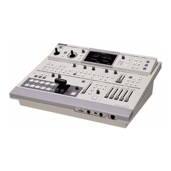
- Page 1 Operating Instructions Production Mixer WJ-MX50 Panasonic Before attempting to connect or operate this product, please read these instructions completely...
- Page 2 We declare under our sole responsibility that the product to which this declaration relates is in conformity with the standards or other normative documents following provisions Directives EEC/73/23 and EEC/89/336 i————__ _. _ _ - _ — _ - — — — F o r Australia—————i THIS APPARATUS MUST BE EARTHED.
-
Page 3: Table Of Contents
WJ MX50 and your imagination there are many possible In addition to the Mix Effect of the conventional Production function combinations which are left to your creativity Mixer, the WJ-MX50 includes such features as Chroma Key and Luminance Key functions Additionally this unit has... -
Page 4: Precautions
PRECAUTIONS The WJ-MX50 is a sensitive, high quality instrument and should be treated with care. And because it is an electrical device, the danger of electric shock exists if it is used inappropriately. x Do not attempt to disassemble the instrument. In order •... -
Page 5: Major Operating Controls And Their Functions
2. When the Editing Controller AG-A800 is used with Chroma Level Control (8). WJ-MX50, the power of AG-A800 should be off first to turn off the power of WJ-MX50. The power 7. Colour - A Button (A) of WJ-MX50 can not be turned off by-itself. - Page 6 9. Audio Level Indicator (AUDIO LEVEL) 17. Effect - Out Button (EFFECT) This Indicator indicates the audio output level of the When this button is pressed, the final video signal - Program Out 1 Audio Output Connector (135) and the whether it is effected or not will be provided at the Program Out 2 Audio Output Jacks (134) Program Output connector.
- Page 7 •TOP VIEW 2 30. Aspect ON/OFF Button (ON) 25. Border Button (BORDER) In case the Aspect (unction is required, this button must This button is used for selecting a border wipe edge. Pressing this button once selects a narrow border. first be pressed.
- Page 8 Mono, Paint,Still or Strobe) can be synchronized to after another repeatedly by pressing this button. pulse with certain levels of accompanying music or sound supplied to the WJ-MX50. 55. Once Only Button (ONCE) Each of the multiple video images will be scanned one 44.
- Page 9 Note: 68. Corner Wipe Button The difference between on and off of this button The video scene is wiped with a square shape from the corner of the monitor screen Four kinds of patterns are available. Output Signal Resolution FRAME BUTTON 2-field Standard 69.
- Page 10 •TOP VIEW 3 72. NAM Select Button (NAM) 76. Chroma Key Select Button (CHROMA KEY) NAM (Non Additive Mix) effect is obtained by pressing The Chroma Key effect is obtained by pressing this this button and the Mix/Wipe Lever (99) is to be button and the adjustment of the Hue Control (77) and positioned at centre The darker area on the B-bus...
- Page 11 94. B-bus Fade Button (B) 81. Matte Fade Button (MATTE) The video fade signal is faded out to the B-bus video The video fade signal is faded out to the selected Matte signal by pressing this button. Colour by pressing this button. 95.
-
Page 12: Front View
•FRONT VIEW 107. Title Input Connector (TITLE) 103. Headphone Level Control (LEVEL) This connector is used to connect the optional The audio level of the headphone can be adjusted with Character Generator WJ-KB50 (recommended) this control. The pin numbers are stated below. 104. - Page 13 115. Source 3 COMP Input Connector 108. Demo ON/OFF Switch (DEMO ON/OFF) (SOURCE3/COMP) When this switch in the ON position, This connector accepts a 1 0 Vp-p/75 ohms composite preprogrammed mixer features demonstration takes video signal. place. 116 Source 3 Y/C Input Connector (SOURCE4-Y/C) 109.
- Page 14 123. Program Out-1 COMP Output Connector 134. Program Out-2 Audio Output Jacks (PROGRAM OUT 1/COMP) (PROGRAM OUT 2/AUDIO, L/R) The Program Output Signal-1 of the composite video The audio output signals of R channel and L-channel signal is provided via this connector. on the Program Output 2 are provided via these jacks.
-
Page 15: System Connection
SYSTEM CONNECTION For the details of operations, setting up of controls and This system diagram shows the example of Panasonic A/B connections for the VTR's, refer to the corresponding ROLL EDITING SYSTEM with 2 Playback VTRs, 1 Recording VTR and 1 Editing Controller AG-A800... - Page 16 Note The ADV REF, ADV SYNC or BLACK BURST signal should be used. The enough editing accuracy may not be obtained without this signal. This signal is necessary for the Compression function and Trail function when it is recorded on the VTR - 15 -...
- Page 17 Input Conector (141) /Source 2 Audio Input Connector (140)/Program Out-1 Audio Output Connector (135) on the WJ MX50 and the AUDIO OUT connector/AUDIO connector PlaybackVTR-1/Playback VTR-2/Recording VTR respectively. (3) Set the Source Selection Switch (114) on the WJ-MX50 to the S1-2 position. Connect control cables between...
-
Page 18: Operation
AC power cord. Call service personnel before attempting further use. 3. The power of WJ-MX50 can be turned on from the Stand-by mode by turning on the power of AG-A800. In this case the LED of the Mix Select Button (73) turns on instead of the Wipe Select Button (74). -
Page 19: B Basic Operation
Note: B. Basic Operation-1 The A bus or B bus video signal sent out from the PROGRAM OUT connecctors (123) (126) will be B-1. Input/Output Selection effected by the Colour Correction, Digital Effect, Position, Downstream Key, Mix Effect and Fade Source Selector Control So do not add these effects to the video The audio/video signal to be inputted for effect is... - Page 20 B-4. Colour Correction B-3. Audio Mixer This function allows for the adjustment of colour from There are 7 audio source inputs on the WJ-MX50 - the selected input source, as well as compensation the Source 1/2/3/4, 2 auxiliary audio inputs (AUX1, 2) for excessive colour Using the monochrome effect, a and the external microphone.
-
Page 21: C Basic Operation 2 Digital Effect Bloc
C. Basic Operation-2 B-5. Position Control The position of the specific wipe pattern can be Digital Effect block changed on the monitor screen using Position Control The following instructions detail the Digital Effect block function function which generates digital special effects for the A-bus and B-bus source video signals In order to add the desired effect(s) on the A-bus (B-bus) signal, press the... - Page 22 Monochrome Press the MONO Button (34). A black and white image can be obtained. 4. Paint Press the PAINT Button (36). An oil-paint touch image can be obtained. The graduation level of the simulated paint can be changed continuously by adjusting corresponding LEVEL Control (35).
-
Page 23: D Basic Operation-3 Mix And Wipe Block
3. The A/V Synchro mode can not be used together with the Trail mode. A/V Synchro Press the A/V SYNCHRO Button (43). The music or sound supplied to the WJ-MX50 can trigger other D-1. Mix selected Digital Effect(s) except the Trail mode. • Press the MIX Button (73) •... - Page 24 Notes: • Operate the Mix/Wipe Lever (99) from A-bus to B-bus, 1. The wipe pattern can be generated in combination or vice versa to the desired display ratio. with the Wipe Pattern Select Buttons and the • The Mix/Wipe LED's (100) will light as appropriate. Modify Buttons.
- Page 25 • Press the REVERSE Button (28) The movement of the wiped scene will be executed in the reverse direction • Press the COMPRESSION Button (71) once compressed video scene (fully displayed but at available size) is wiped in/out on the monitor screen •...
- Page 26 • Press the PAIRING Button (65). A paired wipe scene • Press the SLIDE Button (69) twice. The A-bus and can be obtained. B-bus images will slide in/out over each other. • The PAIRING Button (65) can be used in combination (3) Multi with the MULTI Button (67).
- Page 27 (5) Split Wipe Pattern (2) Corner Wipe Pattern • Press the Split Wipe Button (62). The following patterns • Press the Corner Wipe Button (68). The following can be selected by pressing this button repeatedly. patterns can be selected by pressing this button repeatedly.
- Page 28 • If the wipe pattern number of 99 is accessed by the AG A800, the wipe pattern which is currently set up by the WJ-MX50 will be generated. • The round in the Pattern Table means that the wipe pattern is available but neither access from the external Editing Controller nor the wipe pattern indication is possible.
- Page 29 WIPE PATTERN TABLE Wipe Pattern Selection Buttons Modify PATTERN Button MODE No Modify Button COMPRESSION I (Single-Bus) COMPRESSION II (A-B-Bus) SLIDE I (Single Bus) SLIDE I I (A-B-Bus) PAIRING BLINDS MULTI MODE 1 MULTI MODE 2 MULTI MODE 3 MULTI MODE 4 -28 -...
- Page 30 - 2 9 -...
- Page 31 Wipe pattern Selection Buttons Modify PATTERN Button MODE | MULTI MODE 5 MULTI MODE 6 MULTI MODE 1 & PAIRING MULTI MODE 2 8. PAIRING MULTI MODE 3 & PAIRING MULTI MODE 4 & PAIRING MULTI MODE 5 & PAIRING MULTI MODE 6 &...
- Page 32 Remarks Each box number should be read as, 001 ——> Normal Wipe 129 ——> Reverse Wipe The box marked (O) can be accessed by external controller. However, the wipe pattern can be available No wipe pattern is available for the blank box - 3 1 -...
-
Page 33: Downstream Key
Basic Operation-4 In case the title is written with black letters on the white card, adjust the High Level Key Control (54) to obtain a clear Downstream Key edge key image. The following instructions detail the Downstream Key block. This function is mainly used for superimposing the characters or letters as for a telopper. -
Page 34: F Basic Operation 5 Fade
F. Basic Operation-5 Note : If the automatic fading is to be operated, first Fade adjust the TRANSITION Control (91) to the desired auto fading time. Then press the AUTO FADE Synchronized fading makes it possible to operate the Button (92) when ready to execute. The Auto-Fade Video, Downstream Key and Audio fades together, or in can be stopped during Auto-fading by pressing this any combination. -
Page 35: G Basic Operation-6 Audio Follow
G. Basic operation-6 Notes : 1. If the automatic fading is to be operated, first Audio Follow adjust the TRANSITION Control (91) to the desired Audio can be processed either separately or in conjunction auto fading time. Then press the AUTO FADE' Button (92) when ready to execute. -
Page 36: H Application
H. Application H-1. Event Memory Functions H-2. Special Mode Functions Customized effect combinations can be stored in Under ' Special Mode eight factory preset effect the Event Memory, and later recalled tor subsequent functions are accessible for use. These demonstrate a access. - Page 37 • The memorized program can be recalled and performed Note : one after another by pressing the AUTO TAKE Button When the Square Wipe Button (60) is selected (97) repeatedly at this moment, the Mode 6 changes to the The Auto-Take can be stopped during Auto-taking by Circle Wipe mode.
- Page 38 • The Positioner Joystick (2) now controls the location of the mosaic image. • If the border is desired to highlight the "anonymous" area, press the BORDER Button (25) on the WIPE PATTERN block. • If the Reverse function (REVERSE Button (28)) and/or the Monochrome function (MONO Button (34)) is added, more highlight effect can be produced.
-
Page 39: Interface
DSK OUT INTERFACE DSK IN The WJ-MX50 is equipped with the interface capability for Event Memory No.1 use with an external remote controller such as the AG-A800 (Editing Controller), a personal computer or a GPI function product. Refer to the service personnel or system installer No.1... - Page 40 RS422 2. Refer to the table below for transmitting protocol The optional Editing Controller AG-A800 can be used between the RS232C DT/WJ-MX50 connection. with the WJ-MX50 to control it remotely in the VTR SW701 Editing System. Switch Name Description Setting up...
-
Page 41: Specifications
SPECIFICATIONS X 4 (SOURCE 1/2/3/4) Source Input 1 0 Vp-p/75 Ohms, PAL signal, BNC x4 Composite Video Input. Y signal, 1 0 Vp-p/75 Ohms, C signal, 03 Vp-p/75 Ohms, S-Video Input Mini DIN 4 connector X 4 SOURCE 1/2, XLR type x 2, +4 dBm/600 ohms (Balanced), Left and Right Audio Input: SOURCE 3/4, Pin-jack x 2, -6 dBs/20 Kohms (Unbalanced), Left and Right. - Page 42 WIPE PATTERNS (EDITING CONTROLLER RS-42. MULTI MULTI COMPRESSION SLIDE PAIRING BASIC BLINDS WIPE NO. PAIRING PATTERNS SINGLE SINGLE MULTI MULTI A/B COMP. A/B SLIDE MODE NO. MODE NC NOR. REV. REV. REV. REV. REV. NOR.; REV. NOR. REV. NOR.; RE\ NOR.
Need help?
Do you have a question about the WJ-MX50 and is the answer not in the manual?
Questions and answers