Table of Contents
Advertisement
TABLE OF CONTENTS
1 Safety Precautions----------------------------------------------- 2
2 Specifications ----------------------------------------------------- 3
3 Location of Controls and Components ------------------- 4
3.1. Parts Identification----------------------------------------- 4
3.2. How to Use-------------------------------------------------- 6
3.3. How to Assemble / Disassemble ---------------------- 8
3.4. Safety Lock/Circuit Breaker Protection--------------- 9
3.5. How to Use Plastic jar with Filter Unit ---------------10
3.6. How to Clean ----------------------------------------------12
4 Troubleshooting Guide ----------------------------------------14
5 Disassembly and Assembly Instructions ---------------17
5.1. Rubber Cap, Connector U (lower)--------------------17
5.2. Bottom Plate -----------------------------------------------17
5.3. Power Cord U / Circuit Breaker -----------------------18
5.4. Switch Complete------------------------------------------19
5.5. Switch Complete B ---------------------------------------19
Model No.
Chassis
Product Color
Destination
PAGE
5.6. Motor Complete / Upper Body ------------------------ 20
5.8. Lid C (Lid A / Lid J) -------------------------------------- 24
6 Wiring Connection Diagram--------------------------------- 25
6.1. Schematic diagram -------------------------------------- 25
6.2. Wiring diagram-------------------------------------------- 26
7 Exploded View and Replacement Parts List ----------- 27
7.1. PARTS LOCATION -------------------------------------- 27
7.2. REPLACEMENT PARTS LIST ----------------------- 28
7.3. PACKING INSTRUCTION ----------------------------- 30
© Panasonic Corporation 2012 Unauthorized copy-
ing and distribution is a violation of law.
Order Number PHAI1210605CE
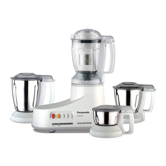
Mixer Grinder
MX-AC400WRA
Vietnam
PAGE
Advertisement
Table of Contents

Related Manuals for Panasonic MX-AC400WRA


Summary of Contents for Panasonic MX-AC400WRA
-
Page 1: Table Of Contents
5.1. Rubber Cap, Connector U (lower)--------------------17 5.2. Bottom Plate -----------------------------------------------17 5.3. Power Cord U / Circuit Breaker -----------------------18 5.4. Switch Complete------------------------------------------19 5.5. Switch Complete B ---------------------------------------19 © Panasonic Corporation 2012 Unauthorized copy- ing and distribution is a violation of law. -
Page 2: Safety Precautions
1 Safety Precautions... -
Page 3: Specifications
2 Specifications... -
Page 4: Location Of Controls And Components
3 Location of Controls and Components 3.1. Parts Identification... -
Page 6: How To Use
3.2. How to Use... -
Page 8: How To Assemble / Disassemble
3.3. How to Assemble / Disassemble... -
Page 9: Safety Lock/Circuit Breaker Protection
3.4. Safety Lock/Circuit Breaker Protection... -
Page 10: How To Use Plastic Jar With Filter Unit
3.5. How to Use Plastic jar with Filter Unit... -
Page 12: How To Clean
3.6. How to Clean... -
Page 14: Troubleshooting Guide
4 Troubleshooting Guide... -
Page 17: Disassembly And Assembly Instructions
5 Disassembly and Assembly Instructions For assembly, refer to the Assembly Instructions, and perform the procedures in the opposite order of disassembly. 5.1. Rubber Cap, Connector U (lower) 1. Remove Rubber Cap 2. Turn the Nut clockwise, and remove it. 3. -
Page 18: Power Cord U / Circuit Breaker
5.3. Power Cord U / Circuit Breaker 1. Remove the Screw (4x10) which fixes the Motor Com- Assembly Instructions Attach the Lead Wire to the Circuit Breaker, and set plete, and remove the Lead Wire (Yellow). Insulation Tubes firmly. 2. Move the 2 Insulation Tubes from the Circuit Breaker, 3. -
Page 19: Switch Complete
5.4. Switch Complete 1. Remove the faston terminal of Lead Wire A (U). 3. Remove the Screw (4x20), and remove the Switch Com- 2. Melt the solder and detach the Lead Wire Yellow, Blue, plete. Red from the Motor Complete. 5.5. -
Page 20: Motor Complete / Upper Body
5.6. Motor Complete / Upper Body 1. Remove the 2 Screws (4x20) 2. Put the body upside-down and remove the Upper Body. 3. Remove the 4 Special Tapping Screws, which fix the Motor Complete, and remove the Motor Complete. Assembly Instructions Add vaseline in 2 hole positions of Seal Cap before assembling into the upper body. -
Page 21: Blender Jar Complete (Pc Jar / Ss Jar) / Mill Cup Complete / Chutney Jar Complete
5.7. Blender Jar Complete (PC Jar / SS Jar) / Mill Cup Complete / Chutney Jar Complete 1. Set the Spatula to the Cutter assemble, insert the long- nose pliers into the holes of the Connector Insert (upper), turn it as shown in the picture and take out the blade. 2. - Page 22 3. Remove 4 pcs of M4 nuts and the trust tapping screw fixing Handle to Jar(Cup) in order to disassemble Blender Jar assembly, Mill Cup assembly or Chutney Jar assembly.
- Page 23 Assembly Instructions a. Apply Silicone Adhesive Sealant(TSE382C) into the screw holes(4 portions) of Cutter Base (U). b. Cutter Base Packing B for PC Jar is to be set in the correct direction as shown in the figure. the grooves b are to be in alignment with the holes a of Cutter Base Cover.
-
Page 24: Lid C (Lid A / Lid J)
5.8. Lid C (Lid A / Lid J) 1. Remove Gasket C (Gasket A) from part "a" of Lid C / Lid J(Lid A). Assembly Instructions a. Pay attention to the orientation of Gasket C (Gasket A). Assemble it in the correct orientation. b. -
Page 25: Wiring Connection Diagram
6 Wiring Connection Diagram 6.1. Schematic diagram As shown in the wiring diagram heavy duty motor's yellow wire is connected with low speed switch terminal, blue wire is connected with medium speed switch terminal, red wire is connected with maximum speed switch terminal. Motor black wire is connected to power cord black wire, Power cord green wire is connected to motor body for earth and Red wire is connected to circuit breaker. -
Page 26: Wiring Diagram
6.2. Wiring diagram... -
Page 27: Exploded View And Replacement Parts List
7 Exploded View and Replacement Parts List 7.1. PARTS LOCATION... -
Page 28: Replacement Parts List
REPLACEMENT PARTS LIST Notes:Important safety notice • Components identified by mark have special characteristics important for safety. • " When replacing any of these components use only manufacturer's specified parts." MODEL No.MX-AC400WRA Pcs/Set Safety Ref. No. Part No. Part Name & Description... - Page 29 Pcs/Set Safety Ref. No. Part No. Part Name & Description Remarks AC400WRA AVE78-124-W0 Filter Unit AVE55-124 Filter Gasket AVA34-193 Blender Jar AVA37-124-W0 Handle Top Cover(S) AVA39-193-W0 Blender Handle(S) AVE52-193-W0 Blender Handle AVE48-193 Blender Interlock Rod AVE26-193 Cutter Base Cover AVE29-193 Cutter Base Packing B AVE01-193 Blender Jar...
-
Page 30: Packing Instruction
7.3. PACKING INSTRUCTION...
Need help?
Do you have a question about the MX-AC400WRA and is the answer not in the manual?
Questions and answers