Table of Contents
Advertisement
Quick Links
Download this manual
See also:
Technical Manual
Advertisement
Chapters
Table of Contents

Subscribe to Our Youtube Channel
Related Manuals for Tektronix PG 508


Summary of Contents for Tektronix PG 508
- Page 94 Nachfolgend ist das Service-Manual abgebildet, welches die US-Army für dieses Gerät herausgegeben hat. Möglicherweise sind hier zusätzliche Informationen verfügbar.
- Page 95 TM 11-6625-2980-14 TECHNICAL MANUAL OPERATOR'S, ORGANIZATIONAL, DIRECT SUPPORT AND GENERAL SUPPORT MAINTENANCE MANUAL PULSE GENERATOR AN/USM-359A (NSN 6625-01-077-4620) (TEKTRONIX MODEL PG 508 WITH TM 503) HEADQUARTERS, DEPARTMENT OF THE ARMY 27 MARCH 1981...
- Page 96 TM 11-6625-2980-14 SAFETY SUMMARY This manual contains safety information which the user must follow to ensure safe operation of this instrument. WARNING information is intended to protect the operator; CAUTION information is intended to protect the instrument. The following general safety precautions must be observed during all phases of operation, service, and repair of this instrument.
- Page 97 TM 11-6625-2980-14 This manual contains copyright material reproduced b)y permission of Tektronix. Inc. TECHNICAL MANUAL HEADQUARTERS DEPARTMENT OF THE ARMY No. 11-6625-2980-14 WASHINGTON, DC, 27 March 1981 OPERATOR'S, ORGANIZATIONAL, DIRECT SUPPORT, AND GENERAL SUPPORT MAINTENANCE MANUAL GENERATOR, PULSE AN/USM-359A (TEKTRONIX MODEL PG 508 WITH TM 503)
- Page 98 TM 11-6625-2980-14 TABLE OF CONTENTS Page Page Section 0 INTRODUCTION APPENDIX A TM 503 MAINFRAME Section I. INSTALLATION PROCEDURE SECTION 1 OPERATING INSTRUCTIONS Instrument Description Section II. TM 503 OPERATING INSTRUCTIONS Installation and Removal Introduction BASIC OPERATION Powering Up Period and Duration Selection Building a System Duty Factors Specifications...
- Page 99 PG 508 power supply schematic diagram. 4-21 burst operation.1-6 FO-12 TM 503 power supply schematic diagram. 4-23 Typical propagation delays using PG 508 with Al board component locations. DD 501 in counted burst mode at 50 MHz FO-13 A2 board component locations. repetition rate.
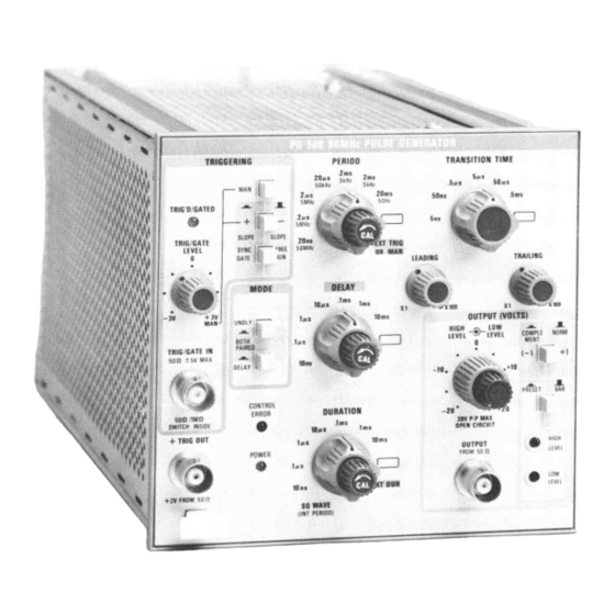
- Page 100 TM 11-6625-2980-14 Figure 1-0 . Pulse generator AN/USM-359A...
-
Page 101: Introduction
359A and provides instructions for operation and NA.VSUPI NST 4610.33B/AFR 75-18/MCO P4610.19C maintenance. Throughout this manual, and DLAR 4500.15. 1178/USM-359A is referred to as Tektronix Model PG 508 and PP-7578/USM 359A is referred to as TM 503. Reporting Equipment Improvement Recommendations (EIR) Indexes of Publications If your AN/USM-359A needs improvement, let us a. -
Page 102: Operating Instructions
PG 508. Check that the PG 508 is fully synchronous gate input with level and slope controls, inserted in the power module. Pull the power switch on square wave output and complementary pulse output for the power module. -
Page 103: Basic Operation
TM 11-6625-298014 or a 500pF capacitor. If a polarized capacitor is BASIC OPERATION used, observe the correct polarity. Use at least a 6 V rated capacitor. Connect this capacitor as shown in Fig. Period and Duration Selection 1-2. The period generator operates, in all modes except Duty Factors EXT TRIG or MAN, at a rate set by the PERIOD range switch and variable control. -
Page 104: Transition Time Selection
±30 V. when the PG 508 is operating into a 50 ( load. The For external gating select the desired period and OUTPUT (VOLTS) controls are interlocked to prevent duration. -
Page 105: Trigger Output
OPERATING CONSIDERATIONS Output Termination’s and Connections The PG 508 operates as a voltage source in series Control Settings Operation with an internal 50 n( impedance. Maximum pulse... -
Page 106: Connections
PRESET button (PRESET), place This application permits pre-selecting the number of the PERIOD switch in the EXT TRIG OR MAN position, output pulses from the PG 508. The event is initiated by DURATION NORM an externally applied signal or pulse, 5 ns or longer. The COMPLEMENT switch in the NORM position (out). -
Page 107: Location Of Trigger Jumpers In Dd 501 For
TM 11-6625-2980-14 Fig . 1-5 . Location of trigger jumpers In DD 501 for selecting trigger or delay Interval output . Fig . 1-6 . PG 508-DD 501 Interconnections for counted burnt operation . -
Page 108: Repetition Rate
COUNT setting. To determine the number of extra lights on the DD 501 and the TRIG'D/GATED light on pulses for a given PG 508 period, set the PG 508 and the PG 508 will be off until the DD 501 is triggered. -
Page 109: Definitions Of Pulse Characteristics
TM 11-6625-2980-14 Definitions of Pulse Characteristics The following Flatness. The absence of long term variations to is a glossary of common pulse characteristics used in the pulse top; excluding overshoot, ringing or pulse this manual. They are illustrated in Fig. 1-8. rounding. -
Page 110: Specifications
TM 11-6625-2980-14 Pulse Duration. The time interval between the Risetime. The time interval, at the step function leading and trailing edge of a pulse at which the leading edge, for the pulse to rise from the 10% to 90% instantaneous amplitude reaches 50% of the peak pulse amplitude levels. - Page 111 TM 11-6625-2980-14 Source Off: (Logic False) TRIG/GATE IN input potential below TRIG/GATE LEVEL with + SLOPE Impedance: 50 .Ω selected above TRIG/GATE LEVEL with - SLOPE selected. Duty Cycle: Internal Trig- Synchronous Gate: Rate generator starts gering -50%. synchronously with external gating signal and completes the last output pulse.
-
Page 112: Environmental Requirements
TM 11-6625-2980-14 Environmental Requirements. following extended, lifting the front panel for ease in reading or adjusting controls. However, under difficult operating paragraphs describe environmental operating conditions for the pulse generator. conditions (such as limited space), the pulse generator may be used in other positions without impairment of the electrical characteristics, including setting the The pulse generator can be operated where the cabinet on the four protective bumpers on the rear... -
Page 113: Using The Rear Interface Connectors
Use the connections to make socket on the board Install a twelve inch cable with the custom inputs or outputs to the PG 508 through the proper connectors, Tektronix Part No 175-1827-00, from Power Module... - Page 114 Assignments listed for pin 1A - 13A and 1B - 13B are available in all power modules; however only those pins marked with an asterisk (*) are used by the PG 508. Those connections marked with a double asterisk (**) are the only connections used on the E board.
-
Page 115: Theory Of Operation
+5 V is applied to pin 4 of U70A. This gate is PG 508. now inhibited and the signal passes through U70C. As the outputs of U70A and C are connected together, a Input Circuitry high on either output overrides the low. -
Page 116: Period Generator
TM 11-6625-2980-14 Period Generator generator with about a 10 ns trigger pulse under all input This circuitry generates the internal period timing conditions The positive-going trigger pulse, at pin 5 of U300A, waveform. In this mode, U140B operates as an a stable causes pin 3 to go low and pin 2 high. -
Page 117: Light Circuitry
TM 11-6625-2980-14 12 goes high during the pulse duration time and if pin 13 linear rate until the diode CR600 turns on. This diode is low, pin 15 goes high and pin 14 low. Pin 13 controls serves as the negative clamp. The voltage at the anode U400C in the square wave and external duration modes. -
Page 118: Simplified Schematic For Control Error Indicator Logic With Control Settings Causing Illumination
TM 11-6625-2980-14 Fig . 2-1 . Simplified schematic for CONTROL ERROR Indicator logic with control settings causing Illumination . proximately the same amount as the circuitry in the flip flop U720B (waveform driving the transition time variable transition time generator. The positive-going board) goes positive (end of pulse), the high on D input, waveform from pin 14 of U740C is fed through pin 6 to pin 10, transfers to the output, pin 15, and the... -
Page 119: Level Control Multiplier
TM 11-6625-2980-14 pulse is slow enough so that the D input of flip flop Both control voltages range U720A has not reached the high level when the pulse at between 0 and +5.2 V. When the control voltages are the clock terminal (pin 6) of flip flop U720A goes high equal, the Y input is zero and the multiplier signal output (leading portion of the next pulse driving the transition (X.Y) equals zero. -
Page 120: Output Amplifier
TM 11-6625-2980-14 variations and dc offset currents are summed at the tracking supply is +6 to +26 V, with a -6 to -26 V range collectors of Q945 and 0954, the output pulse high level for the negative supply. changes to maximum voltage and the low level remains at OV. - Page 121 TM 11-6625-2980-14 to the mainframe transistor used as the series pass the positive direction, the collector of 01255 goes element, until the inverting and non-inverting inputs are negative This increases current flow through Q1280 and approximately equal. At this condition, the series pass therefore the series pass transistor in the mainframe transistor drops the voltage from the raw supply until the which raises the + tracking supply voltage to the output...
-
Page 122: Service Information
The overline on a signal name indicates that the signal performs its intended function when it goes to the low state. Abbreviations are based on ANSI Y1.1-1972. Other ANSI standards that are used in the preparation of diagrams by Tektronix, Inc. are: Y14.15, 1966 Drafting Practices. -
Page 123: Adjustments
General first remove the four screws on the plug-in rear panel Adjustments for the PG 508 are described below. For and remove the panel. Next remove the TRANSITION complete calibration procedures, refer to TB 11-6625 TIME knob. -
Page 124: Replaceable Mechanical Parts List
TM 11-6625-298014 Section 5-PG 508 REPLACEABLE MECHANICAL PARTS PARTS ORDERING INFORMATION Attaching Parts always appear in the same indentation the item it mounts, while the detail parts are indented to the right. higher For complete part information, refer to TM 11-6625-2980-24P. Indented items are part of, and included with, the next... - Page 125 PARTS LOCATION GRID GRID GRID GRID GRID R102 R104 R106 R110 P110 R112 P1248 R113 C104 P1251 R1250 C106 P1253 C110 C1246 C1248 TP36 C1250 025 B2 CR16 030 B2 CR17 Q100 CR25 0102 CR26 Q110 VR20 CR82 VR22 CR84 VR65 CR86 CR1246 C1...
- Page 126 TM 11-6625-2980-14 FO-16 Index 1 2 3 4 5 Name & Description SHIELD,ELEC: SIDE COVER,PLUG-IN:TOP AND BOTTOM (ATTACHING PARTS) SCREW,MACHINE:6-32 X 0.188 INCH,PNH STL - - - * - - - KNOB,LATCH: (ATTACHING PARTS) PIN,KNOB SECRG:0.094 OD X 0.120 INCH LONG - - - * - - - KNOB:GRAY •...
- Page 127 TM 11-6625-2980-14 FO-16 Index Qty 1 2 3 4 5 Name & Description BASE,LAMPHOLDER:0.29 OD X 0.19 CASE LAMPHOLDER:WHITE PLASTIC WASHER,FLAT:0.265 ID X 0.375 OD INCH AL LAMP,LED: (DS110 AND DS1250) EPL LAMP,LED: (DS500 ) SHIELD,ELEC:REAR SUBPANEL CKT BOARD ASSY:AUXILLARY(A5) •...
- Page 128 TM 11-6625-2980-14 FO-16 Index Qty 1 2 3 4 5 Name & Description • • ACTUATOR ASSEMBLY INCLUDES: • • CONTACT,ELEC:GROUNDING • • NUT,PLAIN,HEX.:4-40 X 0.188-INCH,BRS • • SPRING,FLAT:GREEN COLORED • • SPRING,FLAT:RED COLORED • • ROLLER,DETENT: • • BEARING,CAM SW:FRONT (ATTACHING PARTS) •...
- Page 129 TM 11-6825-2980-14 FO-16 Index Qty 1 2 3 4 5 Name & Description • • ACTR ASSY INCLUDES: -129 • • COVER,CAM SW:1.85 L X 0.876 H,AL (ATTACHING PARTS) -130 • • SCREW,MACHINE:4-40 X 0.25 INCH,PNH STL -131 • • WASHER,LOCK:INTL,0.12 ID X 0.26"OD,STL - - - * - - - •...
- Page 130 TM 11-6625-2980-14 FO-16 Index Qty 1 2 3 4 5 Name & Description -165 • • NUT,PLAIN,HEX.:4-40 X 0.188 INCH,BRS -166 • • BEARING,CAM SW:CENTER/REAR -167 • CKT BOARD ASSY:TIMING( A2) -168 • • SWITCH,PUSH:(S380A,8) -169 • • SWITCH,PUSH:(S380A,B,C) -170 •...
-
Page 131: Installation Procedure
TM 11-6625-2980-14 APPENDIX A Section I. INSTALLATION PROCEDURE Before you start... 1. Check the rear panel markings. If the factory settings are compatible with the available line voltage and frequency, insert the desired plug-ins. Use the bail to raise the front of the instrument..go to Operating Instructions... - Page 132 TM 11-6625-2980-14 b. Line Range Taps Universal Transformer Line Regulating Ranges Selector Block Position 120 Volts Nominal 220-Volts Nominal 90 VAC to 110 VAC 180 VAC to 220 VAC 99 VAC to 121 AC 198 VAC to 242 VAC 108 VAC to 132 VAC 216 VAC to 264 VAC Line Fuse Data...
-
Page 133: Tm 503 Operating Instructions
Section II. INTRODUCTION Description Power Usage The TEKTRONIX TM 503 Power Module is a three- With three plug-in modules installed, the TM 503 compartment-wide mainframe for the TM 500 Series of can require up to 120 W of power at the upper limits of Modular Instrumentation. - Page 134 TM 11-6625-2980-14 voltage range settings. Actual power consumed, of course, depends on the particular module combination In external loads, and (3) operating in an ambient selected at any one time. temperature around +250C. This power capability can best be utilized by The TM 503 provides each plug-in module with access carefully planning the functional combinations of plug- to a pair of heat-sinked, chassis-mounted transistors,...
-
Page 135: Building A System
Family Compatibility compatibility with the customized wiring. Mechanically, the plug-in modules are very similar to other TEKTRONIX product families. However, they are not electrically compatible. Therefore, the TM 503 interface has barriers on the mating connectors between Rear Panel pins 6 and 7 to insure that incompatible plug-ins cannot be inserted. -
Page 136: Specifications
TM 11-6625-2980-14 SPECIFICATIONS Power Requirements +33.5 V and -33.5 V, 1 A maximum each supply, shared by all compartments. Line Voltage Ranges. Universal Transformer: 100, 17.5 VAC and +11.5 V, 3.6 A maximum, shared in 110, 20, 200, 220, 240 VAC, all within 10%. Range any combination between these two supplies and shared changing or transformer accomplished with quick-... -
Page 137: Tm 503 System Maintenance
TM 11-6625-2980-14 TM 503 SYSTEM MAINTENANCE Section III. GENERAL used; however, abrasive cleaners should not be used. Introduction This section of the manual is meant to support the entire TM 500 Series family of modules with a general coverage of the most commonly-needed service information pertinent preventive... -
Page 138: Troubleshooting Aids
TM 11-6625-298014 TROUBLESHOOTING AIDS Introduction Circuit Board Illustrations The following is provided to augment information Line illustrations showing component locations contained elsewhere in this and other TM 500 Series keyed with a grid scheme for each circuit board are family manuals when troubleshooting... - Page 139 TM 11-6625-2980-14 known to be operating properly. If the trouble persists most components can be lifted at one end from the after substitution, then the power module is probably at circuit board. fault. Moving a properly operating plug-in from Transistors and IC's. Turn the power switch off compartment to compartment will help determine if one before removing or replacing any semiconductor.
-
Page 140: Parts Replacement
TM 11-6625-2980-14 PARTS REPLACEMENT Replacing edges. For these, push the mounting clips away from the circuit board edges to free the board. Also, remove any knobs, etc., that would prevent the board from being The exploded view drawings associated with the lifted out of the instrument. - Page 141 TM 11-6625-2980-14 Replacement semiconductors should be of the avoid damaging the pins. Pull slowly and evenly on both original type or a direct replacement. The above figure ends of the IC. Try to avoid having one end of the IC shows the lead configuration of the semiconductors disengage from the socket before the other end.
- Page 142 TM 11-6625-2980-14 Interconnecting Pins. To replace a pin which is 3. Remove the screws (from the opposite side of mounted on a circuit board, first disconnect any pin the circuit board) which hold the cam drum to the board. connectors. Then, unsolder the damaged pin and pull it out of the board with a pair of pliers.
- Page 143 TM 11-6625-2980-14 Power Transformer. Refer to the exploded view 2. Surround the instrument with polyethylene sheeting to protect the finish of the instrument. drawing at the rear of the Power Module manuals for disassembly of the rear panel to expose the power transformer.
-
Page 144: Diagrams And Circuit Board Illustrations
The overline on a signal name indicates that the signal performs its intended function when it goes to the low state. Abbreviations are based on ANSI Y1.1-1972. Other ANSI standards that are used in the preparation of diagrams by Tektronix, Inc. are: Y14.15, 1966 Drafting Practices. -
Page 145: Power Module Interface Pin Assignments
TM 11-6625-2980-14 POWER MODULE INTERFACE PIN ASSIGNMENTS FRONT VIEW A-15... -
Page 146: Detailed Block Diagram
TM 11-6625-298014 DETAILED BLOCK DIAGRAM A-16... -
Page 147: Replaceable Mechanical Parts
TM 11-6625-2980-14 REPLACEABLE MECHANICAL PARTS SPECIAL NOTES AND SYMBOLS X000 Part first added at this serial number Attaching Parts always appear in the same Part removed after this serial number indentation as the item it mounts, while the detail parts are indented to the right. - Page 148 TM 11-6625-2980-14 Index 1 2 3 4 5 Name & Description COVER,CAL FXTR:W/HANDLE (ATTACHING PARTS) SCREW,MACHINE:6-32 X 0.188 INCH,PNH STL SCREW,MIACHINE:8-32 X 0.188,TRH,SST - - - * - - - • COVER INCLUDES: • COVER,CAL FXTR:W/O HANDLE • HANDLE,CARRYING: (ATTACHING PARTS) •...
- Page 149 TM 11-6625-2980-14 Index Qty 1 2 3 4 5 Name & Description LINK,TERM. CONN:8,22 AWG,1.5 L LINK,TERM. CONN:8,22 AWG,1.5 L • BRACKET,REIF·F: (ATTACHING PARTS) • DELETED • RIVET,BLIND:0.125 DIA GRIP,AL - - - * - - - (ATTACHING PARTS FOR CKT BD ASSY) SCREW,MACHINE:6-32 X 0.375 INCH,PNH STL NUT,CHASSIS MTG: NUT,PLAIN,EXT W:6-32 X 0.312 INCH,STL...
- Page 150 TM 11-6625-2980-14 Index Qty 1 2 3 4 5 Name & Description • CABINET BOTTOM ASSEMBLY INCLUDES: • CAB.BOT,PWR SUP: • FOOT,CABINET:LEFT FRONT AND RIGHT REAR • SPT PIVOT,FLIP:LEFT FRONT AND RIGHT REAR (ATTACHING PARTS FOR EACH) • SCREW,IMACHINE:6-32 X 0.75 INCH,FILH STL •...
- Page 151 TM 11-6625-2980-14 STANDARD ACCESSORIES Index 1 2 3 4 5 Nome & Description BUMPER,PLASTIC:0.45 DIA X 0.195 GRAY POLY MANUAL, TECH: INSTRUCTION TM 503 POWER MODULE A-25/(A-26 blank)
-
Page 152: Appendix B References
TM 11-6625-298-14 APPENDIX B REFERENCES DA Pam 310-4 Index of Technical Publications: Technical Manuals, Technical Bulletins, Supply Manuals (Types 7, 8, and 9), Supply Bulletins, and Lubrications Orders. DA Pam 310-7 US Army Index of Modification Work Orders. SB 38-100 Preservation, Packaging, Packing and Marking Materials, Supplies, and Equipment Used by the Army. -
Page 153: Introduction
TM 11-6625-2980-14 APPENDIX C COMPONENTS OF END ITEM AND BASIC ISSUE ITEMS LISTS Section I. INTRODUCTION B-1. SCOPE TOE/MTOE authorization of the end item. This appendix lists components of end item and basic issue items for the pulse generator to help you inventory B-3. -
Page 154: Components Of End Item
TM 11-6625-2980-14 Pulse generator AN/USM-395A. SECTION II. COMPONENTS OF END ITEM Illus National Stock Description Usable Number Number FSCM and Part Number On Code PANEL, BLANK: (80009) 016-0195-03 6625-01-051-6639 PLUG-IN UNIT, ELECTRONIC TEST EQUIPMENT. SG-1178/USM-359A (80009) PG-508 6625-00-373-7528 POWER SUPPLY. PP-7578/USM-359A (80009) TM-503 TM 11-6625-2980-14... -
Page 155: Basic Issue Items
SECTION III. BASIC ISSUE ITEMS Illus National Stock Description Usable Number Number FSCM and Part Number On Code MANUAL, TECHNICAL: TM 11-6625-2980-14 C-3/(C-4 blank) -
Page 156: Appendix E Maintenance Allocation
TM 11-6625-2980-14 APPENDIX E MAINTENANCE ALLOCATION Section I. INTRODUCTION E-1. General Consists of comparisons of two instruments, one of which is a certified standard of known accuracy, to detect and adjust any discrepancy in the accuracy of the This appendix provides a summary of the maintenance operations for the Pulse Generator AN/USM-359A. -
Page 157: Column Entries
TM 11-6625-2980-14 E-3. Column Entries (Section II) Column 5, Tools and Equipment. Column 5 specifies by code, those common tool sets (not Column 1.Group Number. Column 1 lists individual tools) and special tools, test, and support equipment required to perform the designated function. group numbers, the purpose of which is to identify components, assemblies, subassemblies, and modules with the next higher assembly. - Page 158 TM 11-6625-2980-14 SECTION II. MAINTENANCE ALLOCATION CHART PULSE GENERATOR AN/USM-359A TEKTRONIX PG-508T NSN 6625-01-077-4620 MAINTENANCE LEVEL UNIT UNIT INTERMEDIATE INTERMEDIATE DEPOT DEPOT GROUP MAINTENANCE TOOLS AND NUMBER COMPONENT ASSEMBLY FUNCTION EQUIPMENT REMARKS PULSE GENERATOR AN/USM-359A Inspect Visual External Simple Operational...
-
Page 159: Remarks
TM 11-6625-2980-14 SECTION II. MAINTENANCE ALLOCATION CHART PULSE GENERATOR AN/USM-359A TEKTRONIX PG-508T NSN 6625-01-077-4620 MAINTENANCE LEVEL UNIT UNIT INTERMEDIATE INTERMEDIATE DEPOT DEPOT GROUP MAINTENANCE TOOLS AND NUMBER COMPONENT ASSEMBLY FUNCTION EQUIPMENT REMARKS 0201 CIRCUIT CARD ASSY (Al) Inspect 670-2024-00 Test... -
Page 160: Tool And Test Equipment Requirements For Pulse Generator An/Usm-359A
NOMENCLATURE NATIONAL/NATO NUMBER REF CODE STOCK NUMBER Oscilloscope, 0S-262 (P)/U, Equivalent to TEKTRONIX 6625-01.007-9416 Type 7623A Amplifier, Dual Trace AM-6785/U, equivalent to TEKTRONIX 6625-00-361-5318 Type 7A26 Time Base, TD-1159/U, equivalent to TEKTRONIX 6625-00-261-5139 Type 7B53A Digital Delay 7Dll 6625-00-506-1132 Generator, Square-Wave, equivalent to TEKTRONIX... -
Page 161: Appendix F Expendable Supplies And Materials List Introduction
TM 11-6625-2980-14 APPENDIX F EXPENDABLE SUPPLIES AND MATERIALS LIST Section I. INTRODUCTION F-1. SCOPE This appendix lists expendable supplies and materials you will need to operate and maintain the pulse generator. These items are authorized to you by CTA 50-970, Expendable Items (Except Medical, Class V, Repair Parts, and Heraldic Items). -
Page 162: Expendable Supplies And Materials
TM 11-6625-2980-14 SECTION II. EXPENDABLE SUPPLIES AND MATERIALS NATIONAL ITEM STOCK NUMBER LEVEL NUMBER DESCRIPTION 8020-00-721-9657 Brush, paint 7920-00-862-6710 Cloth, lint-free Paint Sandpaper Detergent 6850-00-105-3084 Trichlorotrifluoroethane *U.S. GOVERNMENT PRINTING OFFICE: 1981- 703-029: 1049 By Order of the Secretary of the Army:... - Page 163 E. C. MEYER General, United States Army Official: Chief of Staff J. C. PENNINGTON Major General, United States Army The Adjutant General DISTRIBUTION: To be distributed in accordance with DA Form 12-34B, Requirements for TMDE/Calbr & Repair.
- Page 164 TM 11-6625-2980-14 Section 4-PG 508 CONTROLS AND CONNECTORS FO-1. Controls and connectors 4-1/(4-2 blank)
- Page 165 TM 11-6625-2980-14 FO-2. Block Diagram 4-3/(4-4 blank)
- Page 166 TM 11-6625-2980-14 FO-3. Input circuit schematic diagram. 4-5/(4-6 blank)
- Page 167 TM 11-6625-2980-14 FO-4. Period generator schematic diagram 4-7/(4-8 blank)
- Page 168 TM 11-6625-2980-14 FO-5. Delay generator schematic diagram. 4-9/(4-10 blank)
- Page 169 TM 11-6625-2980-14 FO-6. Duration generator and control error circuit schematic diagram. 4-11/(4/12 blank)
- Page 170 TM 11-6625-2980-14 FO 7. Transition time generator schematic diagram 4-13/(4-14 blank)
- Page 171 TM 11-6625-2980-14 FO -8. Level control multiplier schematic diagram. 4-15/(4-16 blank)
- Page 172 TM 11-6625-2980-14 FO -9. Output amplifier schematic diagram. 4-17/(4-18 blank)
- Page 173 TM 11-6625-2980-14 FO-10. Tracking voltage supply schematic diagram 4-19/(4-20 blank...
- Page 174 TM 11-6625-2980-14 FO-11. PG 508 power supply schematic diagram. 4-21/(4-22 blank)
- Page 175 TM 11-6625-2980-14 FO-12. TM 503 power supply schematic diagram. 4-23/(4-24 blank)
- Page 176 TM 11-6625-2980-14 FO-13. A2 board component locations. 5-3/(5-4 blank)
- Page 177 TM 11-6625-2980-14 FO-14. A3 board component locations. 5-5/(5-6 blank)
- Page 178 TM 11-6625-2980-14 FO-15. A4 board component locations. 5-7/(5-8 blank)
- Page 179 TM 11-6625-2980-14 FO-16. PG 508 exploded view. 5-9/(5-10 blank)
- Page 180 TM 11-6625-2980-14 A-17/(A-18 blank)
- Page 181 TM 11-6625-2980-14 TM 503 POWER MODULE A-23/(A-24 blank)
Need help?
Do you have a question about the PG 508 and is the answer not in the manual?
Questions and answers