Table of Contents
Advertisement
Quick Links
I NSTRUCTION
MANUAL
109
TYPE
PULSE GENERATOR
-------------------------------------------
S 'A ' -
, f ' / 7 ----------
Tektronix, Inc.
S.W . M illikan W a y
•
P. O . Box 500
•
Beaverton, O rego n
•
Phone Ml 4-0161
•
C ab le s: Tektronix
Tektronix International A .G .
Terrassenw eg 1A
•
Z u g , Sw itzerland
•
P H .0 4 2 -4 9 1 9 2
•
C a b le : Tekintag, Zu g Sw itzerland
•
Telex 53.57 4
563
0 7 0 -2 9 9
Advertisement
Chapters
Table of Contents

Related Manuals for Tektronix TYPE 109


Summary of Contents for Tektronix TYPE 109
- Page 1 P. O . Box 500 • Beaverton, O rego n • Phone Ml 4-0161 • C ab le s: Tektronix Tektronix International A .G . Terrassenw eg 1A • Z u g , Sw itzerland • P H .0 4 2 -4 9 1 9 2 •...
-
Page 2: Warranty
A ll Tektronix instruments are w arranted against defective m aterials and w o rkm an ship for one y e a r. Tektronix transform ers, m anufactured in our own p lan t, are w a r ranted for the life of the instrument. -
Page 3: Table Of Contents
CONTENTS W a rra n ty Section 1 C haracteristics Section 2 O perating Instructions Section 3 A pplications Section 4 Circuit Description Section 5 M aintenance Section 6 C alib ration Section 7 Parts List and Diagram... - Page 4 { RISETIME < 0,25 NA NOSEC ) EXT. POWER OR MONITOR 5 G / V CHG. U N S EXT. PWR. PULSE POLARITY - ' T H * f lU R N OFF IO EXTEND M ERCURY SWITCH UFE Type 109...
-
Page 5: Characteristics
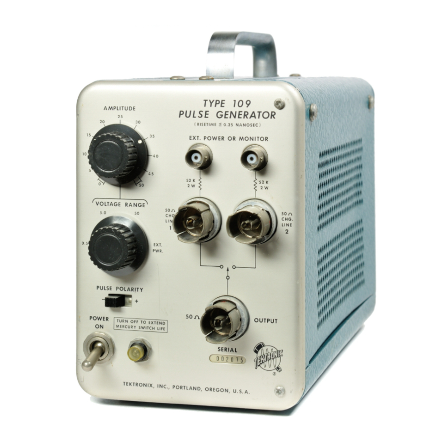
The Tektronix Type 109 Pulse Generator is a fast-risetime pulse generator similar to the pulse generator section of the Type 110. The Type 109 is capable of producing pulses of different widths, calibrated-amplitudes, and polarities for use in driving and testing the response of devices operating in the nanosecond region. - Page 6 Unequal charge lines produce alternate pulses of differ g ro u n ds unused connector. ent time durations but of the same amplitude and polarity using the Type 109 internal power supply as shown in Fig. 1-7. Repetition Rate External charge...
- Page 7 Textured- aluminum cabinet with vinyl-based blue finish. Dimensions— 7 % " high, 5” wide, and 11’A ” deep overall. Net Weight— 8 lbs. 7 ounces (Type 109 only). Accessories 1— Power Cord, (161-010). V e rtic a l D e flectio n F a c to r: 9 .5 v/cm...
- Page 8 NOTES...
-
Page 9: Operating Instructions
As soon the rear of the instrument indicates the nominal line voltage as the POWER O N switch is turned on, the Type 109 is for which the Type 109 was wired at the factory. If wired ready to operate. - Page 10 The upright position is the normal operating position contact point. for the Type 109. If the instrument is placed on its side The transit time of the cable is defined as the time or turned upside down, the mercury in the mercury switch...
- Page 11 An additional advantage in using external power to charge the coaxial lines is that alternate pulses of differ Included with your Type 109 is a special Charge Network ent amplitudes and/or polarity can be generated by using designed to produce a fast-rise pulse that decays one RC two different power sources.
- Page 12 NOTES...
-
Page 13: Applications
Some fundamental factors to consider when preparing the falling portion of the waveform. Type 109 Pulse Generator for use with other equipment Pulse Width (or Duration) tw: the time duration of the will be covered in this section of the manual. Several repre... - Page 14 Do not allow more than 200 pieces such as coax cables is a variable depending upon volts dc to be applied to the Type 109 Pulse Generator 500 the cable characteristics as well as individual risetimes. The OUTPUT connector.
- Page 15 Type 109 is applied to the of the 125-ohm cable used is actually 5 nsec.
- Page 16 Type 109. If devices such as these are used, they will prevent the charge line from charging to where: Z = the unknown impedance.
- Page 17 (If the last factor is a prohibitive limit, then a Tektronix Direct Connection to Deflection Plates Sampling Oscilloscope should be considered as another way...
- Page 18 After removing the wire lead, measure the total capaci are listed in Table 3-1. tance between the plates with a Tektronix Type 130 LC As a specific example, showing before and after results, Meter, or equivalent, at the deflection plate pins. Capaci...
- Page 19 Type 109 was applied to the Type K high-quality cable, some rolloff occurred and components Unit to show how the pulse rise and fall times are limited C3 and R5 had to be added to sharpen the leading corner by the bandwidth of the vertical amplifier.
- Page 20 Applications— Type 109 Open end. F ig . 3 - 1 0 . A p p ly in g the T yp e 1 0 9 p u lse thro ugh d efle ctio n p la te connector n e tw o rk to the crt v e rtic a l d e fle ctio n p la te s .
- Page 21 Applications— Type 109 O p e n en d . T Y P E 5 4 0 -S E R IE S O S C IL L O S C O P E C H A R G E LIN E 1 0 X PR O B E ©...
- Page 22 NOTES...
-
Page 23: Circuit Description
R612 and Zener D612 for regulation. The voltage drop AC power for the Type 109 is applied through a recepta across the Zener is nominally 10 volts. This 10-volt drop is cle on the rear of the unit to the primary windings of T601. - Page 24 Circuit Description— Type 109 control R614 and a resistor R615. The FREQUENCY control of Q725 and Q735, decreases the ripple and spike ampli sets the voltage applied to the base of Q613. Transistor tudes at the emitter of Q627, and improves the 10-volt power supply regulation at low-line voltage.
-
Page 25: Waveform Moni
Circuit Description— Type 109 SIMPLIFIED CHARGE CIRCUIT (Using separate charge lines.) CHARGE LINE 1 WAVEFORM MONI TORED AT THE CHG. LINE 1 CONNECTOR CHARGE LINE 2 WAVEFORM MONI TORED AT THE CH G. LINE 2 CONNECTOR ALTERNATE PULSE WAVEFORMS AT THE 50 ß... -
Page 26: Connector
Circuit Description— Type 109 Dip due to capacitive Dip due to capacitive coupling of backwave coupling of backwave CHARGE LINE WAVEFORM AT CHG. LINE 1 AND 2 CONNECTORS WAVEFORM AT OUTPUT CONNECTOR Reed closes Contact Reed closes Contact Reed closes Contact... - Page 27 50 Q CH G . LINE 2 connector (see Fig. 4-4). The to twice the setting of the VO LTAG E RANGE switch. The operation of the Type 109 is the same as before except pulse amplitude control network is designed to provide a...
- Page 28 NOTES...
-
Page 29: Maintenance
Tektronix Field Office either unwired or Calibration with all parts and wire straps soldered in place, as desired. The Type 109 should provide many hours of trouble-free Refer to the Parts List for the part number to use. operation. - Page 30 Standard Parts If you frequently perform work on Tektronix instruments, it Replacements for all parts used in the Type 109 can be is advisable that you have a stock of solder containing purchased through your Tektronix Field Office, at current about 3% silver.
- Page 31 -|-10-Volt Power Supply; Table 5-3 is a troubleshooting guide for checking the ± 1 05-Volt Power Supply. Front-Panel Controls When a trouble occurs in the Type 109, you should first Checking Semiconductors recheck the settings of all controls to see that they are set properly.
- Page 32 Maintenance— Type 109 (T ) < D -< ■ g n" < < <Q (/ > ■ o_ < D ■ o...
- Page 33 Maintenance— Type 109 <n < > 1...
- Page 34 NOTES...
-
Page 35: Calibration
Type 109 Pulse Generator is provided in this section of the manual. Apparent troubles in the instrument are occasionally the result of an improper adjustment. Consequently, calibration checks should be an integral part of any troubleshooting procedure. - Page 36 + 17V 18Q, 30Q + or — 105 and 125 volts (or 210 and 250 volts if Type 109 is wired to operate in this range). Minimum rating of 0.070 * Fig. 6-3 shows the physical locations of these test points.
- Page 37 Calibration— Type 109 3. Check Frequency Range and Amplitude a. Set the front-panel controls on the conventional test Collector oscilloscope to the following settings: Q725 Input coupling Volts/Cm 1 Volt Calibrated Variable Volts/Cm Preset Stability Triggering Mode Triggering Slope Time/Cm...
- Page 38 210 and 250) volts and check the waveform for the control following characteristics: a. Set the Type 109 VO LTAG E RANGE switch to EXT. (1) Check for a clean, steady waveform display similar PWR. to the one shown in Fig. 6-6a. The closure inter...
- Page 39 + 10 V test point (see Fig. 6~3) to the con nector end of R752 (see Fig. 6-7) and turn on the Type 109. Disconnect the mercury switch tester leads and the Check waveform amplitude and duration. Then, repeat the 1 0 X probe from the Type 109.
- Page 40 Connect a 5-nsec cable between the 50 Q OUTPUT the Type 109.) connector on the Type 109 and Input A on the sam Power pling oscilloscope. A Position Midrange d.
- Page 41 If a part you have ordered has been replaced with a new or improved part, your local Tektronix Field Office will contact you concerning any change in part number. ABBREVIATIONS AND SYMBOLS...
- Page 42 Parts List— Type 109 FRONT REF. S E R IA L N O . P A R T N O . N O . EFF. D IS C . D E S C R IP T IO N 333-658 PANEL, front...
- Page 43 Parts List— Type 109 REAR S E R IA L N O . R E F . P A R T N O . N O . EFF. D IS C . D E S C R IP T IO N...
- Page 44 Parts List— Type 109 RIGHT SIDE...
- Page 45 Parts List— Type 109 RIGHT SIDE R EF. S E R IA L N O . D E S C R IP T IO N N O . P A R T N O . EFF. D IS C .
- Page 46 Parts List — Type 109 LEFT SIDE...
- Page 47 Parts List— Type 109 LEFT SIDE R E F . S E R I A L /M O D E L N O . N O . P A R T N O . EFF. D IS C . D E S C R IP T IO N...
- Page 48 Parts List— Type 109 CABINET...
- Page 49 Parts List— Type 109 ACCESSORIES R E F . S E R IA L N O . P A R T N O . EFF. D E S C R IP T IO N N O . D IS C .
- Page 51 Parts List— Type 109 PARTS LIST Values are fixed unless marked Variable. Bulbs Tektronix Ckt. No. Part Number Description S/N Range B601 150-019 Neon, Type NE-2E Pilot Light Capacitors Tolerance ± 2 0 % unless otherwise indicated. Tolerance of all electrolytic capacitors are as follows (with exceptions): 3 V —...
- Page 52 Parts List— Type 109 Resistors (continued] Tektronix Ckt. No. Part Number Description S/N Range R679 306-152 1.5 k R690 311-071 2.25 k 110-V SET R691 309-036 y 2 w Prec. R692 309-020 1.8 meg ’A w Prec. R694 309-153 20 k y 2 w Prec.
- Page 53 MANUAL CHANGE INFORMATION At Tektronix, we co ntin ually strive to keep up with latest electronic developm ents by adding circuit and component improvements to our instruments as soon as they are developed and tested. Sometimes, due to printing and shipping require...
- Page 55 TYPE 109 PARTS LIST CORRECTION CHANGE TO: Mercury Switch, Checked *260-0282-02 M9UL1/L65...
- Page 56 " i “ i " i...
Need help?
Do you have a question about the TYPE 109 and is the answer not in the manual?
Questions and answers