Table of Contents
Advertisement
Quick Links
Download this manual
See also:
User Manual
Advertisement
Table of Contents

Related Manuals for Barco R9050100


Summary of Contents for Barco R9050100
- Page 1 CLM R10+ Users manual R9050100 R90501001 R59770021/06 07/07/2008...
- Page 2 Barco nv Events Noordlaan 5, B-8520 Kuurne Phone: +32 56.36.89.70 Fax: +32 56.36.88.24 E-mail: sales.events@barco.com Visit us at the web: www.barco.com Printed in Belgium...
-
Page 3: Software License Agreement
The period of guarantee begins on the date of transfer of risks, in the case of special systems and software on the date of commissioning, at latest 30 days after the transfer of risks. In the event of justified notice of complaint, Barco can repair the fault or provide a replacement at its own discretion within an appropriate period. - Page 4 OF THE PRODUCT OR REFUND OF PURCHASE PRICE. GNU-GPL code If you would like a copy of the GPL source code contained in this product shipped to you on CD, please contact Barco. The cost of preparing and mailing a CD will be charged.
-
Page 5: Table Of Contents
Table of contents TABLE OF CONTENTS 1. Safety ....................... .. 5 General . - Page 6 Table of contents 8.2.2 Input configuration ......................62 Input locking .
- Page 7 Table of contents 12.10 White peaking ........................123 12.11 ScenergiX .
- Page 8 Table of contents A. Dimensions ......................177 Dimensions of the CLM R10+ .
-
Page 9: Safety
• Before operating this equipment please read this manual thoroughly, and retain it for future reference. • Installation and preliminary adjustments should be performed by qualified Barco personnel or by authorized Barco service deal- ers. • All warnings on the projector and in the documentation manuals should be adhered to. - Page 10 Caution: High pressure lamp may explode if improperly handled. Refer servicing to qualified service personnel. The customer should never attempt to disassemble the lamp casing or to dispose of the lamp casing other than by returning it to Barco. •...
- Page 11 flammable or combustible materials are present. The exclusion zone must be not less than 40 cm (16”) for all Barco DLP projectors. The exclusion zone on the lens side must be at least 2 meter (80”).
-
Page 12: Recycling Guidelines
If the product exhibits a distinct change in performance, indicating a need for service. • Replacement parts: When replacement parts are required, be sure the service technician has used original Barco replacement parts or authorized replacement parts which have the same characteristics as the Barco original part. Unauthorized substitu- tions may result in degraded performance and reliability, fire, electric shock or other hazards. -
Page 13: Important Warnings Concerning Clm Flight Cases
1. Safety Important warnings concerning CLM flight cases Important warnings concerning stacking/transporting CLM rental flight cases • Stack maximum two (2) CLM rental flight cases high. Never higher. • Surface on which flight case is standing must be level to ensure that the total load is evenly spread out among the four wheels. The surface must also be able to support the load safely. - Page 14 1. Safety R59770021 CLM R10+ 07/07/2008...
-
Page 15: General
Projector weight Do not underestimate the weight of one Barco CLM R10+, which is about ±31 kg (±68 lb.). Be sure that the table or truss installation on which the projector(s) has to be installed is capable of handling five (5) times the complete load of the complete system. -
Page 16: Unpacking The Projector
2. General Which screen type ? There are two major categories of screens used for projection equipment. Those used for front projected images and those for rear projection applications. Screens are rated by how much light they reflect (or transmit in the case of rear projection systems) given a determined amount of light projected toward them. -
Page 17: Box Content
This check should confirm that there are no broken knobs or connectors, that the cabinet and panel surfaces are free of dents and scratches, and that the operating panel are not scratched of cracked. The Barco sales and service office should be notified as soon as possible. -
Page 18: Projector Configurations
2. General Projector configurations The different configurations Depending on the installation the projector can be mounted in different ways, the 4 different configurations are: Front / Table (F/T) Front / Ceiling (F/C) Rear / Table (R/T) Rear / Ceiling (R/C) For a ceiling mounted configuration, the optional carry handle kit is required. -
Page 19: Positioning The Projector
2. General Positioning the projector SCREEN FLOOR Image 2-5 On-Axis / Off-Axis projection The position of the projector with reference to the screen may also be different depending on the installation. Basically the projector can be positioned in On-Axis or Off-Axis configuration. On-Axis configuration means that the projector is positioned so as to have the centre of the lens coinciding with the centre of the screen. - Page 20 Side to side tilt must not exceed 10°. This limit ensures that the lamp in the projector operates properly and safely. Front - back tilting is limited to 10°. When using the projector out of this range, Barco cannot guarantee a safe operation and the responsibility is for the installer/operator.
-
Page 21: Projector Air Inlets And Outlets
Projector Toolset is only available in a download version, no CD can be ordered. Where to find the download file(s) The program and all necessary plug-ins, as well as the Reference manual can be downloaded for free from Barco’s Partnerzone, (URL: www.partnerzone.events.barco.com). Registration is necessary. - Page 22 2. General R59770021 CLM R10+ 07/07/2008...
-
Page 23: Physical Installation
3. Physical installation 3. PHYSICAL INSTALLATION About this chapter This chapter explains how to install and set up your CLM projector. If you are familiar with the projector and want to quickly set it up for temporary use, follow the “Quick setup” instructions below. For a more complete setup, follow the instructions and guides covered in the remaining subsections. -
Page 24: Rcu Battery Installation
3. Physical installation Overview • RCU battery installation • RCU rugged case installation • RCU XLR adaptor installation • Using the XLR adaptor of the RCU • RCU usage possibilities 3.1.1 RCU battery installation Where to find the batteries for the remote control ? The batteries are not placed in the remote control unit to avoid control operation in its package, resulting in a shorter battery life time. -
Page 25: Rcu Rugged Case Installation
3. Physical installation 3.1.2 RCU rugged case installation Only with optional rugged case kit which is part of the touring kit (R9861000). Necessary tools No tools. Necessary parts Touring kit How to install the rugged case of the remote control ? 1. -
Page 26: Using The Xlr Adaptor Of The Rcu
3. Physical installation Image 3-6 Mounting the XLR adapter 2. Fasten the two screws (S) of the XLR adaptor. Turn each screw repeatedly one or two turns until both screws are tight. 3.1.4 Using the XLR adaptor of the RCU How to use the XLR adaptor of the remote control unit ? 1. -
Page 27: Lenses
3. Physical installation Image 3-8 Lenses Overview • Available lenses • Lens selection • Lens formulas • Lens formulas 3.2.1 Available lenses Overview First series lenses: Image 3-9 Image 3-10 Image 3-11 R9849870: CLD zoom lens (1.2 - 1.6 : 1) R9861100: CLD zoom lens (1.6 - 2.4 : 1) R9849890: CLD zoom lens (2.4–4.3 : 1) Second generation lenses (no picture available yet) :... -
Page 28: Lens Selection
3. Physical installation Image 3-12 Image 3-13 Image 3-14 R9861060: CLD zoom lens (1.2–1.5 : 1) R9861070: CLD zoom lens (1.5–2.2 : 1) R9861080: CLD zoom lens (2.2–4.4 : 1) Image 3-15 R98610890: CLD zoom lens (4.4–7.0 : 1) Lens Order number CLD 1.2 - 1.5 R9861060... -
Page 29: Lens Formulas
3. Physical installation Image 3-16 PD for lens selection 3.2.3 Lens formulas Formulas Lens Throw ratio for Metric formulas (meter) Inch formulas (inch) CLD (1.2 - 1.6 : 1) 1.2 - 1.6 =1.216 x SW - 0.05 =1.216 x SW - 1.97 =1.657 x SW - 0.097 =1.657 x SW - 3.80 CLD (1.6 - 2.4 : 1) -
Page 30: Alignment Of A Table Mounted Clm Projector
3. Physical installation Alignment of a table mounted CLM projector How to align a table mounted CLM projector 1. Place the projector in the desired location. Take into account the zoom range of the used lens and the size of the screen. 2. - Page 31 3. Physical installation Image 3-19 Rigging slots and clamps Necessary tools Open end spanner 17 mm Necessary parts • Four rigging clamps (R855943) • Safety cable (B361213) • Two snap hook locks (B361212) Mounting the rigging points into the handle 1.
- Page 32 3. Physical installation X mm Image 3-21 4. Slide the rigging points on there place in the slots, according the measured distance and secure this position by fastening the nut completely. Ensure that the rigging points are symmetrically lined up, so that the projector will hang in balance. If necessary move point B from a transversal position to a longitudinal position.
- Page 33 3. Physical installation Image 3-24 Opening clamps 7. Place the projector (upside down) under the truss installation and lower the truss until the support bars of the truss are nearby the rigging clamps on the projector. Image 3-25 Mounting to truss 8.
-
Page 34: Alignment Of A Ceiling Mounted Clm Projector
3. Physical installation Image 3-26 Security cable AUTION Always mount the safety cable when suspending the projector. Alignment of a ceiling mounted CLM projector Necessary tools Spanner 17 mm How to align a ceiling mounted CLM projector 1. Install the projector in the desired location. See "Suspension of the CLM projector with rigging clamps", page 26. Take into account the zoom range of the used lens and the size of the screen. - Page 35 3. Physical installation Skew Image 3-28 Skew adjustment R59770021 CLM R10+ 07/07/2008...
- Page 36 3. Physical installation R59770021 CLM R10+ 07/07/2008...
-
Page 37: Stacking Clm Projectors
4. Stacking CLM projectors 4. STACKING CLM PROJECTORS Stacking of CLM projectors is only possible with optional touring kit. See "Mounting optional Carry handle", page 195 for more information. Overview • Stacking CLM projectors • Aligning stacked CLM projectors Stacking CLM projectors Preparations Install first a carry handle on the upper projector. - Page 38 4. Stacking CLM projectors Image 4-2 Close the interlocking 3. Are these projectors stacked for a ceiling mounted configuration? If yes, mount a safety cable from one side of the projector around the truss installation to the other side of the projector. Repeat this for the second projector.
-
Page 39: Aligning Stacked Clm Projectors
4. Stacking CLM projectors Image 4-4 Open the interlocking ARNING Never open an interlocking adapter of a stacked projector which is still suspended. First place the stacked projectors on the floor. Aligning stacked CLM projectors How to align two stacked CLM projectors 1. - Page 40 4. Stacking CLM projectors Inclination Image 4-6 Inclination adjustment 5. If necessary, adjust the skew of the stacked projector with respect to the reference projector by turning the screw on the right front side. Adjust until the outline of the hatch pattern is most symmetric with the reference hatch pattern. Skew Image 4-7 Skew adjustment...
-
Page 41: Connections
5. Connections 5. CONNECTIONS About this chapter This chapter describes more in detail the power (P), the input source (S) and the communication (C) connections of the CLM R10+. Image 5-1 Overview • Power connection • Input source connections • Communication connections Power connection AUTION... - Page 42 5. Connections Image 5-2 Power input 4. Connect the male side of the power cord to the local power net. Caution: Ensure that the power net meets the power requirements of the projector, which are: 100-120/200-240V 12/8A 50/60Hz. ARNING Do not attempt operation if the AC supply and cord are not within the specified voltage and power range.
-
Page 43: Input Source Connections
5. Connections 4 lamps on max. 3 lamps on Light output % Input voltage V Image 5-3 Input source connections General The input and communication unit is equipped with two input slots, which accept any type of input designed for the CLM projector. The modularity of the input modules makes the CLM projector very flexible regarding input source connectivity. -
Page 44: Communication Connections
5. Connections Image 5-8 Cover plate for unused input slot (R848607). HDCP DVI input (R9854465) (image not available) The CLM R10+ is standard equipped with one 5 cable input module and one DVI input module. Communication connections Communication interface DIAGNOSTIC CODE IR RECEIVER STBY / ON WARNING IR... -
Page 45: Projector Status
5. Connections RS232/422 output port RS232/422 input port XLR input port for remote control IR receiver M Two digit 7-segment display for diagnostic code Projector status The projector “status” LED (A) lights up green while in operation. The same LED lights up red when the projector is switched to standby. - Page 46 5. Connections RS232/422 input port RS232/422 output port Pin Description Pin Description GND : Ground GND : Ground DSR : Data Set Ready [RS232] DSR : Data Set Ready [RS232] RXD+ : Received Data [RS422] RXD+ : Received Data [RS422] —...
-
Page 47: Usb Port
5. Connections 10/100 Base-T — RJ45 port Pin Description RXD- — — USB port The communication interface is equipped with a master USB port, type “A” connector (H). This USB port will simplify the service procedures for software updates or for taking backup files from the projector without network connection. An USB-stick is plugged into the USB port and files can be transferred from or to the projector using the local or remote control unit. - Page 48 5. Connections R59770021 CLM R10+ 07/07/2008...
-
Page 49: Getting Started
6. Getting started 6. GETTING STARTED About this chapter This chapter describes the functions on the remote control and local keypad and gives an overview how to start up the projector. It gives also a brief overview of the direct adjustment possible with these controls. Overview •... - Page 50 6. Getting started MENU EXIT ENT ER PAUSE LENS TEXT EXIT MENU PHASE SHARP N PATTERN WINDOW LENS TINT ENTER RIGGING STBY PAUSE TEXT AUTO COLOR BRI GHTN CONTR LENS LENS ZOOM SHIFT LENS LENS SHIFT FOCUS Image 6-1 Local keypad & remote control Ind.
-
Page 51: Operating The Projector
6. Getting started Ind. Key name Description FREEZ To freeze the actual projected image. TEXT Toggle key to activate or deactivate on screen text boxes while adjusting a setting. When adjusting one of the image controls, e.g.during a meeting, the normally displayed bar scale can be deactivated by pressing ’TEXT’... -
Page 52: Errors, Warnings And Messages During Start Up
6. Getting started MENU EXIT ENTER PAUSE LENS TEXT EXIT MENU PHASE SHARPN TINT PATTERN WINDOW LENS COLOR ENTER RIGGING STBY PAUSE TEXT AUTO BRIGHTN CONTR LENS LENS ZOOM SHIFT LENS LENS SHIFT FOCUS Image 6-3 Stand by indication Stand by indication on local keypad Stand by indication on remote control The projector status LED lights up. -
Page 53: Switching Off
6. Getting started All custom settings are written to the internal backup device. A message ’Save data ...’ indicates this process. Never switch off the projector while this message is displayed. 6.3.4 Switching off How to switch off the projector? 1. -
Page 54: Quick Setup Adjustments
6. Getting started 45° 45° 45° 45° 45° 45° Image 6-5 RCU to one of the IR sensors Quick setup adjustments Overview • Text boxes ON or OFF • Quick Lens Adjustment • Quick picture in picture • Quick language selection 6.5.1 Text boxes ON or OFF Text toggle function... -
Page 55: Direct Lens Adjustment (Rcu)
6. Getting started 3. When finished, press EXIT key to return or ENTER to continue to the shift adjustment. Press the LENS key to switch to another pattern. Different patterns are available. Quick shift adjustment 1. Press the LENS key on the remote control or local keypad. The zoom/focus menu will be displayed. -
Page 56: Quick Picture In Picture
6. Getting started Horizontal shift 2. Press LENS FOCUS button [-] or [+] (C) for an overall focus of the image. 3. Press ▲ LENS SHIFT ▼ button for correct vertical position of the image on the screen. 4. Press ◄ LENS SHIFT ► button for correct horizontal position of the image on the screen. 6.5.3 Quick picture in picture Quick On - Off... -
Page 57: Use Of The Auto Button
6. Getting started Use of the AUTO button What is possible? The AUTO button can be configured as an auto align of the projected source or as an auto image button which calls a choice menu. Within this choice menu, the user can execute an auto align of the image, an auto contrast/brightness and an auto phase. To use this button, just press Auto on the remote control or the local key path. -
Page 58: Controlling The Projector
6. Getting started The LED on the remote control must lit up while pressing a digit key. Otherwise the address is not entered in the remote control. 6.7.2 Controlling the projector Projector address Address installed in the projector to be individually controlled. Common address Projector will always execute the command coming from a RCU programmed with that common address. -
Page 59: Controlling The Projector
6. Getting started Once the desired window is activated (main window or picture in picture window) all keys on the remote control or local keypad can now control that selected window. To select the source for the picture in picture window, press Window button until PiP window is activated and then select the desired source with the digit keys. - Page 60 6. Getting started R59770021 CLM R10+ 07/07/2008...
-
Page 61: Start Up Of The Adjustment Mode
7. Start up of the Adjustment mode 7. START UP OF THE ADJUSTMENT MODE Overview • About the adjustment mode • About the use of the remote control and the local keypad • Start up the adjustment mode • Navigation and adjustments •... -
Page 62: Navigation And Adjustments
7. Start up of the Adjustment mode The main menu of the adjustment mode opens. Image 7-1 Navigation and adjustments How to navigate in the menu structure? Once in the menu structure, use the ▲ or ▼ keys on the remote control (or the ▲ or ▼ (+ or -) key on the local keypad) to scroll through the items in the displayed menu. - Page 63 7. Start up of the Adjustment mode When quitting the menu structure, the backlighting of the LCD panel is switched off after a few seconds. R59770021 CLM R10+ 07/07/2008...
- Page 64 7. Start up of the Adjustment mode R59770021 CLM R10+ 07/07/2008...
-
Page 65: Input Menu
8. Input menu 8. INPUT MENU Overview • Overview flow • Slot module type • Input locking • Minimum delay • Native resolution • Source switching • No signal Overview flow Overview Level 1 Level 2 Level 3 Input 5-cable Slot module type HD-SDI - SDI DVI HDCP... -
Page 66: Input Configuration
8. Input menu AUTION Always install a cover plate on an unused input slot. This to prevent dust intrusion into the pro- jector. 8.2.2 Input configuration How to change? 1. Press MENU to activate the menus. 2. Use the ▲ or ▼ key to select Input and press ENTER. The Input menu is displayed. -
Page 67: Input Locking
8. Input menu Input Indication Description module RGB CV RGB input with composite video as sync signal RGB SOG RGB input with sync on green YUV HS/VS - CS Component video with separate horizontal and vertical sync or separate composite sync. - Page 68 8. Input menu Image 8-8 Image 8-7 Image 8-6 When: Free run Output is locked on an internal sync (60 Hz) Automatic Output is locked on the selected input for the main window Input 1 Output is locked on source 1 Input 2 Output is locked on source 2 The options menu changes depending on the selection.
-
Page 69: Minimum Delay
8. Input menu Genlock off (default position) locking done on input source of main window, when automatic was selected or on the selected input source when a specific input was selected. Projector detects automatically the vertical frequency and clock frequency of the input signal. A slightly difference with the source is possible. Genlock on locking done on indicated vertical frequency and clock frequency. - Page 70 8. Input menu Image 8-13 When the show native resolution function is in the ON position, the projector handles the source as follows: Source Projected image Name Ratio Resolution Ratio Resolution 1024x768 1024x768 image projected with black borders SXGA 1280x1024 1280x1024 image projected with black borders...
-
Page 71: Source Switching
8. Input menu Source switching Switching from one source to another To minimize undesired effects when switching from one source to another one can use the seamless switching mode, using the fade effect. Image 8-16 Example of fade effect Switching mode set up 1. -
Page 72: Shutdown Setting
8. Input menu 2. Use the ▲ or ▼ key to select Input and press ENTER. The Input menu is displayed. 3. Use the ▲ or ▼ key to select No signal and press ENTER to toggle between [Black] and [Blue]. Image 8-22 Image 8-21 Image 8-20... - Page 73 8. Input menu enter the desired value with the keyboard. When trying to exceed the maximum allowed value, the system will set it back to the maximum value. Image 8-28 Image 8-27 Image 8-26 R59770021 CLM R10+ 07/07/2008...
- Page 74 8. Input menu R59770021 CLM R10+ 07/07/2008...
-
Page 75: Image Menu
9. Image menu 9. IMAGE MENU Overview • Overview flow • How to select the image adjustments? • Image Settings • Aspect ratio • Timings • Image files services • Save custom settings Overview flow Overview Level 1 Level 2 Level 3 Level 4 Image... -
Page 76: How To Select The Image Adjustments
9. Image menu Level 1 Level 2 Level 3 Level 4 Vertical start Advanced settings Clamp delay Clamp width Field polarity Film mode detection Image file services Manual load Delete Delete all Rename Copy Options Load file Save custom settings How to select the image adjustments? Start up 1. -
Page 77: Contrast
9. Image menu 9.3.1 Contrast About Contrast The contrast function is used to adjust the contrast between the light and dark areas of the displayed image. How to change the contrast? 1. Press MENU to activate the menus. 2. Use the ▲ or ▼ key to select Image and press ENTER. 3. -
Page 78: Saturation
9. Image menu The higher the value, the higher the brightness. Image 9-8 Image 9-7 Image 9-9 Image 9-10 9.3.3 Saturation About (color) saturation The color function is used to adjust the color saturation levels. How to change the saturation? 1. -
Page 79: Tint (Hue)
9. Image menu 9.3.4 Tint (hue) About Tint The Tint function is used to adjust color hue to obtain true color reproduction and is only active for Video and S-Video when the NTSC color system is used. For PAL and SECAM sources, Tint is not accessible. How to change the saturation? 1. -
Page 80: Sharpness
9. Image menu How to change the phase? 1. Press MENU to activate the menus. 2. Use the ▲ or ▼ key to select Image and press ENTER. 3. Use the ▲ or ▼ key to select Image settings and press ENTER. 4. -
Page 81: Noise Reduction
9. Image menu Image 9-25 Image 9-24 Image 9-26 Image 9-27 9.3.7 Noise reduction About Noise reduction Reduces noise and pixel jitter in all video sources. How to change? 1. Press MENU to activate the menus. 2. Use the ▲ or ▼ key to select Image and press ENTER. 3. -
Page 82: Color Temperature
9. Image menu 9.3.8 Color temperature What can be done ? The color temperature can be selected according to the type of source: There are 5 different preset color temperatures: • Projector white • computer : 9300 K • Video : 6500 K •... -
Page 83: Set A Custom Color Temperature
9. Image menu Image 9-35 9.3.8.2 Set a custom color temperature How to enter a custom value? 1. Press MENU to activate the menus. 2. Use the ▲ or ▼ key to select Image and press ENTER. 3. Use the ▲ or ▼ key to select Image settings and press ENTER. 4. -
Page 84: Input Balance
9. Image menu 9.3.9 Input balance Overview • Introduction to Input Balance • Adjusting the input balance 9.3.9.1 Introduction to Input Balance Introduction: Unbalanced color signals When transporting signals, there is always a risk of deterioration of the information contained in the signals. In case of information contained in the amplitude of the signals which is the case of data color signals (R, G, B),image 9-41 , we are quite sure that the amplitude of these color signals is subject to alterations. -
Page 85: Adjusting The Input Balance
9. Image menu One can conclude here that a good data conversion can only be met by using three previously (input) balanced color signals The objective of input balancing The objective in input balancing is to “set” the same black level and the same white level for the three colors of a particular input source. -
Page 86: Black Balance
9. Image menu An alternative to a full screen White/black pattern is the standard gray scale pattern, the white bar will be used for white balance and the black bar for black balance. Image 9-45 Black balance 1. Press MENU to activate the menus. 2. -
Page 87: Aspect Ratio
9. Image menu If one uses a gray scale pattern, the bright spots should appear in the black bar. Performing White input balance 1. Connect the source you want to project. 2. Select a white pattern (or gray scale as alternative). 3. -
Page 88: How To Select An Aspect Ratio
9. Image menu Aspect ratio Description 16:9 Wide screen television format / anamorphic format Workstation format 2.35 Film format 1.88 1.78 Wide screen television format / anamorphic format Custom Any custom format can be set up Type of input signal is indicated above each image row. The image row shows how the image will be projected in the different aspect ratio settings. -
Page 89: Timings
9. Image menu Image 9-58 Image 9-59 Image 9-57 How to set up a custom aspect ratio? 1. Select first Custom and press ENTER to activate. The Custom aspect ratio dialog box opens. 2. Use the ▲ or ▼ key to adjust the vertical size of the image. Use the key to adjust the horizontal size of the image. -
Page 90: Advanced Settings
9. Image menu The timings menu will be displayed. Image 9-63 Image 9-62 Image 9-64 4. To change a setting, use the ▲ or ▼ key to select and press ENTER. The corresponding adjustment box is displayed. E.g. Horizontal total pixels. Image 9-65 5. - Page 91 9. Image menu How to change the clamp delay - clamp width? 1. Press MENU to activate the menus. 2. Use the ▲ or ▼ key to select Image and press ENTER. 3. Use the ▲ or ▼ key to select Timings and press ENTER. 4.
-
Page 92: Advanced Settings, Film Mode Detection
9. Image menu Image 9-72 Image 9-71 Image 9-73 Image 9-74 9.5.3 Advanced settings, film mode detection About film mode detection This mode detects whether film or video is displayed. When enabled, the hardware looks for tell-tale signs of 3:2 or 2:2 pull-down sequences. These are the result of converting cinema material recorded at 24 frames-per-second to the television frequencies of 60 or 50 interlaced fields per second respectively. -
Page 93: Advanced Setting, Brilliant Color Look
9. Image menu How to set up 1. Press MENU to activate the menus. 2. Use the ▲ or ▼ key to select Image and press ENTER. 3. Use the ▲ or ▼ key to select Advanced settings and press ENTER. The Advanced settings menu is displayed. -
Page 94: Image Files Services
9. Image menu Image 9-80 Image 9-79 Image 9-81 Image 9-82 Image files services Overview • Files and file manipulations • Manual Load file • Delete file • Delete all custom files • Rename a file • Copy a file •... -
Page 95: Manual Load File
9. Image menu 9.6.2 Manual Load file How to load? 1. Press MENU to activate the menus. 2. Use the ▲ or ▼ key to select Image and press ENTER. 3. Use the ▲ or ▼ key to select File services and press ENTER. The File service menu is displayed. -
Page 96: Delete All Custom Files
9. Image menu The delete window opens. 5. Use the ▲ or ▼ key to select the file which must be deleted. Note: Only custom files can be deleted. 6. Press ENTER to delete the selected file. Image 9-88 Image 9-89 Image 9-87 Image 9-90 No recovery possible ! -
Page 97: Rename A File
9. Image menu Image 9-92 Image 9-93 Image 9-91 Image 9-94 if you are not sure to delete all custom files, select No and press ENTER to activate the selection. 9.6.5 Rename a file How to rename? 1. Press MENU to activate the menus. 2. -
Page 98: Copy A File
9. Image menu Image 9-99 Image 9-98 9.6.6 Copy a file How to copy? 1. Press MENU to activate the menus. 2. Use the ▲ or ▼ key to select Image and press ENTER. 3. Use the ▲ or ▼ key to select File services and press ENTER. The File service menu is displayed. -
Page 99: Save Custom Settings
9. Image menu 2. Use the ▲ or ▼ key to select Image and press ENTER. 3. Use the ▲ or ▼ key to select Image services and press ENTER. The Image service menu is displayed. 4. Use the ▲ or ▼ key to select Options and press ENTER. Image 9-106 Image 9-107 Image 9-105... - Page 100 9. Image menu R59770021 CLM R10+ 07/07/2008...
-
Page 101: Layout Menu
10. Layout menu 10. LAYOUT MENU Overview • Overview flow • Main window • PIP window • Layout file services 10.1 Overview flow Overview Level 1 Level 2 Level 3 Level 4 Layout Main window Size Position PIP window PIP window [ON/OFF] Size Position Layout file services... -
Page 102: Size Adjustment
10. Layout menu The first character is highlighted. Use the ▲ or ▼ key to select the desired character and press key to select the next character in the name. Press EXIT to return. The new file is generated. 10.2.1 Size adjustment What can be done? The size of the main window can be adjusted until the desired window dimensions are reached. -
Page 103: How To Adjust Height And Width Separately
10. Layout menu 5. Toggle with ENTER till Lock is set to [x]. Image 10-7 [ ] = no lock between height and width. [x] = width and height are locked. 6. Use or▲ ▼ to adjust the size with respect to the original aspect ratio. When the desired size is reached, press EXIT. -
Page 104: Position Adjustment
10. Layout menu Image 10-12 [ ] = no lock between height and width. [x] = width and height are locked. 6. Use the ▲ or ▼ key to adjust the height. Use the ◄ or ► key to adjust the width. When the desired size is reached, press EXIT. -
Page 105: Pip Window
10. Layout menu Use the ◄ or ► key to adjust left start point. When the desired size is reached, press EXIT. A Save window opens. Image 10-17 Image 10-16 Image 10-15 Image 10-19 Image 10-18 6. Select with the ▲ or ▼ key Save and press ENTER. Select with the ▲... -
Page 106: Picture In Picture Activation
10. Layout menu Image 10-20 Position of PiP Top position Left position 10.3.2 Picture in Picture activation How to activate PIP? 1. Press MENU to activate the menus. 2. Use the ▲ or ▼ key to select Layout and press ENTER. 3. - Page 107 10. Layout menu Image 10-24 Size PIP window Width PIP window Height PIP window The size of the picture in picture window can be changed with respect to the original aspect ratio of the PIP image. Remark: when e.g. the PIP window is a 4 by 3 window and the projected image has a 16 by 9 format, then it is possible that image jumps inside the PIP window during a re-scaling.
-
Page 108: How To Change The Height And Width Separately
10. Layout menu Image 10-29 [ ] = no lock between height and width. [x] = width and height are locked. 6. Use the ▲ ▼ or ◄ ►key to adjust the size with respect to the aspect ratio. When the desired size is reached, press EXIT. A Save window opens. -
Page 109: Picture In Picture, Position Window
10. Layout menu Image 10-34 [ ] = no lock between height and width. [x] = width and height are locked. 6. Use the ▲ or ▼ key to adjust the height. Use the ◄ or ► key to adjust the width. When the desired size is reached, press EXIT. -
Page 110: Layout File Services
10. Layout menu Image 10-38 Image 10-37 Image 10-36 Image 10-40 Image 10-39 6. Select with the ▲ or ▼ key Yes and press ENTER. Select with the ▲ or ▼ key No, when no save is desired and press ENTER. 10.4 Layout file services Overview •... -
Page 111: Rename A Layout
10. Layout menu The load layout window opens. Image 10-43 Image 10-42 Image 10-41 Image 10-44 5. Use the ▲ or ▼ key to select the desired layout and press ENTER to select. The first 3 layouts are default layouts, all others are customer created layouts. The menu shows only the first 10 layouts, but use the ▼... -
Page 112: Delete A Layout
10. Layout menu Image 10-47 Image 10-46 Image 10-45 Image 10-48 10.4.3 Delete a layout What is possible? Custom created layouts can be removed from the projector memory. How to delete? 1. Press MENU to activate the menus. 2. Use the ▲ or ▼ key to select Window and press ENTER. 3. -
Page 113: Copy / Save As A Layout
10. Layout menu Image 10-52 The first 3 layouts are default layouts and cannot be delete. 5. Use the ▲ or ▼ key to select the layout that must be deleted. 6. Press ENTER to finalize the delete operation. 10.4.4 Copy / Save as a layout What is possible, An existing layout, system layout or custom created layout, can be copied into a new file. - Page 114 10. Layout menu Image 10-56 R59770021 CLM R10+ 07/07/2008...
-
Page 115: Lamp Menu
11. Lamp menu 11. LAMP MENU Overview • Overview flow • Lamp power mode • Lamp power • Lamp Identification • Status and run time overview lamps • Lamp mode 11.1 Overview flow Overview Level 1 Level 2 Level 3 Level 4 Lamp Power... -
Page 116: Lamp Power
11. Lamp menu How to switch? 1. Press MENU to activate the menus. 2. Use the ▲ or ▼ key to select Lamp and press ENTER. 3. Use the ▲ or ▼ key to select Power and press ENTER. 4. Use the ▲ or ▼ key to select Mode. 5. -
Page 117: Lamp Identification
11. Lamp menu Image 11-7 11.4 Lamp Identification About The lamp identification menu gives an overview of the most important parameters of the used lamps. It starts with the first lamp. Scrolling to other lamps is possible with the cursor keys. These parameters are: •... -
Page 118: Lamp Mode
11. Lamp menu The status and the run time for each lamp are displayed. Image 11-12 Image 11-13 Image 11-11 11.6 Lamp mode What can be done? The projector is equipped with 4 identical lamps. Depending on the main voltage, the lamp selection mode menu will show 4 lamps, 3 lamps, 2 lamps or a single lamp when starting up the projector. -
Page 119: Alignment Menu
12. Alignment menu 12. ALIGNMENT MENU About this chapter This chapter describes the alignment of the projector once the physical installation is finished. Via the software, the image will be perfectly aligned on the screen. Overview • Overview flow • Orientation •... -
Page 120: Orientation
12. Alignment menu Level 1 Level 2 Level 3 Full screen green Full screen red Full screen white Hatch Outline Color space Projector SMPTE Custom White peaking ScenergiX Status Bottom Left Right Show pattern Black level 12.2 Orientation What can be done? The way of physical installation of the projector can be defined to the projector. -
Page 121: Lens Adjustment
12. Alignment menu For more information about the physical installation, see chapter “General”, “Projector configurations”. 12.3 Lens adjustment Quick way to enter the lens adjustment setting; press the lens button on the local keypad or the remote control. Access to the lens adjustments 1. -
Page 122: Side Keystone
12. Alignment menu Image 12-10 Image 12-9 2. Use the ▲ or ▼ key to shift the lens upwards or downwards. Use the ◄ or ► key to shift the lens to the left or to the right. 12.4 Side keystone What can be done? The side keystone adjustment is used to align the image if the projector is mounted at a non standard projection angle. -
Page 123: Blanking
12. Alignment menu 12.5 Blanking What can be done ? Blanking adjustments affect only the edges of the projected image and are used to frame the projected image on to the screen and to hide or black out unwanted information (or noise). A ’0’ on the bar scale indicates no blanking. Which blanking adjustments are available ? •... -
Page 124: Intensity
12. Alignment menu Image 12-18 Image 12-16 Image 12-17 12.6 Intensity What can be done The light in the optical light path can be dimmed with a mechanical shutter plate. This way of light dimming will enhance the contrast of the image. Optical light dimming can reduce the light more than the lamp power reduction and it will enhance the contrast at the same time. -
Page 125: Internal Pattern
12. Alignment menu 3. Use the ▲ or ▼ key to select Gamma and press ENTER. The Gamma progress bar appears. 4. Use ◄ or ► key to change the gamma setting and press EXIT. Gamma can be set to one of the 8 available steps. Image 12-24 Image 12-22 Image 12-23... -
Page 126: Color Space
12. Alignment menu The selected pattern is displayed. The following patterns are available: Checker board Color bars Focus Full screen black Full screen blue Full screen green Full screen red Full screen white Hatch Outline ScenergiX 12.9 Color space Color space A color space or color standard is a mathematical representation for a color. -
Page 127: White Peaking
12. Alignment menu Image 12-31 When selecting a fixed color space, the values of this selected color space overwrite the custom selected color space. 12.10 White peaking About white peak and brilliant color In video centric applications true color reproduction is generally a priority over brightness. To achieve this a typical design will not utilize a white segment of the color wheel. -
Page 128: Scenergix
12. Alignment menu 12.11 ScenergiX Overview • Introduction • Preparations • ScenergiX activation • ScenergiX pattern • ScenergiX overlap zone (horizontal ScenergiX) • ScenergiX overlap zone (vertical ScenergiX) • ScenergiX size adjustment • Adjusting the black level of the images 12.11.1 Introduction Why ScenergiX ? When working in a multichannel setup the FLM R20+ Performer and its Soft Edge possibilities enable an image blending that gives... -
Page 129: Preparations
12. Alignment menu 12.11.2 Preparations ScenergiX Preparations To ensure proper ScenergiX adjustment, be sure that the following adjustments are done perfectly on all projectors: • Convergence • Geometry • Color Matching (Color Temperature, Color Standard, Input Balance, Gamma) 12.11.3 ScenergiX activation How to activate? 1. -
Page 130: Scenergix Overlap Zone (Horizontal Scenergix)
12. Alignment menu 2. To remove the internal pattern, use the ▲ or ▼ key to select Hide pattern and press ENTER. Image 12-42 12.11.5 ScenergiX overlap zone (horizontal ScenergiX) Definitions Image 12-43 ScenergiX set up Overlap : number of pixels that overlap Horizontal resolution of 1 projector Total horizontal screen resolution : [(horizontal resolution of 1 projector) x 2] minus overlap. - Page 131 12. Alignment menu Image 12-46 Image 12-45 Image 12-44 Image 12-47 How to set for the second projector 1. Go to Layout → Main window → Size 2. Enter the value for the Width as follow: Total horizontal screen resolution / 2 - 0.5 x overlap zone. 3.
-
Page 132: Scenergix Overlap Zone (Vertical Scenergix)
12. Alignment menu 12.11.6 ScenergiX overlap zone (vertical ScenergiX) Definitions Image 12-53 Scenergix overlap zone vertical Overlap : number of pixels that overlap Vertical resolution of 1 projector Total vertical screen resolution : [(Vertical resolution of 1 projector) x 2] minus (overlap) Vertical Resolution source : number of active lines of the source How to set for the first projector 1. -
Page 133: Scenergix Size Adjustment
12. Alignment menu How to set for the second projector 1. Go to Layout → Main window → Size 2. Enter the value for the Width as follow: Total Vertical screen resolution / 2 - 0.5 x overlap zone. 3. Position = original start + Vertical height projector 1 - overlap zone Image 12-60 Image 12-59 Image 12-58... - Page 134 12. Alignment menu Image 12-65 Image 12-63 Image 12-64 A pattern with the different areas is displayed. Image 12-66 Width selections 5. Use the cursor keys to move the border of the overlap area to the desired position (value between 0 and 255). Set first the width for the first projector and repeat for the second one.
-
Page 135: Adjusting The Black Level Of The Images
12. Alignment menu Image 12-67 Width set up for projector 1 Image 12-68 Width set up for projector 2 12.11.8 Adjusting the black level of the images Why black level adjustment For dark images, the overlap zone will be brighter then the rest of the images. Therefore we can rise the black level of the remaining image (excluding the overlap zone). - Page 136 12. Alignment menu Image 12-71 Image 12-69 Image 12-70 5. Adjust the black level of area A until the black level of area A, B and C are equal. Image 2 Image 1 Image 12-72 Black level adjustment Use the Reset function to bring all ScenergiX settings back to zero. R59770021 CLM R10+ 07/07/2008...
-
Page 137: Projector Control
13. Projector control 13. PROJECTOR CONTROL About this chapter This chapter explains the setup of the control part of the software such as projector address and all types of communication with the external world. Overview • Overview flow • Projector address •... -
Page 138: Projector Address
13. Projector control Level 1 Level 2 Level 3 Bar scale [Bottom] Local LCD contrast 13.2 Projector address Overview • Individual projector address • Common address 13.2.1 Individual projector address About individual projector address Before a projector, and only this projector, can be controlled via a remote control, an individual address must be entered in the projector. -
Page 139: Common Address
13. Projector control 13.2.2 Common address About common address A common address can be ’0’ or ’1’. Any command coming from a remote control programmed with that common address will be executed. How to change the common address? 1. Press MENU to activate the menus. 2. -
Page 140: Interface Standard
13. Projector control 4. Use the ▲ or ▼ key to select Baudrate and press ENTER to toggle between the available baud rates. The following baud rates can be selected: 9600 19200 38400 57600 115200 5. Press EXIT to return. Image 13-11 Image 13-10 Image 13-9... -
Page 141: Network
13. Projector control 3. Use the ▲ or ▼ key to select Serial communication and press ENTER. The serial communication menu opens. 4. Use the ▲ or ▼ key to select RS422 termination and press ENTER to toggle between [On] or [Off]. Default: [On] Image 13-17 Image 13-16... -
Page 142: Dhcp Setup
13. Projector control What should be set up for an Ethernet address? 2 ways can be used to assign an address: • use the DHCP setting so that an automatic address will be assigned. • Assign manually an IP address, Net-mask (subnet-mask), (default) gateway address. Set the IP-Address field to the desired value. -
Page 143: Subnet-Mask Set Up
13. Projector control Image 13-23 Image 13-22 Image 13-21 Image 13-24 13.4.4 Subnet-mask set up How to set up? 1. Press MENU to activate the menus. 2. Use the ▲ or ▼ key to select Projector control and press ENTER. 3. -
Page 144: Default Gateway Set Up
13. Projector control 13.4.5 Default Gateway set up How to set up? 1. Press MENU to activate the menus. 2. Use the ▲ or ▼ key to select Projector control and press ENTER. 3. Use the ▲ or ▼ key to select Network and press ENTER. The Ethernet menu opens. -
Page 145: Dmx
13. Projector control Image 13-35 Image 13-34 Image 13-33 Activation key 1. Use the ▲ or ▼ key to select Activation key and press ENTER. The Activation key window opens. The first digit is selected. 2. Enter a new value with the digit buttons. The next digit is selected. Or use ◄ or ► key to select another digit. 3. -
Page 146: Dmx Monitor
13. Projector control Image 13-40 Image 13-39 Image 13-38 Image 13-41 13.6.2 DMX monitor What can be done? If a DMX device is connected, the settings per channel can be displayed in an on screen menu. How to start up the monitoring 1. - Page 147 13. Projector control Image 13-45 Image 13-46 When selecting DMX monitor and no DMX device is connected, the message “No DMX data, check connection <ENTER> to display channels” appears on the screen. When ENTER is pressed the same window appears as DMX Monitor but without values.
-
Page 148: Dmx Mode
13. Projector control 13.6.3 DMX mode What can be done ? 2 modes for DMX are available: • Normal mode which has currently 10 channels implemented. • Simple mode which has currently only 1 channel implemented. Depending on the DMX application the correct mode has to be selected. For the complete DMX chart, see "DMX Chart", page 181. -
Page 149: Shortcut Keys
13. Projector control Image 13-52 Image 13-51 Image 13-50 13.7.2 Shortcut keys What can be done? An overview of the shortcut allocations with the corresponding menu is given. Those printed in bold are allocated. The allocated shortcut keys can be cleared within this menu. How to clear a shortcut key 1. -
Page 150: Menu Position
13. Projector control 13.8 Menu position What is possible? The on screen menu and the bar scale can be positioned on different places on the screen. Both can be positioned : • Center • • Bottom How to change the position? 1. -
Page 151: Language Selection
13. Projector control 13.10 Language selection What can be done? The user can change the language of the on screen menus and the local display menus to one of the available languages. The following languages are available: • English • French •... - Page 152 13. Projector control R59770021 CLM R10+ 07/07/2008...
-
Page 153: Service Menu
14. Service menu 14. SERVICE MENU About this chapter This chapter refers to the Service menu in which the owner can find valuable information when calling the Barco help desk. Overview • Overview flow • Identification • Diagnosis • Internal service patterns •... - Page 154 14. Service menu The following items will be displayed: • Projector address • Type of projector • Package • Configuration • Baud rate • IP address • MAC address • Text • Serial number of projector: this number can be useful when calling for technical assistance. •...
-
Page 155: Diagnosis
14. Service menu 14.3 Diagnosis What can be seen? The diagnosis menu gives the possibility to get an overview of the working of the projector. 14.3.1 How to start up the diagnosis? Start up 1. Press MENU to activate the menus. 2. -
Page 156: Voltages
14. Service menu Image 14-11 Use the ▲ or ▼ item in the menu to select the previous or next page with information. 14.3.3 Voltages How to display an overview? 1. Press MENU to activate the menus. 2. Use the ▲ or ▼ key to select Service and press ENTER. The service window opens. -
Page 157: I²C Diagnosis
14. Service menu 14.3.4 I²C diagnosis How to select? 1. Press MENU to activate the menus. 2. Use the ▲ or ▼ key to select Service and press ENTER. The service window opens. 3. Use the ▲ or ▼ key to select Diagnosis and press ENTER. The diagnosis screen is displayed. -
Page 158: Fan Speeds Overview
14. Service menu Image 14-22 Image 14-21 Image 14-20 Image 14-23 Use the ▲ or ▼ item in the menu to select the previous or next page with information. 14.3.6 Fan speeds overview How to get an overview? 1. Press MENU to activate the menus. 2. -
Page 159: Spi
14. Service menu Image 14-27 Use the ▲ or ▼ item in the menu to select the previous or next page with information. 14.3.7 SPI How to get an overview 1. Press MENU to activate the menus. 2. Use the ▲ or ▼ key to select Service and press ENTER. The service window opens. -
Page 160: Internal Service Patterns
14. Service menu 3. Use the ▲ or ▼ key to select Diagnosis and press ENTER. The diagnosis screen will be displayed. 4. Use the ▲ or ▼ key to select Error logging and press ENTER. The Error logging overview menu is displayed. For more explanation about the stored error message, see "Error codes", page 189. -
Page 161: Save Custom Settings
14. Service menu The service window opens. 3. Use the ▲ or ▼ key to select Restore factory defaults and press ENTER. The factory defaults confirmation window opens. 4. Use the ▲ or ▼ key to select Yes or No and press ENTER. If you are sure to restore the factory defaults and to erase the custom settings, select Yes. -
Page 162: Usb Memory
14. Service menu What can be done? When all preparations are taken, the refill mode will automatically activate the refill process. How to start the refill mode 1. Press MENU to activate the menus. 2. Use the ▲ or ▼ key to select Service and press ENTER. The service window opens. - Page 163 14. Service menu • gamma • color standard • source switching • effect settings • menu position • button settngs • locking settings Saving custom settings 1. Connect a FAT 16 formatted USB device to the USB port. 2. Press MENU to activate the menus. 3.
-
Page 164: Over Temperature Dmd Safety
14. Service menu Image 14-51 Image 14-50 Image 14-49 14.9 Over temperature DMD safety What can be done When the temperature of the DMD becomes higher than the normal operation temperature (between 60 and 64 °C) it is possible to switch the lamp mode of the projector automatically from 4 lamps to 2 lamps so that the DMD temperature can cool down. -
Page 165: Maintenance
15. Maintenance 15. MAINTENANCE About this chapter This chapter contains detailed maintenance procedures like lens cleaning, etc. These procedures can easily be performed by the operator of the projector. Overview • Cleaning the lens • Cleaning the exterior of the projector 15.1 Cleaning the lens To minimize the possibility of damage to optical coatings, or scratches to lens surfaces, we have developed recommendations for cleaning. - Page 166 15. Maintenance R59770021 CLM R10+ 07/07/2008...
-
Page 167: Servicing
This chapter contains general servicing procedures like lamp replacement, input unit replacement etc. Note that some of these procedures may only be performed by qualified technical service personnel. These procedure are marked with a warning. Extra service information Extra service information for qualified service technicians can be found on Barco’s Partnerzone (URL:www.partner- zone.events.barco.com). Registration is necessary. -
Page 168: Replacement Of The Dust Filters On The Front Side
16. Servicing Image 16-1 Filter top replacement 4. Insert a new HEPA filter first with the side next to the lamp housing and pull down the other side to lock the filter. 5. Reinstall the lamp door, see "Installation of the lamp door", page 176. AUTION Never install a used HEPA filter. -
Page 169: Lens Installation
16. Servicing Image 16-2 Front filter replacement 4. Insert a new HEPA filter by pulling the spring clamp away and insert the filter into its position. Release the spring clamp. 5. Reinstall the front cover of the projector, see "Installation of the front cover", page 175. AUTION Never install a used HEPA filter. -
Page 170: Lens Removal
16. Servicing Image 16-3 Mounting the lens 4. Insert the lens in such a way that the female jack (C) is in front of the male jack (upper left corner) (B) and ensure the lens touches the front plate of the lens holder. Caution: Do not release the lens yet, as the lens may fall out of the lens holder. -
Page 171: Removal Of A Lamp Unit
16. Servicing Image 16-5 Slide out lens 16.5 Removal of a lamp unit ARNING This procedure may only be performed by qualified technical service personnel. AUTION Never attempt to disassemble the lamp from its housing or to dispose of it. Due to its high internal pressure, the lamp may explode in either hot or cold states if improperly handled. - Page 172 16. Servicing Mercury Vapor Warnings: The lamp used in the projector contains mercury. In case of a lamp rupture, explosion there will be a mercury vapor emission. In order to minimize the potential risk of inhaling mercury vapors: • Ensure the projector is installed only in ventilated rooms. •...
-
Page 173: Mounting A New Lamp Unit
16. Servicing Image 16-9 Take out the lamp For recycling guidelines of the lamp, see "Recycling guidelines", page 8. 16.6 Mounting a new lamp unit About the lamp units All four lamp units are equal. A spare lamp can be inserted in any position without problems. See spare part list for the order numbers. -
Page 174: Removal Of An Input Module
16. Servicing Image 16-10 Lamp insertion 2. Rotate the fixation handle and close it. Push till it clicks. 3. Insert the cable connector into lamp unit socket. 16.7 Removal of an input module Necessary tools Phillips screw driver PH1 How to remove an input module 1. -
Page 175: Inserting An Input Module
16. Servicing AUTION Ensure that an unused slot is always covered with a dummy front plate. Immediately install after removing an input module a new input module or a dummy front cover. 16.8 Inserting an input module Necessary tools Phillips screw driver PH1 How to insert an input module 1. - Page 176 16. Servicing R59770021 CLM R10+ 07/07/2008...
-
Page 177: Projector Covers, Removal And Installation
17. Projector covers, removal and installation 17. PROJECTOR COVERS, REMOVAL AND INSTALLATION Overview • Removal of the front cover • Removal of the lamp door • Installation of the front cover • Installation of the lamp door ARNING The cover removal procedures may only be performed by qualified technical service personnel. 17.1 Removal of the front cover Necessary tools Flat screwdriver... -
Page 178: Removal Of The Lamp Door
17. Projector covers, removal and installation Image 17-2 Remove the front cover 17.2 Removal of the lamp door ARNING This procedure may only be performed by qualified technical service personnel. Necessary tools Flat screwdriver How to remove the lamp door 1. -
Page 179: Installation Of The
17. Projector covers, removal and installation Image 17-4 Remove lamp door 17.3 Installation of the front cover Front cover can only be installed after that the side covers and top cover are installed. Necessary tools Flat screwdriver How to install the front cover 1. -
Page 180: Installation Of The Lamp Door
17. Projector covers, removal and installation Image 17-6 Secure front cover 17.4 Installation of the lamp door Lamp door can only be installed when the top cover is installed. Necessary tools Flat screwdriver How to install the lamp door 1. Place the lamp door with its pins (B) on its sockets (A) and push on it until clicks Image 17-7 Lamp door installation 2. -
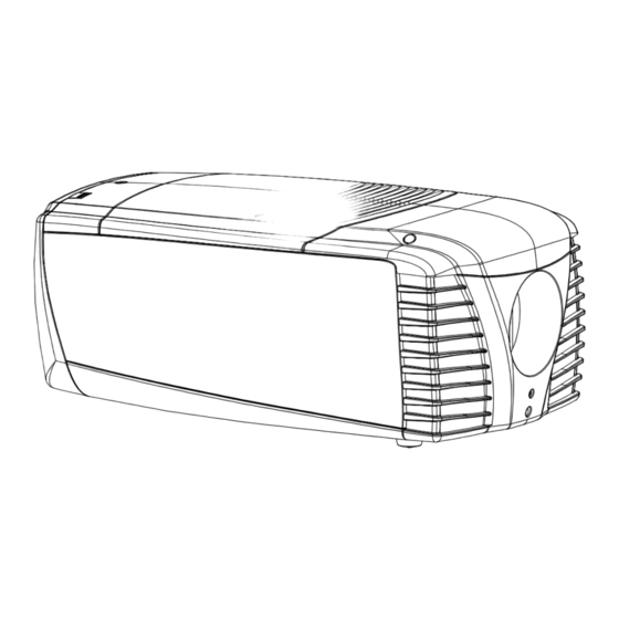
Page 181: Dimensions
A. Dimensions A. DIMENSIONS Overview • Dimensions of the CLM R10+ A.1 Dimensions of the CLM R10+ Dimensions without carry handle 691.18 Image A-1 Dimensions R59770021 CLM R10+ 07/07/2008... - Page 182 A. Dimensions Dimensions with optional carry handle 145.5 97.5 Image A-2 R59770021 CLM R10+ 07/07/2008...
-
Page 183: Standard Source Files
B. Standard Source Files B. STANDARD SOURCE FILES B.1 Table overview Table overview The following standard image files are pre-programmed in the projector. Name Fvert FHor Fpix Ptot Pact Ltot Lact 640x350@85 85,079 37,860 31,500 640x400@85 85,079 37,860 31,500 640x480@60 59,940 31,668 25,175... - Page 184 B. Standard Source Files Name Fvert FHor Fpix Ptot Pact Ltot Lact 1400x1050RB@60 59,946 64,742 100,997 1560 1400 1080 1050 1600x1200@60 60,001 75,002 162,004 2160 1600 1250 1200 1600x1200@65 64,998 81,248 175,496 2160 1600 1250 1200 1600x1200@70 69,997 87,497 188,993 2160 1600 1250...
-
Page 185: Dmx Chart
C. DMX Chart C. DMX CHART Overview • CLM control channel mapping Mode 1 • CLM control channel mapping (Simple mode) C.1 CLM control channel mapping Mode 1 Overview Chan- Function Type Range Default Action Comments Intensity Xfade 0 - 255 0 - 100% Brightness Xfade 0 - 255 128... -
Page 186: Clm Control Channel Mapping (Simple Mode)
C. DMX Chart Chan- Function Type Range Default Action Comments Motor Go << 0 - 31 Stop 31 - 63 64 - 95 Future assignment Same as Stop 96 - Future assignment Same as Stop 128 - Future assignment Same as Stop 160 - Future assignment Same as Stop... -
Page 187: Specifications
D. Specifications D. SPECIFICATIONS Overview • Specifications CLM R10+ • Specifications CLM 5 cable input (multi purpose) • Specifications CLM HDSDI – SDI input • Specifications CLM DVI input • Specifications CLM DVI HDCP input D.1 Specifications CLM R10+ Overview Light Output 9 500 ANSI Lumen 10 000 Center Lumen... -
Page 188: Specifications Clm 5 Cable Input (Multi Purpose)
D. Specifications Brightness uniformity > 85% Display 1 Chip DLP SXGA+ (resolution of 1400 x 1050 pixels (aspect ratio 4:3)) Features • DMX512 control of optical dimming, electronic dimming, zoom, focus, lens shift, input select • Advanced picture-in-picture • Seamless switching with effects •... -
Page 189: Specifications Clm Hdsdi - Sdi Input
D. Specifications Input signal R / P G / Y / VIDEO B / P H / S V / C — — RGsB sync on green — — — — Composite Video VIDEO — — — Super Video Luma Chroma —... -
Page 190: Specifications Clm Dvi Input
D. Specifications Specifications • SD SMPTE 259M-C and HD SMPTE 292M input data • 2 inputs (BNC), 1 active loop-through output (BNC) of selected input • Automatic selection of active input with manual override • 10 bit digital output • Diagnostic LED’s on front panel: Green LED: Lights up in case input module is selected Yellow LED: Lights up in case sync detected... -
Page 191: Specifications Clm Dvi Hdcp Input
D. Specifications D.5 Specifications CLM DVI HDCP input Input front view HDCP DVI input Sync OK Image D-4 Specifications • DVI type: DVI-I (DVI-Integrated), but the analog signals are not supported. Single-link configuration. • Supports UXGA Resolution (1600 x 1200) (Output Pixel Rates up to 165 MHz) •... - Page 192 D. Specifications R59770021 CLM R10+ 07/07/2008...
-
Page 193: Troubleshooting
E. Troubleshooting E. TROUBLESHOOTING Error codes Overview When the error code is preceded by a ’-’ sign, then the error means a real error for the projector. When the error code is preceded by a ’+’ sign, then the error code means a warning. The projector does not fail yet, but take care for the warning and try to resolve the problem. - Page 194 E. Troubleshooting Error Description Error Warning Action Caused by code 1693 1692 1691 1694 Formatter formatter ’Power Good’ signal not Call a qualified service engineer PWGGood 1999 MAX7301 not initialized 2000 No lps detected no communication with lamp power Call a qualified service engineer supply 2001 Mains voltage...
- Page 195 E. Troubleshooting Error Description Error Warning Action Caused by code 7992 LPS1 temp High temperature on LPS1 check if air slots are free, clean air high filters. If problem persists, call a qualified service engineer. 7990 LPS2 temp High temperature on LPS2 check if air slots are free, clean air high filters.
- Page 196 E. Troubleshooting Error Description Error Warning Action Caused by code 7912 Fan LPS A low Fan is running too slow or not at all If problem persists, call a qualified service engineer 7911 Fan LPS A high 7910 Fan LPS B low Fan is running too slow or not at all If problem persists, call a qualified service engineer...
- Page 197 E. Troubleshooting Error Description Error Warning Action Caused by code 7878 Over temp extreme overheading of DMD or If problem persists, call a qualified lamps service engineer 7877 Under temp DMD too cold Warm up the projector 7876 SMPS input Supplied voltage is out of range Check supplied voltage range range...
- Page 198 E. Troubleshooting Error Description Error Warning Action Caused by code 7851 Lamp 4 run The maximum run time for the lamp Replace the lamp with a new one. time max is exceeded Call a qualified service engineer exceeded 7850 Lamp 4 run time shtdwn exceeded 7600...
-
Page 199: Mounting Optional Carry Handle
F. Mounting optional Carry handle F. MOUNTING OPTIONAL CARRY HANDLE About this chapter This chapter describes the procedures to mount the optional carry handle to CLM projector. When this optional carry handle is mounted, the projector can be suspended with the rigging clamps and stacking of projector is possible. Overview •... -
Page 200: Preparing The New Carry Handle
F. Mounting optional Carry handle Image F-2 Mounting the stacking points 2. Place a stacking point (A) in each hole. 3. For the front stacking points, turn in for each a long bolt (B). For the back stacking point, turn in a short bolt (C). Image F-3 Stacking points mounted Preparing the new carry handle... -
Page 201: Preparing The Projector
F. Mounting optional Carry handle Image F-4 Remove stacking point construction Preparing the projector AUTION Before turning the projector upside down, be sure the stacking points on the top cover are mounted. What has to be done? Before the carry handle can be mounted, the projector feet must be removed and an extra support point must be added. How to handle 1. -
Page 202: Mounting The Carry Handle
F. Mounting optional Carry handle Image F-5 3. Insert next to the removed back foot the extra support point. 4. Place a washer on it and insert a bolt. Secure the bolt. Due to its construction, the support is still a bit movable. Image F-6 Insert extra foot 5. - Page 203 F. Mounting optional Carry handle Image F-7 Carry handle mounting Note: If both front holes are not completely free, turn on the skew adjustment (C) at the right side of the carry handle until the holes are free. 4. Place the removed stacking point construction back on its place and secure the 4 bolts and nuts. The nuts must be mounted on the inside of the carry handle.
- Page 204 F. Mounting optional Carry handle Image F-8 Mounting stacking foot R59770021 CLM R10+ 07/07/2008...
-
Page 205: Order Info
G. Order info G. ORDER INFO G.1 Spare part order info Order info: Order info Description R9854430 5 cable input module R9854450 HDSDI - SDI input module R9854460 DVI input module R848607 Cover plate for unused input slot R98610206 CLM dust filter kit, 6 pack R986102012 CLM dust filter kit, 12 pack R9861030... - Page 206 G. Order info R59770021 CLM R10+ 07/07/2008...
-
Page 207: Glossary
Glossary GLOSSARY 2:2 pull-down The process of transferring 24-frames/sec film format into video by repeating each frame (used for PAL DVD’s) as two video fields. ( AD ) 3:2 pull-down Method used to map the 24 fps of film onto the 30 fps (60 fields) or 25 fps (50 fields), so that one film frame occupies three video fields, the next two, etc. - Page 208 Glossary MAC address Media Access Control address. Unique hardware number, used in combination with the IP-address to connect to the network (LAN or WAN). PiP stands for "Picture in Picture" and allows to display multiple windows containing each of them an image. The windows may be of the video or data type.
-
Page 209: Index
Index INDEX Communication 41–43 Ethernet Address IR communication Program RS232 RS422 Adjustment 50–52 USB port Quick set up 50–52 Communication connections Lens Configurations Lens functions Front projection Lens key Rear projection Connections 37, 39–40, 49 Adjustment mode 57–58 Communication connections About Input source LCD display menus... - Page 210 Index General 11–14, 17 Copy file Air inlets Delete file 91–92 Air outlets File manipulations Box content File options Download plug-in Files Download Projector Toolset Rename file Projector configurations Save custom settings Unpacking Infra red Getting started 45, 47, 50, 53–54 Input 61–63, 65, 67–68 Auto button...
- Page 211 Index Lamp unit 167, 169 Mounting Off-Axis Removal On screen menus Language 52, 147 On-Axis Selection 52, 147 Order info Layout 97–98, 100, 102, 105–109 Spare part Copy Orientations Delete Front projection Layout file services Rear projection Layout services 106–109 Copy Delete Load...
- Page 212 Index Error logging Start up Quick language Identification Selection Internal service patterns Quick set up 50–52 Overview flow Lens 50–51 Refill mode Lens functions Restore factory defaults LENS key Safety DMD safety Text on/off Save custom settings Quick setup USB memory Versions Start up Voltages...
- Page 213 Index Cooling liquid circuit Mercury vapor warnings Versions Ultraviolet radiation Start up UV radiation Voltages White peaking Start up Window PIP window Warnings 6–7 R59770021 CLM R10+ 07/07/2008...
- Page 214 Index R59770021 CLM R10+ 07/07/2008...
- Page 215 Revision Sheet Barco nv Events/Documentation Noordlaan 5, B-8520 Kuurne Phone: +32 56.36.89.70, Fax: +32 56.36.88.24 E-mail: service.mne@barco.com, Web: www.barco.com From: Date: Please correct the following points in this documentation (R59770021/06): page wrong correct R59770021 CLM R10+ 07/07/2008...
Need help?
Do you have a question about the R9050100 and is the answer not in the manual?
Questions and answers