Table of Contents
Advertisement
Advertisement
Table of Contents

Related Manuals for FlexRadio Systems Flex-3000


Summary of Contents for FlexRadio Systems Flex-3000
- Page 1 ® ® Owner's Manual HF-6m Transceiver Version 1.18.0...
- Page 2 FlexRadio Systems. Information contained in this document may contain technical inaccuracies or typographical errors. Information may be changed or updated without notice. FlexRadio Systems may make improvements and/or changes in the materials at any time without notice. All materials are provided "as is". FlexRadio Systems makes no representations or warranties, expressed or implied to the accuracy of the copyrighted materials.
-
Page 3: Table Of Contents
INSTALLING AND CONFIGURING THE FLEXRADIO FIREWIRE DRIVER......8 Switch Off the FLEX-3000 and Install the FireWire Driver...........8 Power Up the FLEX-3000 and Install the New Hardware Found..........13 Configuring the FlexRadio Driver using the Control Panel..........16 Sampling Rate and Buffer Size ....................17 Operation Mode........................18... - Page 4 (17) MUT (MUTE).......................57 (18) REC (RECORD) AND PLAY...................57 (19) TUN (TUNE)......................57 (20) ATU AND BYP.....................58 (21) AF (AUDIO FREQUENCY GAIN)................58 (22) AGC-T (AGC MAXIMUM GAIN)................58 (23) DRIVE (TRANSMITTER POWER OUTPUT/TUNE POWER)........59 (24) AGC (AUTOMATIC GAIN CONTROL)..............59 © 2003-2009 FlexRadio Systems...
- Page 5 Scope Time Base............................79 Averaging..............................79 Polyphase FFT............................79 DSP TAB........................80 Options Sub-Tab......................80 Noise Reduction.............................80 Automatic Notch Filter..........................81 Use Peak Readings for TX Meter DSP Values....................81 Buffer Size............................82 Noise Blanker............................83 Noise Blanker 2............................83 Window ...............................83 Image Reject Sub-Tab....................85 Expert..............................85 Receive Rejection...........................86 © 2003-2009 FlexRadio Systems...
- Page 6 TESTS TAB........................110 Two Tone Test:.............................110 Audio Balance Test..........................110 Signal Generator..........................111 Enable HW Signal Generator........................112 5 OPERATING FORMS...............113 (29) MEMORY FORM....................114 Save… ........................114 Recall…........................115 (30) WAVE FORM.....................116 Playback.............................116 Playlist..............................117 Record..............................117 TX Gain (dB)............................117 Quick Rec and Quick Play........................117 © 2003-2009 FlexRadio Systems...
- Page 7 Create the Virtual Audio Cables.....................159 Setup VAC in PowerSDR.......................161 Setting up Third Party Digital Programs................162 Using MixW with PowerSDR....................162 Programs Needing to Connect to the Default Sound Device............166 7 SPECIFICATIONS AND ARCHITECTURE........169 FLEX-3000 TRANSCEIVER SPECIFICATIONS............169 FLEX-3000 ARCHITECTURE..................171 © 2003-2009 FlexRadio Systems...
- Page 8 DECLARATIONS OF CONFORMITY................172 FCC..........................172 EU Compliance......................172 A BUFFERS AND SAMPLE RATE..........173 FILTER EFFECTS.......................173 LATENCY EFFECTS....................175 UNDERLYING THEORY....................175 B UPDATING THE FLEX-3000 FIRMWARE.........179 AUTOMATICALLY......................179 MANUALLY.......................179 Download and Extract the Firmware................179 Update the Firmware....................180 C OPTIMIZING THE AGC............183 D WINDOW FUNCTIONS............185 viii...
-
Page 9: Preface
Any adjustments that you make are automatically saved and can be imported into an updated version of the software. Due to the nature of the FLEX-3000, the largest part of this operating manual, by far, will refer to software. The operating manual has numerous screenshots of windows and forms to detail the various steps. -
Page 10: Acknowledgments
Acknowledgments FlexRadio Systems could not be as successful, nor could the FLEX-3000 radio be what it is today without the many selfless contributions from our users all over the world. These contributions have spanned and continue to span improvements to our hardware and software, ranging from bug reports and feature requests to actual design and implementation of certain functionality. -
Page 11: Using This Manual In Its Pdf Form
If the hyperlink has been previously clicked, it will be shown in magenta instead of blue. [The rest of this page has been left blank intentionally] Adobe and Reader are registered trademarks of Adobe Systems, Inc. xiii © 2003-2009 FlexRadio Systems... -
Page 12: Hardware Installation
(Other items may be included that are not listed above) The FLEX-3000 power cable is unterminated at one end so that you can adapt it to various DC power connectors, such as Anderson Power Poles, Banana plugs, screw terminals or spade lugs. Connect the 2 red wires to the positive terminal and the 2 black wires to the negative terminal of your power supply. -
Page 13: Location Considerations
Location Considerations To facilitate integrating your FLEX-3000 into your shack you may want to consider the following: Place your FLEX-3000 in close proximity to your computer . It is best to use the shortest FireWire cable possible to connect to your computer to minimize data errors and limit possible RFI getting into the computer. -
Page 14: Physical Connections
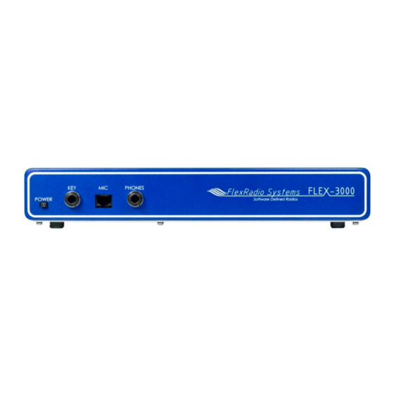
Figure 1: FLEX-3000 Front Panel (1) Power Switch The FLEX-3000 uses a delayed start push-to-latch/push-to-release switch to power up the radio. To turn on the radio, push the switch in fully to latch it in the on position. After a few seconds ... -
Page 15: Microphone Connector
Tune Step between 50Hz and 1kHz. Although the FLEX-3000 will work well with many types of microphones, it is conveniently wired to enable the use of microphones such as the Yaesu MH-31, that include buttons for Up, Down and Fast. -
Page 16: Headphone Jack
Figure 3: FLEX-300 Back Panel (1) 13.8 VDC Power Socket The FLEX-3000 requires a stable 13.8 VDC power source rated for at least 20 Amps and 25 Amps peak for proper operation. Supplied with your radio was an unterminated 4-pin keyed Molex type power connector and cable set. -
Page 17: Ieee 1394 Firewire® Jack
(4) IEEE 1394 FireWire Jack The FLEX-3000 has a 400 Mb/s 6-pin IEEE 1394 FireWire jack. This is a 1394a connection, not the 1394b (FireWire 800) type which run at 800 Mb/s. Connect the ferrite core end of the supplied 6-pin FireWire cable to this jack and connect the other end to your computer’s FireWire jack (the host... -
Page 18: Powered Speaker Jack
A family of FlexWire peripherals will be forthcoming from FlexRadio Systems. This is not another “CAT” port, but an industry standard bidirectional communications bus based on the I (pronounced “I squared C”) protocol along with AF I/O lines. -
Page 19: Installing And Configuring The Flexradio Firewire Driver
Then go to the saved zip file and extract its contents. Before proceeding with the installation, make sure the power switch on the FLEX-3000 is turned off (blue LED is off, see Figure 1 on page 3). It is also a good idea to close all other applications. - Page 20 [The rest of this page has been left blank intentionally] All screenshots in this manual are as they would appear when using the Microsoft Windows XP operating system. The screenshots may look slightly different when using Microsoft Vista, but the steps are the same. © 2003-2009 FlexRadio Systems...
- Page 21 Figure 6: FlexRadio Driver Setup Wizard - Select Destination Location We recommend you accept the default location to install the FlexRadio FireWire Driver to. Click the Next button to continue to Figure 7. [The rest of this page has been left blank intentionally] © 2003-2009 FlexRadio Systems...
- Page 22 If you do not want the Control Panel icon on your desktop, uncheck the “Create a desktop icon” option. Click the Next button to continue to Figure 8. [The rest of this page has been left blank intentionally] © 2003-2009 FlexRadio Systems...
- Page 23 [The rest of this page has been left blank intentionally] This warning is displayed because the hardware driver has not passed the formal Windows Logo Testing program. The FlexRadio driver has, however, been extensively tested and will not destabilize or impair your system © 2003-2009 FlexRadio Systems...
-
Page 24: Power Up The Flex-3000 And Install The New Hardware Found
Power Up the FLEX-3000 and Install the New Hardware Found After your computer has rebooted, press and latch the power button on the FLEX-3000 to power it up. After a brief moment, you will hear the power relay click and the blue LED will illuminate the power button. - Page 25 Select the option No, not this time when you are prompted to use Windows Update to search for software. Click on the Next button to continue to Figure 11. Note: Figure 10 above may not show up in some systems. [The rest of this page has been left blank intentionally] © 2003-2009 FlexRadio Systems...
- Page 26 Figure 11: Found New Hardware Wizard - Installing the FLEX-3000 Software The Found New Hardware Wizard will recognize that you are trying to install a FlexRadio FLEX-3000. Select the option Install the software automatically (Recommended). Click on the Next button to continue.
-
Page 27: Configuring The Flexradio Driver Using The Control Panel
After the driver files are installed you will see the Completing the Found New Hardware Wizard screen (Figure 12) to indicate that the wizard has finished installing the software for the FlexRadio FLEX-3000. Click on the Finish button to continue. You should see a prompt in the bottom right hand corner of your display that indicates that your new hardware is ready to use. -
Page 28: Sampling Rate And Buffer Size
Do not confuse this audio buffer size with the DSP buffer size (see page 82). The former applies to the transfer of samples from the radio to/from the computer; the latter applies to the transfer from the time to the frequency domain in the software. © 2003-2009 FlexRadio Systems... -
Page 29: Operation Mode
Technically these Operation Modes control how successfully the hardware driver recovers from buffer over and under runs. Some hardware drivers and third-party applications issue what are called delayed procedure calls (DPCs). Higher Safe Modes allow the driver to handle longer DPC latencies at the cost of more audio latency. © 2003-2009 FlexRadio Systems... -
Page 30: Dpc Latency Checker
C H A P T E R DPC Latency Checker Figure 14: FLEX-3000 Control Panel DPC Latency Checker The FlexRadio Driver comes with a DPC latency checker to check the maximum latency incurred on your system. To enable it click the DPC button at the top (Figure 14) and click Enable DPC Latency Checker. -
Page 31: Powersdr Installation & Setup
After reviewing the new version and verifying that your setup works, uninstalling previous versions is fine (but not necessary). Note that in order to completely remove previous versions you must manually delete the database file (PowerSDR.mdb) from the application directory (usually c:\Program Files\FlexRadio Systems\PowerSDR vn.n.n). PowerSDR Installation Download PowerSDR v1.18.0... - Page 32 S E T U P C H A P T E R Figure 16: PowerSDR Installation Welcome Screen Click the Next button to continue to Figure 17. [The rest of this page has been left blank intentionally] © 2003-2009 FlexRadio Systems...
- Page 33 You can change the installation directory here, though we recommend you use the default for troubleshooting purposes. Click the Next button to continue to Figure 18. [The rest of this page has been left blank intentionally] © 2003-2009 FlexRadio Systems...
- Page 34 Figure 18: PowerSDR Installation License Agreement Read the GNU Public License. If you accept, click I Agree and click the Next button to continue to Figure 19. Otherwise click Cancel. [The rest of this page has been left blank intentionally] © 2003-2009 FlexRadio Systems...
- Page 35 Click the Next button to confirm these settings and to copy the necessary files to the selected install directory. Once the files have been copied, you will see the screen shown in Figure 20. [The rest of this page has been left blank intentionally] © 2003-2009 FlexRadio Systems...
-
Page 36: Powersdr Setup Wizard
PowerSDR Setup Wizard Power up the FLEX-3000 to load its driver and start up the PowerSDR console using the shortcut on the Desktop (or through the Start menu). When you run a new release of PowerSDR for the first time an optimization routine will run and the screens shown in Figure 21 will appear. - Page 37 When the routine has completed, a brief startup sequence will follow, after which a warning regarding mobile operation is appears, as shown in Figure 22 below. [The rest of this page has been left blank intentionally] © 2003-2009 FlexRadio Systems...
- Page 38 Figure 22: PowerSDR Setup Wizard Welcome Click the Continue button to continue to Figure 23. Figure 23: PowerSDR Setup Wizard - Radio Model Select the FLEX-3000 radio model as shown in Figure 23 above. Click the Next button to continue to Figure 24. Note: If you are running without a radio, e.g.
- Page 39 The Setup Wizard is now complete. Click the Finish button to complete the wizard. Note: If you forgot to power up the FLEX-3000 before starting PowerSDR, a communication error message will be displayed and PowerSDR will offer the ability to start in demo mode. Click No to close PowerSDR, power up the FLEX-3000 and restart PowerSDR.
-
Page 40: Initial Powersdr Configuration
C H A P T E R Initial PowerSDR Configuration Before operating the FLEX-3000 several PowerSDR parameters need to be configured. To do so, start up PowerSDR to open the Front Console, but do not yet click on the Start button. - Page 41 PowerSDR will initially start with a default database. If you find your radio is not performing as you expect, please manually delete the database file (PowerSDR.mdb) from the application directory (usually c:\Program Files\FlexRadio Systems\PowerSDR vn.n.n). PowerSDR will then again start with a default database.
-
Page 42: Audio Parameters
Audio tab and then the Primary sub-tab shown in Figure 28. Figure 28: Setup Form - Audio Tab, Sound Card Sub-Tab Change the Buffer Size to the same value you entered in the FLEX-3000 Control Panel (see Figure 13 on page 17). Click on the OK button when done. -
Page 43: Completely Factory Calibrated
You are now ready to use your FLEX-3000. Click on Start on the Front Console and you should hear receive audio. If you do not, double check all your connections and settings (especially for the Mixer form). -
Page 44: Front Console
Up/Down controls are similar to a Text Box, but are limited to numeric input. They also have arrows for simple increment/decrement behavior. [The rest of this page has been left blank intentionally] © 2003-2009 FlexRadio Systems... - Page 45 F R O N T C O N S O L E C H A P T E R Figure 31: FLEX-3000 PowerSDR 1.18.0 Front Console Note: The front console controls the basic functions of the radio: frequency, mode, filters, and display. In addition to these basic features, there are many other controls that are described in detail below.
-
Page 46: Vfo A
Arrow) to tune the radio. Rotating the mouse wheel away from you will increase the frequency by the step rate per click while rotating the wheel toward you will decrease the frequency. You can change the © 2003-2009 FlexRadio Systems... -
Page 47: Vfo B
Alternatively a bar graph display can be selected (see the description of the Setup Form - Appearance Tab, Meter Sub-Tab on page 102). [The rest of this page has been left blank intentionally] © 2003-2009 FlexRadio Systems... -
Page 48: Rx Meters
Sig Avg (Signal Average): Calculates the true RMS power in dBm of a time-averaged signal within the passband, as measured at the selected FLEX-3000 antenna port. ADC L (Analog To Digital Left): Calculates the level in dBFS (decibel full scale) of the Left ... -
Page 49: Band Selection & Band Stacking Memories
The modified memories will be saved to the database upon graceful exit of the console. A crash will prevent changed memories from being saved in order to keep faulty data out of the database. Note : Some band memory frequencies (such as 60m and WWV) are fixed in software and cannot be changed. © 2003-2009 FlexRadio Systems... -
Page 50: Mode Selection
DRM: Digital Radio Mondiale (requires licensed external demodulator software not available from FlexRadio Systems; Enables VAC if VAC Auto Enable is engaged, see page 74) Hotkeys are available in the Setup-Form, Keyboard Tab to cycle through the various modes using the keyboard (see page 104). -
Page 51: Filter Controls
Each of the 10 labeled filter buttons can be customized for any of the modes. To do so, right click on a filter button and select Configure… to bring up the screen shown in Figure 40. [The rest of this page has been left blank intentionally] © 2003-2009 FlexRadio Systems... -
Page 52: Variable Filter Buttons
Shift: Shifts the selected filter passband up or down from its normal center frequency. This can help to eliminate interference caused by signals in close proximity of the received signal. The behavior of this control is set in the Setup Form – General Tab, Filter Sub-Tab (page 70). © 2003-2009 FlexRadio Systems... -
Page 53: Mode Specific Controls
DX: click to enable the DX compander (a form of compression), which has been optimized to give your voice an extra punch, especially useful in DX situations. Adjust its level with either the slider or the text box. © 2003-2009 FlexRadio Systems... -
Page 54: Cw Controls
The CW controls, shown in Figure 42 below are available when either CWL or CWU is selected. Most of these controls can be found on the Setup Form-DSP Tab, Keyer Sub-Tab (see page 87, where you can also find a more detailed description). [The rest of this page has been left blank intentionally] © 2003-2009 FlexRadio Systems... - Page 55 Break In: check the Enabled box to activate Break In for the internal keyer. Set the delay in the Delay text box. See also page 89. [The rest of this page has been left blank intentionally] ClickTune is a trademark of FlexRadio Systems. © 2003-2009 FlexRadio Systems...
-
Page 56: Digital Controls
The main display controls, shown in Figure 44 below, consist of two sections: Screen adjustment controls and display selection controls. The former act on the screen as a whole, where as the latter determine the display type to be used. [The rest of this page has been left blank intentionally] © 2003-2009 FlexRadio Systems... -
Page 57: Screen Controls
) and three time domain display types (Scope, Phase and Phase2). All the colors used in the display (text, data line, background, etc) are completely customizable using the Setup Form-Appearance Tab, Display Sub-Tab (page 97). Panafall is a trademark of FlexRadio Systems. Panascope is a trademark of FlexRadio Systems. © 2003-2009 FlexRadio Systems... -
Page 58: Spectrum
RX filter (green, VFO-A), the MultiRX filter (blue, VFO-B) and the TX filter edges (yellow vertical lines). The color of all the filter overlays can be changed independently using the Setup Form-Appearance Tab, Display Sub-Tab (page 97). © 2003-2009 FlexRadio Systems... -
Page 59: Histogram
The green signals are previous peaks on that same frequency that will fade as time goes by (a type of history, hence the name). [The rest of this page has been left blank intentionally] © 2003-2009 FlexRadio Systems... -
Page 60: Waterfall
The Waterfall Display can be customized on the Setup Form- Display Tab This allows custom setting of the dynamic range and coloring for the display. (See the Setup Form-Display Tab on page 77 for more details.) [The rest of this page has been left blank intentionally] © 2003-2009 FlexRadio Systems... -
Page 61: Scope
If the circle distorts into an oval or a straight line, the input phase is off balance which would indicate a connection or hardware problem. [The rest of this page has been left blank intentionally] © 2003-2009 FlexRadio Systems... -
Page 62: Panafall
Another feature of the crosshairs is ClickTuning. Clicking the left mouse button with the yellow crosshairs visible tunes VFO A to the frequency indicated by the cursor position data (or if Snap ClickTune is on (see page 67), to the nearest multiple of the Tune Step). The red crosshairs © 2003-2009 FlexRadio Systems... -
Page 63: Multirx Controls
NR (DSP Noise Reduction): Activates the DSP Noise Reduction algorithm (see page 80). ANF (Automatic Notch Filter): Activates the Automatic Notch Filter algorithm. NB (Impulse Noise Blanker): Activates the Noise Blanker algorithm (see page 83). © 2003-2009 FlexRadio Systems... -
Page 64: Vfo Controls
A >B: Transfers the contents of VFO A to VFO B (frequency, mode, and filter). A< B: Transfers the contents of VFO B to VFO A (frequency, mode, and filter). A< >B: Swaps the contents of VFO A and B (frequency, mode, and filter). © 2003-2009 FlexRadio Systems... -
Page 65: Cpu
Frequency (IF, usually 9kHz). In voice operation the MON feature will allow you to hear the effects of MIC gain, TX equalization, compression and compansion and to adjust them in real time. The AF control can be used to adjust the monitor volume. [The rest of this page has been left blank intentionally] © 2003-2009 FlexRadio Systems... -
Page 66: Mox (Manually Operated Transmit)
Drive control while TUN is activated. Any changes to the Drive control while TUN is active are saved when the TUN button is turned off. [The rest of this page has been left blank intentionally] © 2003-2009 FlexRadio Systems... -
Page 67: Atu And Byp
This control sets the maximum gain of the AGC. It is the same control as can be found on the Setup Form-DSP Tab, AGC/ALC Sub-Tab (page 90). The operational use of the AGC control is essentially the same as that of an RF gain control found in more traditional receivers. © 2003-2009 FlexRadio Systems... -
Page 68: Drive (Transmitter Power Output/Tune Power)
The RX Gain is in actual fact a 26dB preamp combined with a 20dB attenuator. This control enables selection of the preamp/attnenuator states: ATTN, Off, and Pre. The corresponding preamp and attenuator settings are shown in Table 6. Table 6: RX Gain Details Gain Net Gain Setting (20dB) (26dB) (dB) Attn © 2003-2009 FlexRadio Systems... -
Page 69: Sql (Squelch)
Each of these items opens a form, which is used while operating. Please refer to the Operating Forms chapter below for more detailed information on each one. [The rest of this page has been left blank intentionally] © 2003-2009 FlexRadio Systems... -
Page 70: Setup Form
Note: The database saves all of the radio options and its current state. It also contains the data read from the EEPROM in your FLEX-3000. If you have used the default directory during installation as recommended, the database file will be in C:\Program Files\FlexRadio Systems\PowerSDR vn.n.n\. The database file is called PowerSDR.mdb. - Page 71 Cancel: Reloads the values from the database into the Setup Form and closes the form. This button can be used to reverse unintended changes to the Setup controls. Apply: Immediately saves the current values to the database. [The rest of this page has been left blank intentionally] © 2003-2009 FlexRadio Systems...
-
Page 72: General Tab
Check this box to use only the receiver, while disabling the transmitter. When checked, MOX, TUN and VOX will become unavailable on the Front Console and PTT (either via the MIC connector or the back panel PTT connector) will also not function. [The rest of this page has been left blank intentionally] © 2003-2009 FlexRadio Systems... -
Page 73: Radio Model
ATU, is just marked as “Present”. Figure 62: DDS DDS Stands for Direct Digital Synthesis. The DDS chip in the FLEX-3000 produces an analog sine wave at up to micro Hertz resolution. The DDS is used as a local oscillator to tune the radio. -
Page 74: Options Sub-Tab
However, if you are experiencing low frequency noise, such as spurs that cannot be eliminated with the Spur Reduction (SR) enabled, you might try adjusting the IF. Options Sub-Tab Figure 63: Setup Form - General Tab, Options Sub-Tab © 2003-2009 FlexRadio Systems... -
Page 75: Options
Systems recommends using the Normal setting, if you are experiencing audio glitches or are using a slower machine, selecting Above Normal or High might improve the performance of the software. Note that FlexRadio Systems does not recommend using the Real Time setting as this could cause timing problems with the operating system. -
Page 76: Clicktune Offsets (Hz)
– RIT frequency. This can be useful if you want to zero beat the receive frequency without changing the transmit frequency. Mouse Tune Step: When checked, clicking the mouse button (middle click) will cycle through the tune steps. [The rest of this page has been left blank intentionally] © 2003-2009 FlexRadio Systems... -
Page 77: Keyboard
VFO frequency due to accidental key presses. Custom Title Text Enter the text you would like appended to the standard text (FlexRadio Systems PowerSDR v1.n.n) in the title bar of the Front Console. [The rest of this page has been left blank intentionally]... -
Page 78: Calibration Sub-Tab
If you decide to proceed tune your radio to a known accurate frequency source (e.g. WWV), enter the frequency in the Frequency control and click the Start button. [The rest of this page has been left blank intentionally] © 2003-2009 FlexRadio Systems... -
Page 79: Filters Sub-Tab
Filter Low and High Cut controls on the front panel. Default Low Cut (Hz): Sets the default low frequency cut-off for the USB/LSB filters. [The rest of this page has been left blank intentionally] © 2003-2009 FlexRadio Systems... -
Page 80: Audio Tab
It is this trade-off that needs to be made, especially for CW where latency is more critical. [The rest of this page has been left blank intentionally] © 2003-2009 FlexRadio Systems... -
Page 81: Mic Boost
C H A P T E R Note: The FLEX-3000 Driver will not automatically follow your audio Buffer Size, so make sure they are both set identically (see page 17), as a mismatch can lead to audio pops and clicks. The Driver will, however, follow the sample rate setting in PowerSDR. -
Page 82: Vac Sub-Tab
Virtual Audio Cable Setup Select the driver type you wish to use. With most digital software MME will work well. Select the Input and Output channels as shown in Figure 71. Gain (dB) Figure 72: Gain (dB) Controls © 2003-2009 FlexRadio Systems... -
Page 83: Latency
Allow PTT to override/bypass VAC for Phone Check this box if you wish to override or bypass VAC when activating PTT, e.g. to use your microphone. [The rest of this page has been left blank intentionally] © 2003-2009 FlexRadio Systems... -
Page 84: Direct Iq
I/Q signals. Check Calibrate I/Q to correct the raw I/Q signal and avoid any image signals going to the third-party software. [The rest of this page has been left blank intentionally] © 2003-2009 FlexRadio Systems... -
Page 85: Display Tab
Max: The maximum displayed signal level in dBm (i.e. top of the display). Min: The minimum displayed signal level in dBm (i.e. bottom of the display). Step: Spacing between the horizontal grid lines in dBm. © 2003-2009 FlexRadio Systems... -
Page 86: Refresh Rates
will use the Low Color. High Level: The high end of the dynamic range to view in dBm. Low Color: Color used if the signal level is at or below the Low Level. © 2003-2009 FlexRadio Systems... -
Page 87: Multimeter
Show Decimal: Check to show decimal values in the digital meter. Phase Resolution Figure 80: Phase Resolution This control sets the Phase display resolution in number of points displayed per 360°. [The rest of this page has been left blank intentionally] © 2003-2009 FlexRadio Systems... -
Page 88: Scope Time Base
Histogram). Expect to see an up to 4 times narrower area of the displayed “spike” of a tone, especially when the displayed frequency span is relatively large in comparison. [The rest of this page has been left blank intentionally] © 2003-2009 FlexRadio Systems... -
Page 89: Dsp Tab
Noise Reduction (NR) attempts automatic computation of a filter that maximizes the coherent or non- noise like signals and as a result, filters out the rest of the signal, which includes noise. It is best used for speech signals with a good signal to noise ratio or tones. © 2003-2009 FlexRadio Systems... -
Page 90: Automatic Notch Filter
Use Peak Readings for TX Meter DSP Values When checked, the MIC, EQ, Leveler, CPDR and ALC TX Meters will show peak values instead of RMS values. [The rest of this page has been left blank intentionally] © 2003-2009 FlexRadio Systems... -
Page 91: Buffer Size
512/96000 = 5ms. In this case the overall latency is determined by the DSP buffer size and the group delay of 11ms. The same filter shape is achieved for 48kHz and 512. At 96kHz, the minimim filter width reduces to approx. 281Hz, still considerably more than 25Hz. © 2003-2009 FlexRadio Systems... -
Page 92: Noise Blanker 2
(=wider filter). Appendix D describes in more detail several of the window functions available in PowerSDR. These window selections only effect the display; for the audio the window has been fixed to Blackman-Harris. © 2003-2009 FlexRadio Systems... - Page 93 Harris will be preferred, except possibly for weak CW signals, where both stop bands disappear in the noise and where dynamic range is much less important than a narrower passband. Figure 89: 25Hz CW Filter with Hanning (Red) and Blackman-Harris (Blue) Windows [The rest of this page has been left blank intentionally] © 2003-2009 FlexRadio Systems...
-
Page 94: Image Reject Sub-Tab
Image Reject Sub-Tab Figure 90: Setup Form - DSP Tab, Image Reject Sub-Tab Note: Your FLEX-3000 is completely calibrated, including both receive and transmit image rejection and needs no further adjustments. Expert This Expert check box will show controls that you should only consider using if you are an experienced user. -
Page 95: Receive Rejection
3. If the radio is set to USB, look at the image signal BELOW the carrier in either the spectrum analyzer or the second receiver. If set to LSB, look at the image signal ABOVE the carrier. © 2003-2009 FlexRadio Systems... -
Page 96: Keyer Sub-Tab
The display will continue to read the actual carrier frequency, but the software will provide for an offset to get the desired CW tone. This pitch will determine the automated tuning frequency using the display and mouse “ClickTune” functions. [The rest of this page has been left blank intentionally] © 2003-2009 FlexRadio Systems... -
Page 97: Connections
Primary: Select the connection to be used for the primary connection. Selecting “Radio” allows the use of the jack on the back of the FLEX-3000. Secondary: Select the connection to be used for the secondary connection. Selecting “CAT” ... -
Page 98: Signal Shaping
Delay (ms): Sets the amount of time between the last detected input and when the radio will drop back to receive. The smallest possible setting is 10 ms. [The rest of this page has been left blank intentionally] © 2003-2009 FlexRadio Systems... -
Page 99: Agc/Alc Sub-Tab
Max Gain (dB): The maximum amount of gain allowed by the AGC system for signals below the AGC threshold. The total AGC gain equals the Max Gain + the Slope (Gain). See also Appendix C. © 2003-2009 FlexRadio Systems... -
Page 100: Leveler
The Compander (DX and CPDR on the Front Console (see Mode Specific Controls – Phone on page 44) work very well with the ALC to increase average power without overdrive. [The rest of this page has been left blank intentionally] © 2003-2009 FlexRadio Systems... -
Page 101: Transmit Tab
To change profiles, select the named profile from the drop down list. To remove a profile, select it using the drop down menu, and then click the Delete button. [The rest of this page has been left blank intentionally] © 2003-2009 FlexRadio Systems... -
Page 102: Transmit Filter
Front Console (sets the Drive control). Changes made to the Drive level while TUN is active will be reflected in this control. TX Meter: Selects which TX Meter to use when TUN on the Front Console is clicked. [The rest of this page has been left blank intentionally] © 2003-2009 FlexRadio Systems... -
Page 103: Noise Gate
Sensitivity: The threshold above which PowerSDR automatically starts transmitting. Use this in combination with the Noise Gate for best results. Delay (ms): Time to stay in transmit after the last peak above the threshold. © 2003-2009 FlexRadio Systems... -
Page 104: Monitor
107. To use one of these, click to select it from the list and then click Import. It will now be active and show up in the Profiles list described above. [The rest of this page has been left blank intentionally] © 2003-2009 FlexRadio Systems... -
Page 105: Pa Settings Tab
C H A P T E R PA Settings Tab Figure 108: Setup Form - PA Settings Tab The FLEX-3000 is fully calibrated and requires no further adjustments. If you suspect your power amplifier requires adjustments, please first contact FlexRadio Support (on our website www.flex-... -
Page 106: Appearance Tab
Appearance Tab The appearance controls allow the user to completely customize the appearance of the front console. Display Sub-Tab Figure 109: Setup Form-Appearance Tab, Display Sub-Tab [The rest of this page has been left blank intentionally] © 2003-2009 FlexRadio Systems... -
Page 107: Overall Display
Peak Text: The color of the Peak signal location text located under the display. Background: The background color of the Peak signal location text. [The rest of this page has been left blank intentionally] © 2003-2009 FlexRadio Systems... -
Page 108: Panadapter
Show Freq. Offset: When selected, the offsets from the Main RX Filter 0Hz line are shown across the top as opposed to the actual frequencies. [The rest of this page has been left blank intentionally] © 2003-2009 FlexRadio Systems... -
Page 109: General Sub-Tab
These controls change the appearance of the buttons and the VFOs. Figure 113: Setup Form-Appearance Tab, General Sub-Tab Button Selected: The color of buttons when they are in the selected state. [The rest of this page has been left blank intentionally] © 2003-2009 FlexRadio Systems... -
Page 110: Vfo
Active: The color of the band information text when that VFO is active. Out Of Band: The background color of the VFO band information when outside the amateur radio bands. Background: The background color of the VFO band information when inside the amateur radio bands. © 2003-2009 FlexRadio Systems... -
Page 111: Meter Sub-Tab
Edge displays an analog edge style meter. Digital Text: The color of the text of the digital meter. Digital Background: The background color of the digital meter. [The rest of this page has been left blank intentionally] © 2003-2009 FlexRadio Systems... -
Page 112: Original Style
High Color: The color of the high values of the edge meter’s scale. Background: The background color of the edge meter. Indicator: The color of the indicator in the edge meter. [The rest of this page has been left blank intentionally] © 2003-2009 FlexRadio Systems... -
Page 113: Keyboard Tab
Band, Filter, Mode, RIT, or XIT up or down using the drop down controls in the respective sections. Note: Choosing any of the arrow keys will require using Alt + [arrow key]. [The rest of this page has been left blank intentionally] © 2003-2009 FlexRadio Systems... -
Page 114: Cat Control Tab
N8VB’s vCOM virtual serial port software (see page 149), interaction is possible with programs such as Ham Radio Deluxe (HRD), DXLab, N1MM Contest Logger, MixW and numerous other third-party software (aids). [The rest of this page has been left blank intentionally]john © 2003-2009 FlexRadio Systems... -
Page 115: Cat Control
Parity: Sets whether to send a parity bit. Data: Sets how many data bits are sent with each byte. Stop: Sets whether to send a stop bit. [The rest of this page has been left blank intentionally] © 2003-2009 FlexRadio Systems... -
Page 116: Ptt Control
FlexProfiler is provided free, courtesy of K5KDN and can be installed from the SVN subversion control location: svn://206.216.146.154/svn/repos_sdr_windows/FlexProfiler/trunk/bin/Release . To do so, you will need to use a program like TortoiseSVN, downloadable for free from http://tortoisesvn.tigris.org/ . Search for SVN on our Knowledge Center at http://kc.flex-radio.com/search.aspx for further information. © 2003-2009 FlexRadio Systems... -
Page 117: Test
Execute button is clicked. Typing the semicolon, the CAT terminator, at the end of the command is optional. The CAT response will appear in the CAT Response text box.. Figure 123: CAT Command Tester Form [The rest of this page has been left blank intentionally] © 2003-2009 FlexRadio Systems... -
Page 118: Rtty Offset
This differs from ClickTune Offsets (see page 65), as the ClickTune Offsets actually change the Front Console VFO frequency, whereas the RTTY Offset only offsets the frequency reported by CAT. [The rest of this page has been left blank intentionally] © 2003-2009 FlexRadio Systems... -
Page 119: Tests Tab
Powered Speaker/Line out jack on the Back Panel. [The rest of this page has been left blank intentionally] © 2003-2009 FlexRadio Systems... -
Page 120: Signal Generator
DSP. It is used to test the PowerSDR. Mode: Select the type of signal to generate. “Soundcard” means the Signal Generator is turned off and FLEX-3000 hardware can be used. Note: When finished with the Signal Generator, do not forget to place the Signal Generator back to “Soundcard”. -
Page 121: Enable Hw Signal Generator
In actual fact, the RF signal is generated using the transmit DSP and sent through the QSE (Quadrature Sampling Exciter), which is then looped back to the QSD (Quadrature Sampling Detector) and the receive DSP. [The rest of this page has been left blank intentionally] © 2003-2009 FlexRadio Systems... -
Page 122: Operating Forms
127). For ease of reference, the numerical identifiers from the previous chapter on the Front Console are repeated in this chapter. Additionally, the key combination Ctrl-Shift-I activates the voltage and temperature form (see page 129) Figure 127: Operating Form Identifiers [The rest of this page has been left blank intentionally] © 2003-2009 FlexRadio Systems... -
Page 123: Memory Form
OK button will save the information shown above into the memory database before closing the form. Clicking Cancel simply closes the form (the data is not saved). [The rest of this page has been left blank intentionally] © 2003-2009 FlexRadio Systems... -
Page 124: Recall
Select Close on Recall to close the Memory Form when clicking Recall. Delete: Click the Delete button to remove a memory from the database. A prompt will be shown to prevent unintended loss of memories. © 2003-2009 FlexRadio Systems... -
Page 125: Wave Form
The Wave form allows the user to Record and Playback either the post-processed audio of the current station, or up to 96kHz bandwidth (as determined by the audio sample rate setting) of pre-processed IF (I and Q) “audio” from the FLEX-3000. Playback Currently Playing: Displays the filename of the currently playing wave file. -
Page 126: Playlist
Quick Rec will overwrite any audio file previously recorded in this way. These two buttons perform the same function as the Rec and Play buttons on the Front Console (see page 57). [The rest of this page has been left blank intentionally] © 2003-2009 FlexRadio Systems... -
Page 127: Record Options
Sample Rate Sets the sample rate at which the wave file will be recorded. [The rest of this page has been left blank intentionally] © 2003-2009 FlexRadio Systems... -
Page 128: Equalizer Form
Easily compare the audio with and without the equalizer using the Enabled check box. The Reset button will reset all of the sliders to the 0dB position. Hint: Hover with your mouse over a slider to see its frequency range of operation. © 2003-2009 FlexRadio Systems... -
Page 129: 10-Band Equalizer
The 10-Band Equalizer offers a finer degree of audio frequency control than does the 3-band equalizer. You may want to use this equalizer if the 3-band equalizer does not give you the result you want. [The rest of this page has been left blank intentionally] © 2003-2009 FlexRadio Systems... -
Page 130: Xvtrs Form
Begin Frequency (MHz): The lower frequency bound for the transverter. End Frequency (MHz): The upper frequency bound for the transverter. RX Gain (dB): Amount of gain to apply to the incoming signals to compensate for gain within the transverter. © 2003-2009 FlexRadio Systems... - Page 131 Power control on this form (see above). Otherwise, the Tune Power setting on the Setup Form – Transmit Tab (page 92) will be used. [The rest of this page has been left blank intentionally] © 2003-2009 FlexRadio Systems...
-
Page 132: Cwx Form
Repeat Delay: This control specifies the amount of time that the keyer will wait when a special pause character is encountered. Drop Delay: This control specifies the amount of time that the semi-break in keying will wait before dropping the transmitter when there is no keying occurring. © 2003-2009 FlexRadio Systems... -
Page 133: Cwx Memories
The remaining special characters & ‘ ) : ; < > [ ] and ^ are undefined and may be defined to produce any combination of nine contiguous dots and dashes. Characters that are undefined have no dots and dashes and are simply sent as a space. [The rest of this page has been left blank intentionally] © 2003-2009 FlexRadio Systems... -
Page 134: Keyboard And Extended Controls
Pressing Alt 1 to Alt 9 or right clicking on the message number button will cause the numbered message memory to be copied into the unsent area just as if you had typed it. The ditto character is ignored in the keyboard mode. © 2003-2009 FlexRadio Systems... -
Page 135: Morse Definition Editor
The editor dialog example above shows the ‘]’ character being changed to send didahdidah which is the German code for ä (umlaut a). When your definition appears to be correct, click the Save button and the definition file will be resaved to the disk. © 2003-2009 FlexRadio Systems... - Page 136 If you mess this file up too badly, simply close PowerSDR, delete morsedef.txt, and a clean, default copy will be created the next time you start. The editor makes simple changes relatively easy to do. [The rest of this page has been left blank intentionally] © 2003-2009 FlexRadio Systems...
-
Page 137: Mixer
C H A P T E R (34) Mixer Figure 138: Audio Mixer Form The Mixer controls the audio lines into and out of the FLEX-3000. In essence it is no different than the usual Windows sound card mixer. Input The FLEX-3000 has two possibles sources of input audio. -
Page 138: Voltage And Temperature Information
The keyboard combination Ctrl-Shift-I will display the voltage and temperature. Clicking on the temperature will alternate its value between Celsius and Fahrenheit. Either value may be displayed against a yellow or red background indicating increasing levels of criticality. [The rest of this page has been left blank intentionally] © 2003-2009 FlexRadio Systems... -
Page 139: Operation
Chapter Operation This chapter is intended to provide the user with a clear understanding of how the FLEX-3000 should be used when performing basic operations such as Powering Up or making a voice transmission. We chose to use this section in this way in lieu of listing all of the features of the radio since the feature list would essentially repeat the information given in the three preceding chapters. -
Page 140: Power-Up Procedure
Boot up the computer and make sure PowerSDR is ready to be launched (no hour glass cursor). Turn on the power supply for the radio and press the FLEX-3000 power switch to latch it in the on position. After a few seconds you will hear the internal power relay click and see the blue LED illuminate. -
Page 141: Tuning Methods
When in CW, AM, SAM, DSB, FM, or DRM the VFO will tune the cursor frequency to the center of the filter pass band. In SSB the VFO will tune to the carrier frequency for the sideband selected. © 2003-2009 FlexRadio Systems... -
Page 142: Keyboard Keys
(All these documents and more can be found by searching for either PowerMate or ShuttlePro on our Knowledge Center at http://kc.flex-radio.com/search.aspx) [The rest of this page is intentionally left blank] © 2003-2009 FlexRadio Systems... -
Page 143: Voice Operation
Figure 31 on page 36 and for clarity we have left out any identifiers of controls not referenced. Note: In this chapter, we will only describe basic operation [The rest of this page has been left blank intentionally] © 2003-2009 FlexRadio Systems... - Page 144 50 ohm load with a low SWR. Failing to do so may damage the FLEX-3000 output transistors. Press the Push-to-talk button on the microphone or click the MOX (16) button and speak into the microphone to transmit your voice.
- Page 145 (page 71) and/or DSP tab, Options sub-tab (page 80) of the Setup Form. Make sure that when changing the Audio Buffer Size, you first Stop (14) PowerSDR and make the same change in the FLEX-3000 Driver (see page 17) before Starting PowerSDR again. See also Appendix A.
-
Page 146: Cw Operation
Figure 31 on page 36 and for clarity we have left out any identifiers of controls not referenced. [The rest of this page has been left blank intentionally] © 2003-2009 FlexRadio Systems... -
Page 147: Initial Settings
If you are not using the internal ATU then connect a 50 ohm dummy load, or ensure that the antenna presents a 50 ohm load with a low SWR. Failing to do so may damage the FLEX-3000 output transistors. [The rest of this page has been left blank intentionally]... -
Page 148: Internal Keyer
If using PowerSDR’s internal keyer, open the Setup Form – DSP Tab, Keyer Sub-Tab shown in Figure 142 below. Several of the controls in this form are also available in the Mode Specific Controls – CW (8) section on the Front Console. [The rest of this page has been left blank intentionally] © 2003-2009 FlexRadio Systems... - Page 149 5. You are now ready to begin a QSO. If a 50 ohm dummy load was connected, connect an antenna in its place. Tune to the desired frequency using one of the methods outlined in the Tuning Methods section above. Select either CWL or CWU (6) and proceed with the QSO. © 2003-2009 FlexRadio Systems...
-
Page 150: External Keyer
2. You are now ready to begin a QSO. If a 50 ohm dummy load was connected, connect an antenna in its place. Tune to the desired frequency using one of the methods outlined in the Tuning Methods section above. Select either CWL or CWU (6) and proceed with the QSO. © 2003-2009 FlexRadio Systems... -
Page 151: Third Party Program
CAT Control Tab. This will open up two additional selection boxes. Set PTT Line to DTR and Key Line to RTS as shown above. 3. In MixW, click Configure on the Menu bar and then select TRCVR CAT/PTT to open the screen shown in Figure 145. © 2003-2009 FlexRadio Systems... - Page 152 C H A P T E R Figure 145: MixW PTT & CAT 4. On the PTT & CAT Interface, click on the Details button to open the following form (Figure 146): [The rest of this page has been left blank intentionally] © 2003-2009 FlexRadio Systems...
- Page 153 Tune to the desired frequency using one of the methods outlined in the Tuning Methods section above. Select either CWL or CWU (6) and proceed with the QSO. [The rest of this page has been left blank intentionally] © 2003-2009 FlexRadio Systems...
-
Page 154: Digital Operation
Figure 31 on page 36 and for clarity we have left out any identifiers of controls not referenced. Follow the Power Up Procedure, described on page 132. Then click the Start button (14). Set the following controls as specified in Table 11. © 2003-2009 FlexRadio Systems... - Page 155 50 ohm load with a low SWR. Failing to do so may damage the FLEX-3000 output transistors. Click on the Transmit button of your digital mode program. It should switch PowerSDR to transmit.
- Page 156 If you already have VCOM and VAC up and running, you may ignore the following sub-sections. We will now focus on installing and setting up N8VB’s VCOM driver and VAC. We will then use MixW as an example on how to use these utilities to operate digital modes. © 2003-2009 FlexRadio Systems...
-
Page 157: Cat Control Setup
(N8VBvCOMSetup-226a.exe) and double-click to start the Windows installer. The following screen will appear (Figure 148). Figure 148: VCOM Installer Language Select your language of choice and click OK. The welcome screen appears (Figure 149). [The rest of this page has been left blank intentionally] © 2003-2009 FlexRadio Systems... - Page 158 O P E R A T I O N C H A P T E R Figure 149: VCOM Installer Welcome Screen. Click the Next button to continue the driver installation (Figure 150). [The rest of this page has been left blank intentionally] © 2003-2009 FlexRadio Systems...
- Page 159 O P E R A T I O N C H A P T E R Figure 150: VCOM License Agreement. Review the License Agreement and click the I Agree button. [The rest of this page has been left blank intentionally] © 2003-2009 FlexRadio Systems...
- Page 160 O P E R A T I O N C H A P T E R Figure 151: VCOM Installer Component Selection. Select the components you wish to install and click the Next button. [The rest of this page has been left blank intentionally] © 2003-2009 FlexRadio Systems...
- Page 161 C H A P T E R Figure 152: VCOM Install Location Choose the folder in which to install the driver application in and click the Install button. [The rest of this page has been left blank intentionally] © 2003-2009 FlexRadio Systems...
- Page 162 Click the Finish button to complete the installation of VCOM. The virtual serial port driver will now be installed on your system. A Command Prompt window displaying status messages will open followed by the warning screen shown in Figure 154 below. [The rest of this page has been left blank intentionally] © 2003-2009 FlexRadio Systems...
-
Page 163: Configure The Vcom Port Pairs
By default VCOM will install 4 COM port pairs. To view these pairs, to change the default or to remove → the driver, locate and start the VCOMConfigurator application (Start All Programs). Figure 155: VCOMConfigurator Application This will open the following screen (Figure 156). [The rest of this page has been left blank intentionally] © 2003-2009 FlexRadio Systems... - Page 164 PowerSDR software. Start up the program and pull up the CAT Control Tab on the Setup Form. For the purpose of this example, we will use the COM6-COM16 pair. [The rest of this page has been left blank intentionally] © 2003-2009 FlexRadio Systems...
-
Page 165: Configure Powersdr Cat Control
COM port number. In such a case swap COM6 to COM16 above and connect the digital program to COM6. Alternatively, create an even lower virtual Com port number (e.g. COM3), that is not physically present. [The rest of this page has been left blank intentionally] © 2003-2009 FlexRadio Systems... -
Page 166: Configure Powersdr Keyer Connections
Within the Connections Group, set Primary to the port you have your paddles or straight key connected to (Figure 158 shows Radio to indicate the FLEX-3000 front panel key jack). Set Secondary (used for keyers and programs) to CAT to use the same (virtual) COM port used for CAT Control. Set PTT Line to DTR and Key Line to RTS. -
Page 167: Virtual Sound Connection
Figure 159: VAC Connects Audio Digitally Between PowerSDR and a Digital Mode Program Create the Virtual Audio Cables The first step is to create the two identical virtual cables. To do so open the Virtual Audio Control Panel. [The rest of this page has been left blank intentionally] © 2003-2009 FlexRadio Systems... - Page 168 Set for each cable when completed. Do not close the Control Panel just yet. Note: Do NOT check the Volume Control box in the VAC control panel. This enables the Windows Mixer and can cause unpredictable results. [The rest of this page has been left blank intentionally] © 2003-2009 FlexRadio Systems...
-
Page 169: Setup Vac In Powersdr
In such cases, set the Sample Rate to exactly match that of the digital mode program. Note 2: Certain DRM programs (DReaM, HamPal) require Stereo to be selected. © 2003-2009 FlexRadio Systems... -
Page 170: Setting Up Third Party Digital Programs
Note: Instructions for MMTTY, MMSSTV and WSJT 6 and others can be found in our Knowledge Center at http://kc.flex-radio.com/search.aspx. Using MixW with PowerSDR Start MixW, which may be downloaded from http://www.mixw.net/. Figure 162: MixW Console © 2003-2009 FlexRadio Systems... - Page 171 CAT is set to Kenwood). On the PTT & CAT Interface, click on the Details button to open the following form (Figure 164): [The rest of this page has been left blank intentionally] © 2003-2009 FlexRadio Systems...
- Page 172 On the MixW front console, click again on Configure on the menu bar and this time select Sound device settings… to open the following form (Figure 165): [The rest of this page has been left blank intentionally] © 2003-2009 FlexRadio Systems...
- Page 173 Click the Start button to turn PowerSDR on and make sure MixW is running. When you now view the VAC Control Panel it will look like Figure 166 below: [The rest of this page has been left blank intentionally] © 2003-2009 FlexRadio Systems...
-
Page 174: Programs Needing To Connect To The Default Sound Device
To change the default sound card, in Windows click Start and then Control Panel. In Control Panel, double-click on Sounds and Audio Devices to open the Sounds and Audio Devices Properties Form (Figure 167): [The rest of this page has been left blank intentionally] © 2003-2009 FlexRadio Systems... - Page 175 VAC comes with a utility called Audio Repeater. Locate Audio Repeater in the VAC program folder and double-click to start it. You should see the following screen (Figure 168): [The rest of this page has been left blank intentionally] © 2003-2009 FlexRadio Systems...
- Page 176 You should keep the Total buffer (ms) as small as practicable to prevent long latency between the sound arriving at the virtual audio cable and it being played to the sound card. [The rest of this page has been left blank intentionally] © 2003-2009 FlexRadio Systems...
-
Page 177: Specifications And Architecture
Specifications are subject to change without notice or obligation, and specifications are guaranteed only within the amateur radio bands. FLEX-3000 Transceiver Specifications Table 12 on page 170 displays an overview of the specifications for the FLEX-3000 transceiver. [The rest of this page has been left blank intentionally] © 2003-2009 FlexRadio Systems... - Page 178 A R C H I T E C T U R E C H A P T E R Table 12: Overview of FLEX-3000 Specifications General 10 kHz – 60 Mhz (operating – requires external, customer provided filters below 1.8 Receiver Frequency Range MHz to eliminate images);...
-
Page 179: Flex-3000 Architecture
S P E C I F I C A T I O N S A N D A R C H I T E C T U R E C H A P T E R FLEX-3000 Architecture The FLEX-3000 architecture is shown in Figure 169 below. © 2003-2009 FlexRadio Systems... -
Page 180: Declarations Of Conformity
A R C H I T E C T U R E C H A P T E R Declarations of Conformity The FLEX-3000 complies with FCC Part 97 rules for the Amateur Radio Service. EU Compliance Signature on file at FlexRadio Systems ©... -
Page 181: A Buffers And Sample Rate
It is clear that as the Sample Rate increases and/or the DSP Buffer size decreases, the filter skirts become less “brick-wall” and more “roll-off”, thus reducing a filter's effectiveness. [The rest of this page has been left blank intentionally] © 2003-2009 FlexRadio Systems... - Page 182 Green – 1024 Green – 1024 Blue – 2048 Blue – 2048 Black - 4096 Black - 4096 Figure 171: 2.7kHz LSB Filter at 96kHz Sample Rate [The rest of this page has been left blank intentionally] © 2003-2009 FlexRadio Systems...
-
Page 183: Latency Effects
Transform is an efficient algorithm to calculate the DFT). It is important to realize that the result of the DFT is a continuous function of the frequency, from –infinity to +infinity. The annoying thing about this © 2003-2009 FlexRadio Systems... - Page 184 Buffer Size and a low Sample Rate. It is this frequency resolution that determines the possible steepness and narrowness of our filters. A higher resolution enables steeper and narrower filters. © 2003-2009 FlexRadio Systems...
- Page 185 Clearly we cannot have both a high temporal and a high frequency resolution. We must make a trade-off by setting the temporal resolution (latency) to an acceptable level and accepting the resulting frequency resolution (minimum filter width). The rest of this page has been left blank intentionally] © 2003-2009 FlexRadio Systems...
-
Page 186: B Updating The Flex-3000 Firmware
Manually The procedure below outlines how to manually update the FLEX-3000 Firmware. Download and Extract the Firmware The most current version of the FLEX-3000 firmware can be downloaded as a zip-file from the Downloads page on our website, at http://support.flex-radio.com/Downloads.aspx?id=171. -
Page 187: Update The Firmware
Update the Firmware To update the firmware, power-up the FLEX-3000, make sure it is communicating with your computer. You can verify this by successfully opening the FLEX-3000 Driver Control Panel. Close this Control Panel if you opened it. Next, locate the batch file labeled Burn.bat in the firmware folder (the same folder containing the ReadMe file) and double-click on it to open the window shown in Figure 174 below. - Page 188 Figure 175: Burn.bat Final Screen Note: If you do not hear the relays click, switch off the FLEX-3000 and then switch it on again. Start up PowerSDR and if you do not get a firmware version error message (see Figure 25 on page 30) all is well.
-
Page 189: C Optimizing The Agc
If the Max Gain setting is increased, say from 60dB to 78dB (the blue line), the output signal level reaches its maximum at a lower signal level. For a Max Gain of 78dB, the AGC Threshold is at -91 dBm © 2003-2009 FlexRadio Systems... - Page 190 If the desired signal is a very strong signal, the benefit will be that its output level can be reduced, thus also reducing the noise level. [The rest of this page has been left blank intentionally] © 2003-2009 FlexRadio Systems...
-
Page 191: D Window Functions
As a result, you will have the greatest sensitivity in the power spectrum and the greatest bleed through or interference with adjacent bins. Figure 177: Rectangular Window Function and Frequency Response to a Sinusoid [The rest of this page has been left blank intentionally] © 2003-2009 FlexRadio Systems... - Page 192 (weak signal) CW using the narrowest filters. Hanning (also known as Hann): Figure 178: Hanning Window Function and Frequency Response to a Sinusoid Hamming: Figure 179: Hamming Window Function and Spectral Response to a Sinusoid © 2003-2009 FlexRadio Systems...
- Page 193 = 0.01168 Blackman Nuttall: a = 0.3635819, a = 0.4891775, a = 0.1365995, a = 0.0106411 Their graphical representations are shown in Figure 177 through 178 respectively: [The rest of this page has been left blank intentionally] © 2003-2009 FlexRadio Systems...
- Page 194 A P P E N D I X Figure 180: Blackman Window Function and Frequency Response to a Sinusoid Figure 181: Blackman-Harris Window Function and Frequency Response to a Sinusoid Figure 182: Blackman-Nuttall Window Function and Frequency Response to a Sinusoid © 2003-2009 FlexRadio Systems...
- Page 195 For further reading on windowing, including many more examples of window functions, please see http://en.wikipedia.org/wiki/Window_function. [The rest of this page has been left blank intentionally] © 2003-2009 FlexRadio Systems...
Need help?
Do you have a question about the Flex-3000 and is the answer not in the manual?
Questions and answers