FlexRadio Systems FLEX-6000 Series Hardware Reference Manual
Hide thumbs
Also See for FLEX-6000 Series:
- User manual (210 pages) ,
- Quick start manual (24 pages) ,
- Installation manual (15 pages)
Table of Contents
Advertisement
Quick Links
FLEX-6000 SIGNATURE SERIES
FLEX-6000 HARDWARE REFERENCE MANUAL
Version
1.2
5/8/2014
Copyright 2014 FlexRadio Systems. All Rights Reserved. FlexRadio Systems is a registered trademark and SmartSDR is a
trademark of FlexRadio Systems. All other brands or names are trademarks of their respective owners.
Advertisement
Table of Contents

Related Manuals for FlexRadio Systems FLEX-6000 Series


Summary of Contents for FlexRadio Systems FLEX-6000 Series
- Page 1 FLEX-6000 SIGNATURE SERIES FLEX-6000 HARDWARE REFERENCE MANUAL Version 5/8/2014 Copyright 2014 FlexRadio Systems. All Rights Reserved. FlexRadio Systems is a registered trademark and SmartSDR is a trademark of FlexRadio Systems. All other brands or names are trademarks of their respective owners.
- Page 2 Added sec. 11 (GPSDO) 1.1.3 Lori Hicks 2/17/2014 Greg 2/18/2014 Moved to SVN Doc. Jurrens Control Process. Added Voltage levels. Minor Edits Matt 5/8/2014 Added FLEX-6300 Youngblood Page 2 of 41 Copyright 2014 FlexRadio Systems. All Rights Reserved.
-
Page 3: Table Of Contents
6 FRONT PANEL CONTROLS AND CONNECTIONS ............. 20 Microphone Jack ....................20 6.1.1 Connector pinout ....................20 6.1.2 Supported Microphone Types ................. 21 Headphone Jack ..................... 21 CW Key/Paddle Jack ....................21 Page 3 of 41 Copyright 2014 FlexRadio Systems. All Rights Reserved. - Page 4 7.11 GPS Antenna Input (w/gpsdo Opt) ..............28 7.12 Remote power on input ..................28 7.13 External Amplifier ALC Input ................28 7.14 TX Request Input (interlock) ................29 Page 4 of 41 Copyright 2014 FlexRadio Systems. All Rights Reserved.
- Page 5 GPSDO INTRODUCTION ..................37 11.2 GPS Antenna placement ..................37 11.3 GPSDO lock sequence and status indicators ............37 12 KEY CONTACTS ........................39 13 REGULATORY REQUIREMENTS ................... 40 Page 5 of 41 Copyright 2014 FlexRadio Systems. All Rights Reserved.
-
Page 6: Introduction
1 INTRODUCTION 1.1 WELCOME Thank you for purchasing the FLEX-6000 Signature Series software defined radio (SDR) from FlexRadio Systems. The FLEX-6000 is an example of cutting edge SDR technology using Digital Down Conversion (DDC) for exceptional performance and distortion free reception. -
Page 7: Notices To The User
If any interaction or interference with a pacemaker or implanted defibrillator is suspected, STOP transmitting immediately. Page 7 of 41 Copyright 2014 FlexRadio Systems. All Rights Reserved. -
Page 8: Warranty Information
(currently $85 USD). This charge will be applied to any work performed. What is covered: During the first two (2) years after date of purchase, FlexRadio Systems will replace defective parts free of charge (post-paid) for transceiver components only. -
Page 9: Important Notice - Read Before Operating This Unit
- No other physical modification of this radio is allowed. Any other use or modification (including software changes that affect operational characteristics) will void the manufacturer’s warranty. Page 9 of 41 Copyright 2014 FlexRadio Systems. All Rights Reserved. -
Page 10: Legal Notices
Third Party Products and Services. The inclusion of a reference to Third Party Products and Services in this documentation does not imply endorsement by FlexRadio Systems of the Third Party Products and Services or the third party in any way. -
Page 11: Copyright Information
Bronze Bear Communications, Inc. or its subsidiaries, affiliates, and suppliers (collectively "FlexRadio Systems") own intellectual property rights in the Software Product. The Licensee's ("you" or "your") license to download, use, copy, or change the Software Product is subject to these rights and to all the terms and conditions of this End User License Agreement ("Agreement"). - Page 12 Agreement shall be brought in the courts of record of the State of Texas in Travis County or the United States District Court, Western District of Texas, Austin Division. You and FlexRadio Systems consent to the jurisdiction of such court in any such civil action or legal proceeding and waive any objection to the laying of venue of any such civil action or legal proceeding in such court.
-
Page 13: Gpl Information
Complete Agreement This Agreement constitutes the entire agreement between you and FlexRadio Systems with respect to the use of the Software Product licensed hereunder and supersedes all prior or contemporaneous understandings regarding such subject matter. No amendment to or modification of this Agreement will be binding unless in writing and signed by FlexRadio Systems. - Page 14 PROGRAM TO OPERATE WITH ANY OTHER PROGRAMS), EVEN IF SUCH HOLDER OR OTHER PARTY HAS BEEN ADVISED OF THE POSSIBILITY OF SUCH DAMAGES. END OF TERMS AND CONDITIONS How to Apply These Terms to Your New Programs Page 14 of 41 Copyright 2014 FlexRadio Systems. All Rights Reserved.
- Page 15 This General Public License does not permit incorporating your program into proprietary programs. If your program is a subroutine library, you may consider it more useful to permit linking proprietary applications with the library. If this is what you want to do, use the GNU Lesser General Public License instead of this License Page 15 of 41 Copyright 2014 FlexRadio Systems. All Rights Reserved.
-
Page 16: Specifications
-80 dBc below peak output Default 300-2700 Hz (Variable Default 300-2700 Hz (Variable Transmit Frequency Response 50-10 kHz) 50-10 kHz) 600 Ohms Nominal, 200-10k 600 Ohms Nominal, 200-10k Microphone Impedance Page 16 of 41 Copyright 2014 FlexRadio Systems. All Rights Reserved. -
Page 17: Receiver
10 kOhm / 2.6Vpp max. 10 kOhm / 2.6Vpp max. 16 Ohm Minimum Load @ 21 16 Ohm Minimum Load @ 21 16 Ohm Minimum Load @ 21 Headphone Output Page 17 of 41 Copyright 2014 FlexRadio Systems. All Rights Reserved. -
Page 18: Unpacking And Inspection
One (1) Rack Mount Kit Option (if ordered) One (1) Handle Kit Option (if ordered) One (1) GPS patch antenna and RG-174 coax cable (if GPSDO ordered) Page 18 of 41 Copyright 2014 FlexRadio Systems. All Rights Reserved. -
Page 19: Additional Items Not Included But Required
It is helpful to take digital pictures of the damage to assist in resolving the issue with the shipper. See the CONTACT US section for whom to contact in your area. Your can always open a HELPDESK TICKET at http://helpdesk.flexradio.com Page 19 of 41 Copyright 2014 FlexRadio Systems. All Rights Reserved. -
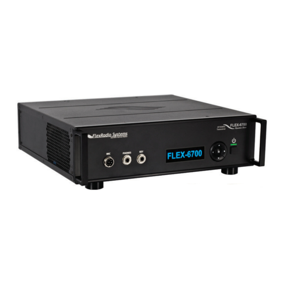
Page 20: Front Panel Controls And Connections
FLEX-6000 Signature Series – FLEX-6000 Hardware Reference Manual 6 FRONT PANEL CONTROLS AND CONNECTIONS 6.1 MICROPHONE JACK 6.1.1 Connector pinout Page 20 of 41 Copyright 2014 FlexRadio Systems. All Rights Reserved. -
Page 21: Supported Microphone Types
The multifunction indicator LED is above the power pushbutton. It indicates the condition of the radio hardware and software. 6.6.1 Chart for Indicator Color Codes SOLID BRIGHT RED: Transmitting on PA Page 21 of 41 Copyright 2014 FlexRadio Systems. All Rights Reserved. -
Page 22: If Optional Gpsdo Is Installed, There Are Additional Color Codes
This can take up to sixty seconds. It is advisable to allow the radio to shut down in this way. During a shutdown, the radio will save settings and so ending the shutdown early can cause a loss of settings. Page 22 of 41 Copyright 2014 FlexRadio Systems. All Rights Reserved. -
Page 23: Rear Panel Connections
FLEX-6000 Signature Series – FLEX-6000 Hardware Reference Manual 7 REAR PANEL CONNECTIONS Page 23 of 41 Copyright 2014 FlexRadio Systems. All Rights Reserved. -
Page 24: Dc Power Input
7.2 USB 2.0 PORTS The USB 2.0 ports are used to control peripheral devices that are connected to the radio. Refer to the SmartSDR documentation for information about how these work. Page 24 of 41 Copyright 2014 FlexRadio Systems. All Rights Reserved. -
Page 25: Powered Speakers
This input is a keying input for either CW or FSK. Refer to the SmartSDR documentation for information describing how to enable this input, and what configurations are available. Pin 4 is keyed to GROUND. Page 25 of 41 Copyright 2014 FlexRadio Systems. All Rights Reserved. -
Page 26: Pin 5, Pin 6, Pin 7, Pin 8 And Pin 10: Ground
The external signal is only sampled at initial startup of the radio software. It is necessary to make the external signal available on the rear panel connector before the radio is powered up. Otherwise, the signal will not be used. Page 26 of 41 Copyright 2014 FlexRadio Systems. All Rights Reserved. -
Page 27: Tx Relay Outputs [1,2,3]
This is the network connection for the radio. It is an auto-sensing 100 megabit or 1 gigabit Ethernet port. It auto-senses polarity as well, so if you are using a direct Page 27 of 41 Copyright 2014 FlexRadio Systems. All Rights Reserved. -
Page 28: Balanced Audio Input
There are a number of different definitions of “line level”. The audio input device in the FLEX-6000 series radios is designed for a “consumer line level” specification. This is defined as -10 dBV. If you plan to use “professional line level” devices to feed your radio, you will need to reduce the output level so that it does not exceed the -10 dBV level. -
Page 29: Tx Request Input (Interlock)
This female BNC connector is an output from the antenna feeding SCU-B. This signal is paired with RX ANT-B INPUT (Sec. 7.17). Refer to the SmartSDR documentation for information describing how this output is configured and how it can be used. Page 29 of 41 Copyright 2014 FlexRadio Systems. All Rights Reserved. -
Page 30: Chassis Ground
You will likely be using a PC and a DC power source so be sure to ground these devices together as well. Page 30 of 41 Copyright 2014 FlexRadio Systems. All Rights Reserved. -
Page 31: Installation
ESD threat that you aren’t used to: the Ethernet connection. Many times, adjacent ESD and lightning can enter a shack over the power, cable, or telephone lines. The ESD will then “jump” your Internet modem device and travel Page 31 of 41 Copyright 2014 FlexRadio Systems. All Rights Reserved. -
Page 32: Direct Pc Connection (Link-Local)
Please refer to the FLEX-6000 Quick Start Guide and SmartSDR Software User’s Guide for information regarding installation, configuration, and operation of your radio with this software. Page 32 of 41 Copyright 2014 FlexRadio Systems. All Rights Reserved. -
Page 33: Digital Mode Setup
Accessory connector is used to facilitate both the input and output audio connections to the PC sound card. A detailed schematic of the ACC connector’s audio connections can be found in the FLEX-6000 Hardware Reference Manual. Page 33 of 41 Copyright 2014 FlexRadio Systems. All Rights Reserved. - Page 34 When connecting the FLEX-6000 to a PC sound card, connect one of the FLEX-6000 inputs to the LINE OUT on the sound card and one of the FLEX-6000 outputs to the MIC or LINE IN on the sound card. Page 34 of 41 Copyright 2014 FlexRadio Systems. All Rights Reserved.
-
Page 35: Antenna Considerations
FLEX-6000 Signature Series – FLEX-6000 Hardware Reference Manual 10 ANTENNA CONSIDERATIONS The FLEX-6000 Series radios incorporate a unique smart antenna switching matrix to simplify connections from your radio to your station antennas. Below are the signal flow diagrams for the FLEX-6500 and FLEX-6700 transceivers: Page 35 of 41 Copyright 2014 FlexRadio Systems. -
Page 36: Antenna Selection
Using the antenna matrix, you can receive over a wide range, then use your tuned narrowband antennas for transmitting. Consult the SmartSDR Software User’s Guide for antenna configuration. Page 36 of 41 Copyright 2014 FlexRadio Systems. All Rights Reserved. -
Page 37: Optional Gps Disciplined Oscillator (Gpsdo) Setup
“locked” mode, the MSI will go to SOLID BLUE. Once locked, the GPSDO may re-synchronize occasionally due to satellite changes. A LONG FLASHING BLUE will indicate this “hold phase”. If GPS satellites are no longer visible, the GPSDO will enter Page 37 of 41 Copyright 2014 FlexRadio Systems. All Rights Reserved. - Page 38 Earth. This is normal and the radio is fully functional during this process. - GPSDO self-installation is possible and is covered in a separate manual included with the GPSDO OPTION KIT. Page 38 of 41 Copyright 2014 FlexRadio Systems. All Rights Reserved.
-
Page 39: Key Contacts
Email: sales@flexradio.com support@flexradio.com Community Support: http://community.flexradio.com FlexRadio Systems Representative for EU SDR-Funktechnik GmbH Godeke-Michels-Weg 12 D-21762 Otterndorf Germany Phone: (+49) 4751 900501 Fax: (+49) 4751 998569 Email: FlexRadio-EU@t-online.de www.flexradio.com Page 39 of 41 Copyright 2014 FlexRadio Systems. All Rights Reserved. -
Page 40: Regulatory Requirements
Directive on Electronic and electrical equipment (WEEE regulation) and will therefore not be disposed of with household waste. Dispose of the device at your local collection points for electronic equipment! Page 40 of 41 Copyright 2014 FlexRadio Systems. All Rights Reserved. - Page 41 WE THE UNDERSIGNED HEREBY DECLARE THAT THE EQUIPMENT SPECIFIED ABOVE CONFORM TO THE ABOVE STANDARDS. FlexRadio Systems Date of Testing: April 24, 2013 FlexRadio Systems, 4616 W. Howard Lane, Ste. 1-150, Austin, Texas 78728 U.S.A. Person Responsible: Gerald Youngblood (Signature on file) Page 41 of 41...
Need help?
Do you have a question about the FLEX-6000 Series and is the answer not in the manual?
Questions and answers