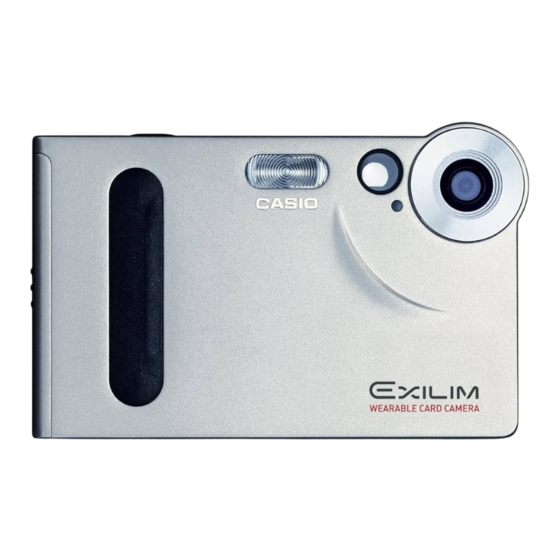
Casio EX-S1 Service Manual And Parts List

Casio digital camera service manual and parts list
Hide thumbs Also See for EX-S1:

Advertisement

(without price)
EX-S1/M1
JUN. 2002
EX-S1
EX-M1
Ver. 2
Oct/ 2002
INDEX
Ver.1
Jul/ 2002
R

Advertisement

Table of Contents
loading

Summary of Contents for Casio EX-S1

  • Page 1 (without price) EX-S1/M1 JUN. 2002 EX-S1 EX-M1 Ver. 2 Oct/ 2002 INDEX Ver.1 Jul/ 2002...
  • Page 2: Table Of Contents

    CONTENTS SPECIFICATIONS ............................1 TEST MODE ..............................4 PROGRAM VERSION UPGRADING ......................5 1. How to confirm the program version ..................... 5 2. How to upgrade the program ......................5 3. How to recover the program in case of the failure ............... 6 COLOR ADJUSTMENT ..........................
  • Page 3: Specifications

    SPECIFICATIONS Image Files Format Snapshots: JPEG (Exif Version 2.2); DCF (Design Rule for Camera File System)1.0 standard; DPOF compliant Movies: AVI (Motion JPEG) Audio: WAV (EX-M1 only) Recording Media 12MB built-in flash memory SD Memory Card MultiMedia Card Image Size Snapshots: 1600 x 1200pixels 1280 x 960pixels...
  • Page 4 Exposure Control Metering: Multi-pattern by imaging element Exposure: Program AE Exposure Compensation: –2EV to +2EV (in 1/3EV steps) Shutter CCD shutter, mechanical shutter 1/4 to 1/8000 second Aperture F2.5 fixed White Balance Automatic/fixed (4 modes) /Manual Self-timer 10 seconds Built-in Flash Flash Modes: Auto, Off, On, Red-eye reduction Approximate Flash Range:...
  • Page 5 Dimensions EX-S1: 88(W) x 55(H) x 11.3(D) mm (3.5˝(W) x 2.2˝(H) x 0.4˝(D)) (excluding projections) EX-M1: 88(W) x 55(H) x 12.4(D) mm (3.5˝(W) x 2.2˝(H) x 0.5˝(D)) (excluding projections) Weight EX-S1: Approximately 85 g (3.0 oz) (excluding battery and accessories) EX-M1: Approximately 87 g (3.1 oz)
  • Page 6: Test Mode

    While holding the camera in a horizontal position, press the set button twice towards your "RIGHT" and then press "MENU" . EX-S1 (as of May 28, 2002) EX-M1 (as of May 28, 2002) + + K X 8 5 1 + + + + K X 8 5 2 + + P R : 0 2 .
  • Page 7: Program Version Upgrading

    2. How to update the firmware 1. Prepare the memory card which contains the software for upgrading firmware in the root directory. EX-S1: ex-s1.bin EX-M1: ex-m1.bin 2. Insert the above memory card into the camera, and set a fully charged battery in the camera.
  • Page 8: How To Recover The Program In Case Of The Failure

    3. How to recover the program in case of the failure 1. Prepare the following firmware restoration program and change its name to "mercury.bin". EX-S1 : kx851r.hbn EX-M1 : kx852r.hbn • Insert the SD card into the computer using the PC card adaptor.
  • Page 9: Color Adjustment

    (VMEM manufactur's name)" can be found in "USB device for UUSBD", the computer has successfully recognised the driver. (12) The test driver can be used for both CASIO/PENTAX. Installing the test driver into either one enables the other one to recognise it.
  • Page 10 NOTE: How to uninstall the USB driver for the USB test mode • Connect the camera while in the USB test mode to the computer so that the computer recognises the camera. • Right-click "My computer", select "Property" and open "Device manager". •...
  • Page 11: Lens Replacement

    Make sure to backup ADJ DATA before replacing the MAIN PCB. IMPORTANT NOTICE: The MAIN PCB is a common part for EX-S1 and EX-M1 as a spare part. After replacing MAIN PCB, firm up and system initialization should be required.
  • Page 12: Vcom Dc Adjustment

    5 AE operation 6 Charging and cradle connection (USB function etc.) check 7 Appearance check 8 Buzzer check (EX-S1 only) 9 Recording with a microphone, speaker and earphone sound production, and remote controller operation check (EX-M1 only) 2. Current consumption test Current consumption (Vcc1 = 3.60 ±...
  • Page 13: Disassembly

    DISASSEMBLY NOTE : Here EX-M1 is used. 1. Remove the CARD, BATTERY and the JACK COVER. 2. Remove five screws. Screws Screws Screw 3. Remove the REAR CASE ASSY. — 11 —...
  • Page 14 4. Removing the LCD ASSY 1 Remove the hook from the MAIN PCB and slide the LCD ASSY. 2 Remove the CONNECTOR. 3 Remove the LCD ASSY. Connector NOTE: Fix the FPC to the CONNECTOR tightly when assembling. 5. Remove the FPC from the CONNECTOR and then remove the SW UNIT. Connector —...
  • Page 15 6. Removing the SUB PCB ASSY 1 Unsolder the five lead wires. 2 Remove the hook and then the SUB PCB ASSY. The SUB PCB is connected to the MAIN PCB by the CONNECTOR. Note in assembling *1 Position these four lead wires in the space between the MAIN PCB and the SUB PCB. *2 Make sure that this lead wire does not touch the battery spring.
  • Page 16 8. Removing the LENS UNIT 1 Remove the CONNECTOR. 2 Remove the LENS UNIT while taking care of the hook. Hook 9. Remove the MAIN PCB. 10. Remove the microphone (EX-M1 only). — 14 —...
  • Page 18: Parts List

    PARTS PRICE LIST EX-S1/M1 Parts Code Parts Name Specification Price Item Remarks Code EX-S1 EX-M1 10085205 LENS UNIT RJK503328*001V01TK 10085206 ASSY / FRONT CASE RJK502949*001V01TK 10084967 ASSY / FRONT CASE RJK502953*001V01TK 10085208 ASSY / REAR CASE RJK502892*001V01TK 10084968 ASSY / REAR CASE...
  • Page 19: Printed Circuit Boards

    PRINTED CIRCUIT BOARDS MAIN PCB TOP VIEW — 17 —...
  • Page 20 MAIN PCB BOTTOM VIEW — 18 —...
  • Page 21 SUB PCB TOP VIEW BOTTOM VIEW — 19 —...
  • Page 22: Schematic Diagrams

    SCHEMATIC DIAGRAMS MAIN PCB — 20 —...
  • Page 23 SUB PCB (EX-S1 only) — 21 —...
  • Page 24 SUB PCB (EX-M1 only) — 22 —...
  • Page 25 (2) The following items were changed. · PARTS LIST (page 16) Ver. 2 : Correction of page 4, 5, 6, 7, 8, 9, 10 and 16. CASIO TECHNO CO.,LTD. Overseas Service Division Nishi-Shinjuku Kimuraya Bldg. 1F 5-25, Nishi-Shinjuku 7-Chome Shinjuku-ku, Tokyo 160-0023, Japan...

This manual is also suitable for:

Ex-m1

Table of Contents