Rangemaster Classic Deluxe 100 Dual Fuel User's Manual & Installation Instructions
Hide thumbs
Also See for Classic Deluxe 100 Dual Fuel:
- User's manual & installation instructions (40 pages) ,
- User's manual & installation instructions (36 pages) ,
- User's manual & installation instructions (48 pages)

Related Manuals for Rangemaster Classic Deluxe 100 Dual Fuel


Summary of Contents for Rangemaster Classic Deluxe 100 Dual Fuel
-
Page 1: User Guide
Britain’s No.1 Range Cooker USER GUIDE & INSTALLATION INSTRUCTIONS Classic Deluxe 100 Dual Fuel... - Page 2 We offer cookware to work perfectly with all fuel types manufactured by Rangemaster, including induction hobs. You can be assured of functionality with style, as well as the quality and meticulous attention to detail you expect from the pioneers of range cooking.
-
Page 3: Table Of Contents
Cleaning Your Cooker Stick on Label Pressure Testing Hotplate Burners Circuit Diagram The Griddle Glide-out Grill 10. Technical Data Control Panel and Doors Ovens Refit in the reverse order. The Tall Oven Cleaning Table Classic Deluxe 100 Dual Fuel U110073-04B... -
Page 5: Before You Start
Before You Start... If you smell gas Your cooker should give you many years of trouble-free cooking if installed and operated correctly. It is important • DO NOT turn electric switches on or off. that you read this section before you start, particularly if you DO NOT smoke •... -
Page 6: Cooker Care
Accessible parts will become hot during use and will NEVER leave a chip pan unattended. Always heat fat retain heat even after you have stopped cooking. slowly, and watch as it heats. Deep fry pans should Keep babies and children away from the cooker and be only one third full of fat. -
Page 7: Cooker Overview
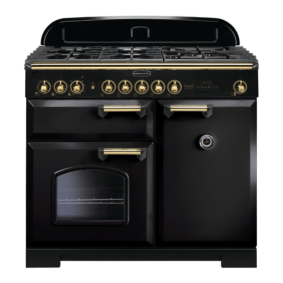
2. Cooker Overview Fig. 2.1 The 100 dual fuel cooker (Fig. 2.1) has the following features: Fig. 2.2 5 hotplate burners including a wok burner Control panel Glide-out grill Main multi-function oven Tall fan oven Hotplate Burners The drawing by each of the central knobs indicates which burner that knob controls. -
Page 8: Wok Burner
If, when you let go of the control knob, the burner goes out, Fig. 2.3 then the FSD has not been bypassed. Turn the control knob to the OFF position and wait for one minute before you try again, this time making sure to hold in the control knob for slightly longer. -
Page 9: The Wok Cradle
The Wok Cradle Fig. 2.9 The wok cradle is designed to fit a 35 cm wok. If you use a different wok, make sure that it fits the cradle. Woks vary very widely in size and shape. It is important that the wok sits down on the pan support –... -
Page 10: The Glide-Out Grill
The Glide-out Grill Fig. 2.15 Open the door and pull the grill pan carriage forward using the handle (Fig. 2.15). The grill has two elements that allow either the whole area of the pan to be heated or just the right-hand half. Adjust the heat to suit by turning the knob. - Page 11 The multi-function ovens have many varied uses. We suggest Fan Assisted Oven you keep a careful eye on your cooking until you are familiar This function operates the fan, circulating air heated with each function. Remember – not all functions will be by the elements at the top and the base of the oven.
-
Page 12: Operating The Ovens
Large items, such as whole chickens and joints should not be Fig. 2.18 defrosted in this way. We recommend this be carried out in a refrigerator. ArtNo.235-0003 - Classic DL MF knobs Defrosting should not be carried out in a warm oven or when an adjoining oven is in use or still warm. - Page 13 Minute Minder Fig. 2.21 Press and hold the [ ] button (Fig. 2.23), and then press the [+] button until the length of time you want to cook for is shown (Fig. 2.24). You can check the time remaining by pressing [ ].
- Page 14 Key Lock Fig. 2.31 Fig. 2.32 When the key lock is activated, the left-hand oven is locked and will not come on. To activate the key lock ArtNo.302-0009 - Activating Make sure that the clock is in manual mode and cancel any ArtNo.302-0008 - the key lock 2 active programs.
-
Page 15: Accessories
Accessories Fig. 2.36 Flat shelf Oven Shelves – Left-hand (Main) Oven Shelf guard In addition to the flat shelves, your cooker is supplied with a drop shelf (Fig. 2.36). The drop shelf increases the possibilities for oven shelf spacing. Front The oven shelves can be easily removed and refitted. -
Page 16: Cooking Tips
3. Cooking Tips Tips on Cooking with the Timer General Oven Tips If you want to cook more than one dish, choose dishes that The wire shelves should always be pushed firmly to the back require approximately the same cooking time. However, of the oven. -
Page 17: Cooking Table
4. Cooking Table DocNo.031-0004 - Cooking table - electric & fan single cavity The oven control settings and cooking times given in the table below are intended to be used Top (T) AS A GUIDE ONLY. Individual tastes may require the temperature to be altered to provide a ArtNo.050-0007 preferred result. -
Page 18: Cleaning Your Cooker
5. Cleaning Your Cooker Isolate the electricity supply before carrying out any Fig. 5.1 thorough cleaning. Allow the cooker to cool. NEVER use paint solvents, washing soda, caustic cleaners, biological powders, bleach, chlorine based bleach cleaners, coarse abrasives or salt. DO NOT mix different cleaning products –... -
Page 19: The Griddle
The Griddle Fig. 5.5 Always clean the griddle after use. Allow it to cool completely before removing. Immerse the griddle plate in hot soapy water. Use a soft cloth or, for stubborn stains, a nylon washing up brush. Note: If the griddle is washed in a dishwasher then some dishwasher residue may appear on the back. -
Page 20: Ovens
Glass Fronted Door Panels Fig. 5.10 The oven door front panels can be taken off so that the glass panels can be cleaned. Move the cooker forward to gain access to the sides (see the ‘Moving the Cooker’ section under ‘Installation’). -
Page 21: Cleaning Table
Cleaning Table Cleaners listed (Table 5.1) are available from supermarkets or electrical retailers as stated. For enamelled surfaces use a cleaner that is approved for use on vitreous enamel. Regular cleaning is recommended. For easier cleaning, wipe up any spillages immediately. Hotplate Part Finish... -
Page 22: Troubleshooting
6. Troubleshooting Hotplate ignition or hotplate burners faulty If there is an installation problem and I don’t get my original installer to come back to fix it who pays? Is the power on? Is the clock illuminated? You do. Service organizations will charge for their call If not, there maybe something wrong with the power outs if they are correcting work carried out by your supply. - Page 23 The timed oven is not coming on when automatic cooking Fig. 6.1 Has the oven knob been left in the OFF position by mistake? Is the oven locked (see above)? ArtNo.324-0005 Oven light bulb Oven temperature getting hotter as the cooker gets older If turning the temperature down using the oven control knob has not worked, or has only worked for a short time, then you may need a new thermostat.
-
Page 24: Installation
INSTALLATION Check the appliance is electrically safe and gas sound when you have finished. 7. Installation Dear Installer In the UK the cooker must be installed in accordance with: Before you start your installation, please complete the details below, so that, if your customer has a problem relating to •... -
Page 25: Location Of Cooker
INSTALLATION Check the appliance is electrically safe and gas sound when you have finished. Location of Cooker Checking the Parts: The cooker may be installed in a kitchen/kitchen diner but 3 pan supports Griddle NOT in a room containing a bath or shower. This appliance is designed for domestic cooking only. -
Page 26: Positioning The Cooker
INSTALLATION Check the appliance is electrically safe and gas sound when you have finished. Positioning the Cooker Fig. 7.1 ArtNo.090-0009 - 90 2BC cooker min spacings Fig. 7.1 and Fig. 7.2 show the minimum recommended distance from the cooker to nearby surfaces. 75 mm 75 mm 650 mm... -
Page 27: Completing The Move
INSTALLATION Check the appliance is electrically safe and gas sound when you have finished. Lowering the Two Rear Rollers Fig. 7.5 To adjust the height of the rear of the cooker, first fit a 13 mm spanner or socket wrench onto the hexagonal adjusting nut (Fig. -
Page 28: Repositioning The Cooker Following Connection
INSTALLATION Check the appliance is electrically safe and gas sound when you have finished. Repositioning the Cooker Following Fig. 7.10 Connection If you need to move the cooker once it has been connected then you need to unplug it and, having gripped under the fascia panel and lifted the front of the cooker slightly (Fig. -
Page 29: Gas Connection
INSTALLATION Check the appliance is electrically safe and gas sound when you have finished. Gas Connection Fig. 7.12 This must be in accordance with the relevant standards. The flexible hose (not supplied with the cooker) must be in accordance with the relevant standards. Hoses may be Gas inlet purchased at most builders’... -
Page 30: Electrical Connection
INSTALLATION Check the appliance is electrically safe and gas sound when you have finished. Electrical Connection Fig. 7.13 The cooker must be installed by a qualified electrician, in accordance with all relevant British Standards/Codes of Practice (in particular BS 7671), or with the relevant national and local regulations. -
Page 31: Conversion To Lp Gas
WARNING – SERVICING TO BE CARRIED OUT ONLY BY AN AUTHORISED PERSON Disconnect from electricity and gas before servicing. Check appliance is safe when you have finished. 8. Conversion to LP Gas Check the ‘Technical Data’ section at the back of the book Fig. -
Page 32: Pressure Testing
WARNING – SERVICING TO BE CARRIED OUT ONLY BY AN AUTHORISED PERSON Disconnect from electricity and gas before servicing. Check appliance is safe when you have finished. Pressure Testing Connect the appliance to the gas supply. The gas pressure can be measured at one of the hotplate burner jets (not a wok burner). -
Page 33: Circuit Diagram
9. Circuit Diagram P038434 P095199 w br The connections shown in the circuit diagram are for single-phase. The ratings are for 230 V 50 Hz. Code Description Code Description Code Colour Grill energy regulator Right-hand fan oven thermostat Blue Grill element left-hand side Right-hand fan oven control switch Brown Grill element right-hand side... -
Page 34: Technical Data
10. Technical Data THE COOKER IS CATEGORY: CatII 2H3+. It is supplied set for group H natural gas. A conversion kit from NG to LP is available for the cooker. INSTALLER: Please leave these instructions with the user. DATA BADGE LOCATION: Cooker back, serial number repeater badge below oven door opening. COUNTRY OF DESTINATION: GB, IE, FR, NL, DE, SE, AT, BE, CH, LU, IT. - Page 35 0800 804 6261 or depending on your mobile network tariff you can call free on 0370 789 5107. For a competitive quote and to arrange for a Rangemaster approved engineer to attend, call Consumer Services on: 0800 804 6261 or...
- Page 36 Registered in England and Wales. Registration No. 354715 Registered Office: Juno Drive, Leamington Spa, Warwickshire, CV31 3RG Rangemaster continuously seeks improvements in specification, design and production of products and thus, alterations take place peri- odically. Whilst every effort is made to produce up-to-date literature, this booklet should not be regarded as an infallible guide to current...
Need help?
Do you have a question about the Classic Deluxe 100 Dual Fuel and is the answer not in the manual?
Questions and answers