Harman PB105 Owner's Manual
Pellet boiler
Hide thumbs
Also See for PB105:
- Installation and operating manual (49 pages) ,
- Installation & operating manual (40 pages) ,
- Installation & operating manual (48 pages)
Table of Contents
Advertisement
Owner's Manual
MOdel:
PB105 Pellet Boiler
Contact your local dealer with questions
on installation, operation or service.
• Important operating and
maintenance instructions
included.
Please read this entire manual before
installation and use of this pellet fuel-
burning room heater.
Failure to follow these instructions could
result in property damage, bodily injury
or even death.
• Do not store or use gasoline or other flammable vapors
and liquids in the vicinity of this or any other appliance.
• Do not overfire - If any external part starts to glow, you
are overfiring. Reduce feed rate. Overfiring will void
your warranty.
• Comply with all minimum clearances to combustibles
as specified. Failure to comply may cause house fire.
!
Tested and approved for wood pellets and shelled field
corn fuel only. Burning of any other type of fuel voids
your warranty.
!
Check building codes prior to installation.
• Installation MUST comply with local, regional, state and
national codes and regulations.
• Contact local building or fire officials about restrictions
and installation inspection requirements in your area.
www.harmanstove.com
dO NOT dISCARd THIS MANUAl
• Read, understand and
follow these instructions
for safe installation and
operation.
WARNING
CAUTION
CAUTION
NOTICe
• Leave this manual with
party responsible for use
and operation.
Hot glass will cause burns.
• Do not touch glass until it is cooled
• NEVER allow children to touch glass
• Keep children away
• CAREFULLY SUPERVISE children in same room as
fireplace.
• Alert children and adults to hazards of high temperatures.
High temperatures may ignite clothing or other
flammable materials.
• Keep clothing, furniture, draperies and other flammable
materials away.
To obtain a French translation of this manual, please
contact your dealer or visit www.harmanstoves.com
Pour obtenir une traduction française de ce manuel, s'il
vous plaît contacter votre revendeur ou visitez www.
harmanstoves.com
WARNING
HOT SURFACeS!
Glass and other surfaces are hot
during operation AND cool down.
NOTe
3-90-07205R26_10/14
Advertisement
Table of Contents

Related Manuals for Harman PB105


Summary of Contents for Harman PB105
- Page 1 Owner’s Manual MOdel: PB105 Pellet Boiler Contact your local dealer with questions on installation, operation or service. NOTICe dO NOT dISCARd THIS MANUAl • Read, understand and • Leave this manual with • Important operating and follow these instructions party responsible for use maintenance instructions for safe installation and and operation. included. operation. WARNING WARNING Please read this entire manual before HOT SURFACeS! installation and use of this pellet fuel- burning room heater.
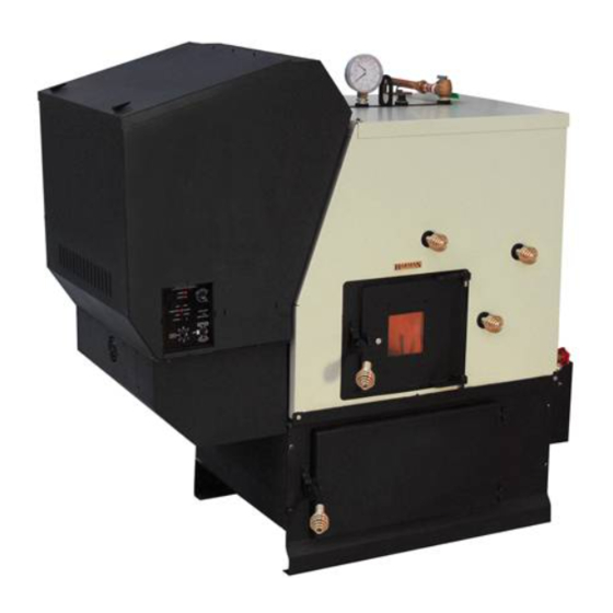
- Page 2 Parts locations 1-1/4” FMPT Supply Temperature / Pressure Gauge Hopper Lid Aquastat Well Latches Pressure Relief Valve Blank Cover (Re- moved w/ Domestic Hot Water Option Hopper Cleaning Rods Control Board 1-1/4” FMPT Return Control Board Cover Vent Pipe Access Cover to Hopper / Swing Plate Knob Firebox Door...
-
Page 3: Table Of Contents
Table of Contents Product Specific and Important Safety Information ..4 Atmospheric Conversion ..... . . 37 Warranty ........5-6 Optional Domestic Hot Water Coil . -
Page 4: Product Specific And Important Safety Information
Product Specific and Important Safety Information Appliance Certification: Model: Pellet Burning Boiler - PB105 Test lab: Omni-Test Laboratories, Inc. Report #: 135-S-16-6 Please read this entire manual before you install and use Type: Pellet Fueled Central/Supplementary For Residential your new boiler. Failure to follow instructions may result in property damage, bodily injury, or even death. Standard(s): CAN/CSA B366.1-M91, and UL 391 SAVE THESE INSTRUCTIONS Note: This appliance is also approved for installation into a shop. Hearth & Home Technologies 352 Mountain House Road Harman Central Heating Appliances are built and ® Halifax, PA 17032 tested to be complete Home Heating solutions. As with... -
Page 5: Warranty
Warranty Hearth & Home Technologies lIMITed lIFeTIMe WARRANTY Hearth & Home Technologies, on behalf of its hearth brands (”HHT”), extends the following warranty for HHT gas, wood, pellet, coal and electric hearth appliances that are purchased from an HHT authorized dealer. WARRANTY COVeRAGe: HHT warrants to the original owner of the HHT appliance at the site of installation, and to any transferee taking ownership of the appliance at the site of installation within two years following the date of original purchase, that the HHT appliance will be free from defects in materials and workmanship at the time of manufacture. After installation, if covered compo- nents manufactured by HHT are found to be defective in materials or workmanship during the applicable warranty period, HHT will, at its option, repair or replace the covered components. HHT, at its own discretion, may fully discharge all of its obligations under such warranties by replacing the product itself or refunding the verified purchase price of the product itself. The maximum amount recoverable under this warranty is limited to the purchase price of the product. This warranty is subject to conditions, exclusions and limitations as described below. WARRANTY PeRIOd: Warranty coverage begins on the date of original purchase. In the case of new home construction, warranty coverage begins on the date of first occupancy of the dwelling or six months after the sale of the product by an independent, authorized HHT dealer/ distributor, whichever occurs earlier. The warranty shall commence no later than 24 months following the date of product shipment from HHT, regardless of the installation or occupancy date. The warranty period for parts and labor for covered components is produced in the following table. The term “Limited Lifetime” in the table below is defined as: 20 years from the beginning date of warranty coverage for gas appliances, and 10 years from the beginning date of warranty coverage for wood, pellet, and coal appliances. These time periods reflect the minimum expected useful lives of the designated components under normal operating conditions. Warranty Period HHT Manufactured Appliances and Venting Components Covered Parts Labor Wood Pellet Coal Electric Venting Wood All parts and material except as covered by Conditions,... -
Page 6: Warranty
Warranty WARRANTY CONdITIONS: • This warranty only covers HHT appliances that are purchased through an HHT authorized dealer or distributor. A list of HHT authorized dealers is available on the HHT branded websites. • This warranty is only valid while the HHT appliance remains at the site of original installation. • This warranty is only valid in the country in which the HHT authorized dealer or distributor that sold the appliance resides. • Contact your installing dealer for warranty service. If the installing dealer is unable to provide necessary parts, contact the nearest HHT authorized dealer or supplier. Additional service fees may apply if you are seeking warranty service from a dealer other than the dealer from whom you originally purchased the product. • Check with your dealer in advance for any costs to you when arranging a warranty call. Travel and shipping charges for parts are not covered by this warranty. WARRANTY eXClUSIONS: This warranty does not cover the following: • Changes in surface finishes as a result of normal use. As a heating appliance, some changes in color of interior and exterior surface finishes may occur. This is not a flaw and is not covered under warranty. • Damage to printed, plated, or enameled surfaces caused by fingerprints, accidents, misuse, scratches, melted items, or other external sources and residues left on the plated surfaces from the use of abrasive cleaners or polishes. • Repair or replacement of parts that are subject to normal wear and tear during the warranty period. These parts include: paint, wood, pellet and coal gaskets, firebricks, grates, flame guides, batteries and the discoloration of glass. • Minor expansion, contraction, or movement of certain parts causing noise. These conditions are normal and com- plaints related to this noise are not covered by this warranty. • Damages resulting from: (1) failure to install, operate, or maintain the appliance in accordance with the installation instructions, operating instructions, and listing agent identification label furnished with the appliance; (2) failure to install the appliance in accordance with local building codes; (3) shipping or improper handling; (4) improper opera- tion, abuse, misuse, continued operation with damaged, corroded or failed components, accident, or improperly/ incorrectly performed repairs; (5) environmental conditions, inadequate ventilation, negative pressure, or drafting caused by tightly sealed constructions, insufficient make-up air supply, or handling devices such as exhaust fans or forced air furnaces or other such causes; (6) use of fuels other than those specified in the operating instructions; (7) installation or use of components not supplied with the appliance or any other components not expressly authorized and approved by HHT; (8) modification of the appliance not expressly authorized and approved by HHT in writing;... -
Page 7: Assembly
Assembly Boiler Kit Materials: (Refer to “Parts Locations” section Installation of the Flue Tunnel Weldment, Combustion in this manual) Blower and Wiring, eSP and Heat Shield: List of items contained within the boiler kit shipped with the Step 1: First install the flue tunnel weldment by aligning the unit. (4) studs with the (4) holes in the ash chamber base. Fasten 1 - Control board cover the (4) nuts and lock washers provided, to the studs by 1 - Access cover (Hopper Swing Plate Knob) removing the access cover on the secondary ash chamber. - Page 8 Assembly Refer to the illustration under “Parts Locations” in this MINIMUM NON-COMBUSTIBLE FLOOR PROTECTION AREA manual to identify the components listed below: 1. Install the control board cover as well as the access cover located on the feeder cover. NON-COMBUSTIBLE 2. Install the spring handles provided with the unit on FLOOR PROTECTOR the ash door, firebox door and the heat exchanger cleanout rod handles. (Fasten handles by turning them counterclockwise and pushing inward simultaneously).
-
Page 9: Assembly
Assembly 80” TOP VIEW 6” 18” 20” FRONT VIEW Notes: A. Manufacturer recommended minimum clearance. B. Minimum clearance to combustibles BUT NOT RECOMMENDED! (See Note C). C. Mfr’s recommendation to allow for full opening of feeder swing plate = 16.5” D. Minimum clearance to allow servicing of combustion blower = 20” E. Minimum clearance to combustibles = 36” F. Pellet vent clearance to combustibles = 1” G. Stove top to ceiling = 22.5” H. Minimum ceiling height or alcove height = 66” I. Maximum alcove depth = 80” INSTAllATION IS TO Be PeRFORMed BY A NOTe: All installation clearances and restrictions QUAlIFIed INSTAlleR. must be adhered to. NOTe: Use only 4”... -
Page 10: Venting
Venting Requirements for Terminating the Venting I. The clearance to service regulator vent outlet must be a WARNING: Venting terminals must not be recessed into a minimum of 6 feet. wall or siding. J. The clearance to a non-mechanical air supply inlet to the NOTE: Only PL vent pipe wall pass-throughs and fire stops building or the combustion air inlet to any other appliance should be used when venting through combustible materials. must be a minimum of 48”. NOTE: Always take into consideration the effect the K. The clearance to a mechanical air supply inlet must be a prevailing wind direction or other wind currents will cause minimum of 10 feet. with flyash and /or smoke when placing the termination. L. The clearance above a paved sidewalk or a paved In addition, the following must be observed: driveway located on public property must be a minimum of 7 feet. - Page 11 Venting 30 Ft Altitude in thousands of feet. 25 Ft 20 Ft 15 Ft 12 Ft 10 Ft 10 Ft 7 Ft 5 Ft 5 Ft 5 Ft 0 Ft 0 Ft 0 Ft Total Lineal Feet combined should not exceed Note: The total Lineal Feet decreases as the 30 Feet.
- Page 12 Venting Venting This is the minimum venting configuration. Use 4” pellet vent pipe only. A combustion blower is used to extract the combustion gases from the firebox. This creates a negative pressure in the firebox and a positive pressure in the venting system as shown in Fig. 4. The longer the vent pipe and more elbows used in the system, the greater the flow resistance. Because of these facts we recommend using as few elbows as possible 4” Type “L” or and 30 feet or less of vent pipe. The maximum horizontal run “PL” Vent pipe should not exceed 18 feet. Be sure to use wall and ceiling pass through fittings (which are approved for pellet vent pipe ) when going through combustible materials.
- Page 13 Venting Installation NOTe: Use only 4” diameter approved pellet venting system. Be sure to inspect and clean exhaust venting system frequently. INSTAllATION IS TO Be PeRFORMed BY A QUAlIFIed INSTAlleR. dO NOT INSTAll A FlUe dAMPeR IN THe eXHAUST VeNTING SYSTeM OF THIS UNIT. dO NOT CONNeCT THIS UNIT TO A CHIMNeY FlUe SeRVING ANOTHeR APPlIANCe.
-
Page 14: Outside Air Installation
Outside Air Installation Outside Air To install outside air, use 3” galvanized steel flex pipe. Fig. 6. There is a break-away hole on the rear panel which must be removed before connecting the flex pipe. See Fig. 7. When the appliance is side wall vented: The air intake is best located on the same exterior wall as the exhaust vent outlet, and located lower on the wall than the vent outlet. When the appliance is roof vented: The air intake is best located on the exterior wall oriented toward the prevailing Termination Cap part# 1-10-09542 wind direction during the heating season. Fig. 6 Never terminate the outside air above the vent pipe outlet. The maximum length of this pipe is 20 feet. Termination Cap part number 1-10-09542 should be used to keep birds, rodents etc. out of the inlet pipe. See Fig. 6. -
Page 15: Main Wiring Harness
Main Wiring Installation To install power to the boiler, first remove the cover on the 4” X 4” junction box located on the back of the unit. There are several knockout holes provided for the incoming main power wires. Also, a knockout hole can be used for the auxiliary output overheat zone (if used). The minimum recommended circuit is 6 AMP - 120 VAC - 60 HZ. This boiler should be the only appliance on the circuit. This boiler should never be powered by the use of an extension cord. The recommended high and low voltages are, 130 VAC 60 Hz maximum high voltage, and 113 VAC 60 Hz minimum low voltage. The furnace will continue to operate at voltages as low as 105 VAC , although it can not be guaranteed that automatic ignition will occur. NOTe: If other sources of electrical power are to be used ( such as a generator ) for normal operation or emergency operation, this source should be checked before installation. -
Page 16: Plumbing Installations
Plumbing Installation 3/4” NOTe: Cold return water temperature (Sustained temperatures below 140° F) will lead to condensation in the firebox. This moisture can lead to creosote formation. To help minimize moisture and creosote, it is strongly recommended that some form of temperature balance is incorporated into the return water system. NOTICe: When installing with the atmospheric conversion: All of the pressurized system components shown are not necessary. Air vents or bleeders will need to be removed from the plumbing system to prevent air from entering the lines. Control dipswitch #6 will need to be turned “ON”. 3/4” 3-90-07205R26_10/14... - Page 17 Plumbing Installation Boilers intended to be connected to an existing boiler or boiler system shall: 1. Be capable of being installed without interfering with the normal delivery of heated water from the original boiler to the radiation system. 2. Be capable of being installed to operate as intended without affecting the operation of the electrical and mechanical safety controls of the original boiler. 3. Provide, upon completion of the installation, for a change over from one fuel to the other without requiring the manual adjustment of any controls or components other than the thermostats. 4. Be compatible with the operation of a service water-heating coil within the original boiler without bypassing the operation of the solid-fuel boiler. 5. Have provision for preventing, or adequate water capacity within the boiler to prevent, damage to the boiler from loss of circulation due to electrical power failure. 6. Be capable of being installed without changing the function of the control or rewiring of the original boiler. A wiring interconnection is permitted. The electrical system of both boilers shall be powered from a single branch circuit without exception. (CAN/CSA- B366.1-M91) 7. Pertaining to CAN/CSA- B365-01, Have a clearly labelled device, located at each entrance to the boiler area, which can be thrown to discontinue operation of the feed system. NOTICE: When installing with the atmospheric conversion: All of the pressurized system components shown are not necessary.
- Page 18 Plumbing Installation EXAMPLE OF TYPICAL TANKLESS DOMESTIC HOT WATER PIPING HIGH TEMPERATURE TEMPERED HOT WATER TO WATER (IF NEEDED) SHOWERS AND FAUCETS NOTE: ALWAYS REFER TO THE INDIVIDUAL COMPONENTS OPTIONAL DOMESTIC RECOMMENDED INSTALLATION INSTRUCTIONS FOR THE PROPER HOT WATER COIL MOUNTING POSITION AND LOCATION WITHIN THE PIPING SYSTEM.
- Page 19 Plumbing Installation NOTE: ALWAYS REFER TO THE INDIVIDUAL COMPONENTS RECOMMENDED TYPICAL BOILER HOT WATER PIPING SHOWING AIR REMOVAL SYSTEM, PROVISIONS FOR THE EXPANSION OF INSTALLATION INSTRUCTIONS FOR THE PROPER MOUNTING POSITION WATER AND THE AUTOMATIC COLD WATER SUPPLY. ALSO SHOWN IS THE AUTOMATIC MIXING VALVE. THIS AND LOCATION WITHIN THE PIPING SYSTEM.
-
Page 20: Plumbing Installations
Plumbing Installation NOTE: ALWAYS REFER TO THE INDIVIDUAL COMPONENTS RECOMMENDED EXAMPLE OF A TYPICAL MULTI-ZONE HEATING SYSTEM WITH A SINGLE INSTALLATION INSTRUCTIONS FOR THE PROPER MOUNTING POSITION AND CIRCULATOR AND INDIVIDUAL ZONE VALVES LOCATION WITHIN THE PIPING SYSTEM. AIR VENT (TYPICALLY INSTALLED IN THE HIGHEST ACCESSABLE LOCATION IN THE PIPING) AIR VENT FROM ADDITIONAL ZONES... -
Page 21: Overheat Safety Zone
Over Heat Safety Zone Overheat Safety Zone (dump Zone): STRONGlY ReCOMMeNded in all installations. When the pellet boiler is operating at High burn, and all demand from the heating system stops, the control will reduce the feed rate and shut down completely as necessary. This may take several minutes, and the remaining heat may cause the water temperature to continue to rise. If the temperature gets too high, the OVERHEAT SAFETY ZONE light on the control will illuminate, and the DARK BLUE circuit in the junction box is energized(see wiring diagram). This circuit will flow 120V to operate a circulator pump installed to flow to the overheat dump zone established in the original installation plan. If opening a zone valve is the chosen method of dumping the excess heat, a voltage reduction relay will most likely be needed. If the water temperature continues to rise to the risk of boiling point, the feed system will stop and the boiler will shut-down. A manual reset will then be required to operate the boiler. Without a dump zone in place, the excess temperature could build pressure to the point of opening the relief valve, or with the atmospheric conversion it may allow the water to boil and exit through the over-flow of the atmospheric tank. Both scenarios may create water damage and/or a slip hazard. The boiling temperature of water varies at different altitudes and atmospheric pressures. Therefore, at elevations above 3000 feet, and when using the atmospheric conversion, circuit board dipswitch #6 must be in the “ON” position. Power Failure / Heat dissipation loop EXAMPLE OF PIPING IN ACCORDANCE WITH (CAN/CSA-B366.1) A POWER FAILURE HEAT DISSIPATION LOOP BALANCING SYSTEM SUPPLY VALVE... -
Page 22: Low Water Cut-Off Control Tip Connection (Lwco)
Low water cut-off control LWCO Wiring Instructions TO BE UsEd whERE REqUiREd By LOCaL COdEs Read and follow the instructions provided with the specific LWCO Control selected. The LWCO Control will provide a set of contacts that are closed when water is present at the sensor. It will open the feed motor circuit when a low water condition exist. Depending on the model selected, a manual reset of the control may be required after a low water condition has existed. • waRNiNg: To prevent electrical shock or equipment damage, make sure power is turned off to the boiler. • Locate the black wire from the wiring harness that connects to the feed motor. Fig. 1 • Separate the black wires at the ¼” push on connectors for the feed motor. Fig. 2 & Fig. 3 • The male connector will be on the wiring harness and the female connector will be on the feed motor wire. Fig. 3 &... -
Page 23: Draft Test Procedure
draft Test Procedure After the venting is completed, the firebox low draft will need Firebox Door to be checked and possibly adjusted. After removing the 3/8” bolt from the draft hole shown in Fig. 9, insert the draft meter tube. The appliance doors and hopper lid must be latched Draft Bolt Air Wash during this test. (It is recommended that the draft meter have Location Slot a scale of 0 to 1” WC.) Turn the feed adjuster to “Test”. this will start the combustion blower and allow you to check and record the High Draft ______ - IWC date _______ The maximum draft must not exceed -.85” W.C. Some form of vent restrictor may be needed. (There is no control board adjustment for the High Draft) -
Page 24: Fuel Specifications
Fuel Specifications Fuel and Fuel Storage Performance Pellet fuel quality can fluctuate from manufacturer to • Higher ash content requires more frequent maintenance. manufacturer, and even from bag to bag. • “Premium” grade pellets will produce the highest heat Hearth & Home Technologies recommends using only fuel output. that is certified by the Pellet Fuels Institute (PFI). • Burning pellets longer than 1-1/2 inches (38mm) can cause inconsistent feeding and/or ignition. Fuel Material • Made from sawdust and/or other wood by-products We recommend that you buy fuel in multi-ton lots whenever • Source material typically determines ash content possible. However, we do recommend trying different brands prior to purchasing multi-ton lots, to ensure your Higher Ash Content Material satisfaction. -
Page 25: Esp Control
eSP Control Power Light Feed adjuster Indicates power to the control Sets the maximum feed rate board. Test Combustion blower, feed motor Status Light and safety dump zone are fully Will be lit anytime there is a call energized for the first minute. for heat. -
Page 26: Outdoor Air Reset Operation
Outdoor Air Reset Operation 3-90-07205R26_10/14... -
Page 27: Control Board Operation
Control Board Operation Setting the Boiler Temperature without the Outdoor air Temperature sensor installed To set the maximum boiler water temperature, simply turn the MAX. TEMP. dial to the desired setting. The control and the boiler will then perform to achieve and maintain the set temperature The MIN. TEMP. Knob is the boiler water temperature minimum, or the lowest temperature the water will go before the unit re-starts. Turning the knob fully counter-clockwise is the “OFF” position, while turning the knob clockwise, past the 140° marking, is the “ON” position.. with The Outdoor air Temp - sensor installed Maximum boiler temp setting is as described above. The MIN. TEMP. knob in addition to being the mode setting (on or off) now also has the function of setting the minimum boiler water temperature. This would be the lowest boiler... -
Page 28: Automatic Ignition
Automatic Ignition Starting A Fire Automatically 1. MIN. TeMP. Selector to “OFF”. This resets the control in addition to turning it off. 2. Clean Burnpot with scraper, if necessary. This is usually a weekly maintenance procedure. Cleaning the burn pot with the scraper with a small amount of new fuel in the bottom is not a problem. First, scrape the ashes on the front of the burn pot into the ash pan. Then scrape the hole grid surface downward into the burn pot. When the stove is ignited these scrapings will be pushed out by the feeder. The illustration at left shows the hopper swing plate open for easy access to the burn pot. The burn pot can also be reached through the firebox door. NOTE: To minimize the amount of stress placed on the hopper swing plate hinges, opening of the hopper swing plate should be done with the least amount of fuel in the hopper as possible. - Page 29 Automatic Ignition (Cont.) WARNING Fire Hazard. Keep combustible materials, gasoline and other flammable vapors and liquids clear of appliance. • Do NOT store flammable materials in the appliance’s vicinity. • NEVER USE GASOLINE, GASOLINE-TYPE LANTERN FUEL, KEROSENE, CHARCOAL LIGHTER FLUID, OR SIMILAR LIQUIDS TO START OR “FRESHEN UP” A FIRE IN THIS HEATER. KEEP ALL SUCH LIQUIDS WELL AWAY FROM THE HEATER WHILE IT IS IN USE. 8. Turn the MIN. TeMP. dial on the control board to the desired Minimum temperature. This will start the lighting • DO NOT BURN GARBAGE OR FLAMMABLE FLUIDS process if the temperature at the aquastat sensor is SUCH AS GASOLINE, NAPHTHA OR ENGINE OIL.
-
Page 30: Manual Ignition
Manual Ignition lighting a Fire Manually 4. Have matches or other ignition source ready. 5. Turn Mode Selector to desired MIN. TEMP. setting. This Lighting the fire manually will not be necessary unless the will start the combustion blower and allow the ESP to igniter system fails. control the fire in relation to the MAX. TEMP. Dial setting. Follow steps 1 through 5 of the instructions for automatic (The MAX. TEMP. dial setting must always be set above lighting. - Page 31 Manual Ignition (Cont.) 6. Apply starting gel as shown in Fig. 15 CAUTION A vapor flash could occur if too much time is allowed to pass before lighting the starting gel. CAUTION Care must be taken not to get starting gel on your hands or clothing. Serious burns could occur during the lighting 7. light the Starting Gel With A Match. process. 8. Close the doors the fire will light and the control will CAUTION adjust the fire to the proper level according to the MAX.
-
Page 32: Maintenance
Burnpot Maintenance Use the flat end of the scraper provided to scrape down over the holed surface of the burnpot grate. Fig. 18. It is not necessary to clean out the scrapings from this cleaning because they will be pushed out the next time the auger operates. Note: Make a special effort to scrape the bottom inside corners of the burnpot where the auger tube enters the burnpot. -
Page 33: Ash Removal And Disposal
Ash Removal Ash Door Ash Door Handle Ash Pan Ash Pan Handle Fig. 21 disposal of ashes WARNING Ashes should be placed in a steel container with a tight fitting lid. The closed container of ashes should be moved outdoors immediately and placed on a non-combustible floor or on the RISK OF FIRe! ground, well away from all combustible materials, pending • Ash, soot or creosote build-up may cause final disposal. If ashes are disposed of by burial in soil or overheating or fire. otherwise locally dispersed, they should be retained in the • Routine cleaning of heat exchangers and venting closed container until all cinders have thoroughly cooled. -
Page 34: Firebox Maintenance
Firebox Maintenance Heat Exchanger Cleanout Rod Handles Firebox Door Heat Exchanger Tube Secondary Ash Chamber Access Plate Fines Cleanout Cover Firebox Wall Ash Door Cleaning 2. Open firebox door and vacuum ash from ledges and ash This cleaning should be done after each ton of pellets used. deflector. You can also clean the firebox door viewing The frequency of this cleaning will be directly related to the glass using a typical glass cleaner and soft cloth. quality and the ash content of the pellets being used. Keep 3. Open the ash door and remove the ash pan. Dispose of in mind that the cleaner the heat exchanger surface is kept, any ash that has accumulated in the ash pan as well as... -
Page 35: Combustion Blower Maintenance
Combustion Blower/Heat exchanger Maintenance The boiler MUST be OFF and COOl before you should attempt to clean the combustion blower. The wire to the combustion blower doesn’t need to be disconnected during the cleaning process. Loosen the three (3) thumb screws about 4 turns each. See Fig. 23. Hold the motor head with one hand and the blower plate handle with the other hand. Pull outward on the plate handle until the complete unit comes loose. Now rotate the plate counter-clockwise about 1/8 turn. This will allow the Heat Shield complete assembly to be removed from the blower chamber. Latch Fig. 22 Clean the blower fan blades and the blower plate sealing overlap. See Fig. 24. -
Page 36: Troubleshooting
Troubleshooting FeedeR dOeS NOT Feed SMOKe IS VISIBle COMING OUT OF VeNT 1. No pellets in hopper. 1. Air-fuel ratio is too rich. 2. Firebox draft may be too low for low draft pressure switch a. Feed rate too high. in feeder circuit to operate. Check for improperly closed b. Draft too low caused by a gasket leak. doors, loose or missing gasket on doors or hopper lid, or lOW HeAT OUTPUT a faulty pressure switch. 1. Feed rate too low 3. Feed motor will not run until the ESP senses 170° F. 2. Draft too low because of gasket leak. -
Page 37: Atmospheric Conversion
Atmospheric Conversion Atmospheric Conversion: Item # 1-00-232200, provides automatic fill, and converts the heating system plumbing from pressurized to a zero pressure system. Allows for installation into more places where codes and standards restrict pressurized systems. Note that when using the atmospheric conversion, air bleeders and check valves may actually allow air into the lines. Another reason it is important to have a licensed Plumber involved in each phase of your installation. When using the atmospheric conversion, the circuit board dipswitch #6 must be in the “ON” position. This will lower the overheat temperature parameters to prevent boiling of the water. Since altitude affects the boiling point, it is also recommended to set #6 to “ON” at elevations above 3000 ft. -
Page 38: Optional Domestic Hot Water Coil
Optional domestic Hot Water Coil There is a domestic hot water coil available for your PB105. The coil installs in the side of the boiler, and allows your domestic water to be heated by the heating system water. Install the coil now, by removing the round plate and replacing it with the coil and it’s round plate. Be sure to tighten the bolts evenly, to ensure a good seal. Remove the (6) - 7/16”-14 bolts & Domestic Hot Water Coil Plate. -
Page 39: Service Parts List
PB105 Service Parts Beginning Manufacturing date: N/A Central Heat ending Manufacturing date: Active 1-90-07205 IMPORTANT: THIS IS DATED INFORMATION . Parts must be ordered from a dealer or Stocked Hearth and Home Technologies does not sell directly to consumers distributor. - Page 40 PB105 Service Parts Beginning Manufacturing date: N/A ending Manufacturing date: Active #8 Ash Base Assembly 8.20 8.19 8.18 8.17 8.16 8.10 8.11 8.12 8.13 8.14 8.15 IMPORTANT: THIS IS DATED INFORMATION . Parts must be ordered from a dealer or...
- Page 41 PB105 Service Parts Beginning Manufacturing date: N/A ending Manufacturing date: Active IMPORTANT: THIS IS DATED INFORMATION . Parts must be ordered from a dealer or Stocked Hearth and Home Technologies does not sell directly to consumers distributor. . Provide model number and serial number when requesting service parts from your dealer or distributor. at depot...
- Page 42 PB105 Service Parts Beginning Manufacturing date: N/A ending Manufacturing date: Active #28 Feeder Assembly 28.1 28.15 28.12 28.16 28.14 28.2 28.13 28.11 28.3 28.10 28.9 28.4 28.5 28.8 28.7 28.6 IMPORTANT: THIS IS DATED INFORMATION . Parts must be ordered from a dealer or Hearth and Home Technologies does not sell directly to consumers distributor.
- Page 43 PB105 Service Parts Beginning Manufacturing date: N/A ending Manufacturing date: Active #30 WaterPlate kit #29 Boiler Kit #31 Handle Kit 31.1 30.1 29.1 30.2 30.3 29.2 29.3 IMPORTANT: THIS IS DATED INFORMATION . Parts must be ordered from a dealer or Hearth and Home Technologies does not sell directly to consumers distributor.
- Page 44 PB105 Service Parts Beginning Manufacturing date: N/A ending Manufacturing date: Active IMPORTANT: THIS IS DATED INFORMATION . Parts must be ordered from a dealer or Hearth and Home Technologies does not sell directly to consumers distributor. Stocked Provide model number and serial number when requesting service parts from your dealer or at depot distributor.
-
Page 45: Specifications
Specifications 3-90-07205R26_10/14... -
Page 46: Wiring Diagram
Wiring diagram 120 VAC 60 HZ PELLET BOILER WIRING DIAGRAM MAIN POWER (SUPPLIED BLACK BY OTHERS) BROWN WHITE GREEN WHITE DARK BLUE AQUA TEMP SENSOR 6 AMP GLASS FUSE 3/8"FLEX CONDUIT CONTROL BLACK BROWN BOARD WHITE WHITE 3/8"FLEX CONDUIT EXHAUST PROBE (ESP) GREEN/YELLOW WIRE IS GROUND BONDED TO... -
Page 47: Power Failure Back-Up Supply
Uninterruptible Power Supply (UPS) UPS battery back-ups are available online or at computer and office equipment stores. Your Harman® appliance with Rev E or later software available beginning in November 2010 may be plugged directly into a Harman® approved UPS: •... -
Page 48: Safety Label
Harman PB105 Pellet Boiler Safety label Label measures: 7.875" high X 6.5"wide Harman PB-105 LISTED PELLET FUEL CENTRAL OR SUPPLEMENTARY FURNACES Serial No. FOR RESIDENTIAL USE OMNI-Test Laboratories, Inc. de série: Report #/Rapport #135-S-16-6 APPAREIL DE ChAUFFAgE CENTRAL OU SUPPLéMENTAIRE ENREgISTRé DE Certified for U.S.A. - Page 49 Service Record / Notes date Of Service Performed By description Of Service 3-90-07205R26_10/14...
- Page 50 At Harman, we build each product to a standard, not a price. This powerful heating appliance boasts uncompromising attention to detail and helps preserve our planet by using environmentally responsible fuels. (Signature of Boxer) Your premium quality hearth product designed and assembled by the experienced and skilled members at Harman in Halifax, PA, USA.
- Page 51 3-90-07205R26_10/14...
- Page 52 3-90-07205R26_10/14...
Need help?
Do you have a question about the PB105 and is the answer not in the manual?
Questions and answers
manual reset
To perform a manual reset on the Harman PB105:
1. Turn the Mode Selector/Min Temp dial to "OFF".
2. Cycle the main power off for a few seconds.
3. Turn the Mode Selector/Min Temp dial back to the desired temperature.
4. Reconnect power.
This reset procedure applies to conditions like ESP failure (3 blinks), aquastat failure (4 blinks), igniter failure in Auto Light mode (5 blinks), and boiler overheat (7 blinks).
This answer is automatically generated