Table of Contents
Advertisement
NOTICE: SAVE THESE INSTRUCTIONS
model(s):
HydroFlex 60 Pellet Boiler
PlEASE rEAd ThIS ENTIrE mANuAl bEFOrE YOu INSTAll ANd uSE YOur NEw bOIlEr. FAIlurE TO FOllOw
INSTruCTIONS mAY rESulT IN PrOPErTY dAmAgE, bOdIlY INjurY, Or EvEN dEATh.
FOr rESIdENTIAl uSE IN ThE u.S. ANd CANAdA.
IF ThIS PEllET bOIlEr IS NOT PrOPErlY INSTAllEd, A hOuSE FIrE mAY rESulT. FOr YOur SAFETY, FOllOw
INSTAllATION dIrECTIONS.
CONTACT lOCAl buIldINg Or FIrE OFFICIAlS AbOuT rESTrICTIONS ANd INSTAllATION INSPECTION
rEQuIrEmENTS IN YOur ArEA.
CONTACT YOur lOCAl AuThOrITY (SuCh AS muNICIPAl buIldINg dEPArTmENT, FIrE dEPArTmENT, FIrE
PrEvENTION burEAu, ETC.) TO dETErmINE ThE NEEd FOr A PErmIT.
CETTE guIdE d'uTIlISATION EST dISPONIblE EN FrANCAIS. ChEZ vOTrE CONCESSIONNAIrE dE hArmAN
Installation & Operating manual
SAFETY NOTICE
SAvE ThESE INSTruCTIONS
!
hOT SurFACES!
Glass and other surfaces are hot during
operation and cool down.
hot glass will cause burns.
• Do not touch glass until it is cooled
• NEVER allow children to touch glass
• Keep children away
• CAREFULLY SUPERVISE children in same room as
stove.
• Alert children and adults to hazards of high temperatures.
high temperatures may ignite clothing or other
flammable materials.
• Keep clothing, furniture, draperies and other flammable
materials away.
NOTE
To obtain a French translation of this manual, please
contact your dealer or visit www.harmanstoves.com
Pour obtenir une traduction française de ce manuel, s'il
vous plaît contacter votre revendeur ou visitez www.
harmanstoves.com
Contact your local dealer with questions on installation,
operation or service.
WARNING
3-90-233R24_11/13
Advertisement
Table of Contents

Subscribe to Our Youtube Channel
Related Manuals for Harman HydroFlex 60 Pellet Boiler


Summary of Contents for Harman HydroFlex 60 Pellet Boiler
- Page 1 IN YOur ArEA. CONTACT YOur lOCAl AuThOrITY (SuCh AS muNICIPAl buIldINg dEPArTmENT, FIrE dEPArTmENT, FIrE PrEvENTION burEAu, ETC.) TO dETErmINE ThE NEEd FOr A PErmIT. CETTE guIdE d’uTIlISATION EST dISPONIblE EN FrANCAIS. ChEZ vOTrE CONCESSIONNAIrE dE hArmAN SAvE ThESE INSTruCTIONS 3-90-233R24_11/13...
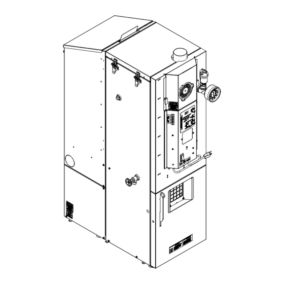
- Page 2 hF60 Parts Flue Pipe - 3” Pellet Vent Combustion Blower Cover Hopper Lid Heat Exchange Cleanout Cover Pressure Relief Valve Temperature/ Heating System Pressure Gauge Supply & Return (either side) Combustion Blower Remote Zone Control / OAT Sensor Terminal Control Board Outside Air Knockout Power Cord (either side) Circuit Breaker Side Access Boiler Drain Panel (Either Side) 1- Controlled & 1-Un-controlled Firebox Door 120VAC Outlets Firebox Draft Test Port Levelling Feet 3-90-233R24_11/13...
-
Page 3: Table Of Contents
= Contains updated information harman Central heating Appliances are built and tested to be complete home heating solutions. As with any Central heat system, a backup heating system may be required in the event of power outages or during appliance service or maintenance. -
Page 4: Options
Options Outside Air Components Inlet Cover part# 1-10-09542 Direct Vent Wall Passthrough Standard method of attaching outside air. Be Item # 1-10-677177 provides for safe passing sure to use the inlet cover to prevent birds and/ of the 3” or 4” pellet vent pipe through an or rodents from entering the intake pipe. This outside wall, while providing the attachment method requires a hole to the outside, separate for outside air. No extra holes needed. from the vent passage. water Piping Supports- bulk Storage hopper- Item # 2-00-232044B, secures to the boiler Item #1-00-73450, with 1500 lb pellet and gives the support needed for the capacity, it will automatically re-fill... -
Page 5: Installation
Installation Preparation For Installation: boiler kit materials: (refer to page 3) 1. Install 3/4” MPT boiler drain in the fitting as shown. Either side can be utilized. Note: If using the supply and return List of items shipped with the unit. on each side, either one of the returns is going to need 1 - 3/4” Boiler Drain the drain valve incorporated. 1 - 3/4” Safety Relief Valve Note: Use Teflon pipe thread sealant or Teflon tape on All threads before connections are made. 1 - 1/2” Dual Temperature/Pressure Gauge 2. Install the 1/2” MPT temperature/pressure gauge in fitting 1 - Outdoor Air Sensor where shown. - Page 6 Installation Minimum non-combustible floor protection area Placement and System design: The first thing that needs to be done is deciding where and how the boiler will be installed. Things that need to be taken into consideration are the NON-COMBUSTIBLE intended use of the boiler. For example, is the boiler going FLOOR PROTECTION to be used as a secondary or backup heating system? If it is to be used in conjunction with an existing oil or gas boiler system will it be piped in parallel or in series? The answers to these and other questions can be determined by talking 46 7/8” [1190.63mm]US to your certified dealer or a qualified HVAC or plumbing 48 7/8” [1241.43mm]CAN contractor. This will ensure that the boiler is installed and 16”...
- Page 7 Installation minimum Clearances To Combustible materials Sidewall To Appliance A 6” (152 mm) mur latéral à l’Appareil backwall To Appliance b 6” (152 mm) mur Arrière à l’Appareil Stove Top To Ceiling 16” (406 mm) haut du Poêle au Plafond Stove Front To Combustibles d 48”...
-
Page 8: Venting
venting requirements for Terminating the venting I. The clearance to service regulator vent outlet must be a minimum of 6 feet. WARNING: Venting terminals must not be recessed into a wall or siding. J. The clearance to a non-mechanical air supply inlet to the building or the combustion air inlet to any other appliance NOTE: Only PL vent pipe wall pass-throughs and fire stops must be a minimum of 48”. should be used when venting through combustible materials. K. The clearance to a mechanical air supply inlet must be a NOTE: Always take into consideration the effect the prevailing minimum of 10 feet. wind direction or other wind currents will cause with flyash and /or smoke when placing the termination. L. The clearance above a paved sidewalk or a paved driveway located on public property must be a minimum of 7 feet. In addition, the following must be observed: M. The clearance under a veranda, porch, deck or balcony A. The clearance above grade must be a minimum of 12”. must be a minimum of 12 inches. (See b. also) B. The clearance to a window or door that may be opened NOTE: The clearance to vegetation and other exterior must be a minimum of 48” to the side, 48” below the combustibles such as mulch is 36” as measured from the window/door, and 12” above the window/door. - Page 9 venting venting Use only 3” pellet vent pipe to vent your pellet boiler. A combustion blower is used to extract the combustion gases from the firebox. This creates a negative pressure in the firebox and a positive pressure in the venting system as shown in Fig. 4. The longer the vent pipe and more elbows used in the system, the greater the flow resistance, and the greater the chance for creosote accumulation. Because of these facts we recommend using as few elbows as possible The Total Lineal Feet and 18 feet or less of vent pipe. The maximum horizontal run Decreases as the Altitude Increases should never exceed 8 feet. Be sure to use wall and ceiling pass through fittings (which are approved for pellet vent pipe ) when going through combustible materials.
- Page 10 venting The minimum vent configuration is a 90° or Tee on a starter Fig. 5 collar and a 24” length horizontal through an exterior wall. A cap on the end should direct the flue gases down and away from the structure. See Fig. 5. The maximum horizontal length is 8 feet. The minimum termination height above the exterior grade is 18”. The maximum total length of any configuration is 18 feet*. 3” Type “L” or * (see venting graph on page 10 for exceptions) “PL” Vent pipe NOTE: Cleanout Tee’s should always be used on the transitions to horizontal pipe to allow easy access for cleaning.
- Page 11 venting Installation To reduce probability of reverse drafting during a INSTAllATION IS TO bE PErFOrmEd bY A power failure, hearth & home Technologies strongly QuAlIFIEd INSTAllEr. recommends: • Installing the pellet vent with a minimum vertical rise of five feet. Preferably terminating above the roof line. NOTE: All installation clearances and restrictions must be adhered to. • Installing an outside air connection to the appliance.
- Page 12 Installation NOTE: If outside air is installed, the inlet cover should not be placed in an area where drifting of snow or ice will build up, blocking the intake air supply. Hearth & Home Technologies strongly recommends the use of outside air for all pellet boiler applications. Inlet Cover part# 1-10-08542 Per national building codes, consideration must be given to combustion air supply for all appliances in the vicinity of the pellet boiler. Failure to supply adequate combustion air for all appliance demands may lead to backdrafting of...
-
Page 13: Plumbing
Installation-Plumbing NOTE: ALWAYS REFER TO THE INDIVIDUAL COMPONENTS TYPICAL BOILER HOT WATER PIPING SHOWING AIR REMOVAL SYSTEM, PROVISIONS FOR THE RECOMMENDED INSTALLATION INSTRUCTIONS FOR THE PROPER EXPANSION OF WATER AND THE AUTOMATIC COLD WATER SUPPLY. ALSO SHOWN BUT NOT MOUNTING POSITION AND LOCATION WITHIN THE PIPING SYSTEM. NECESSARILY NEEDED IS THE BOILER BYPASS LINE. - Page 14 Installation-Plumbing boilers intended to be connected to an existing boiler or boiler system shall: 1. Be capable of being installed without interfering with the normal delivery of heated water from the original boiler to the radiation system. 2. Be capable of being installed to operate as intended without affecting the operation of the electrical and mechanical safety controls of the original boiler. 3. Provide, upon completion of the installation, for a change over from one fuel to the other without requiring the manual adjustment of any controls or components other than the thermostats. 4. Be compatible with the operation of a service water-heating coil within the original boiler without bypassing the operation of the solid-fuel boiler. 5. Have provision for preventing, or adequate water capacity within the boiler to prevent, damage to the boiler from loss of circulation due to electrical power failure. 6. Be capable of being installed without changing the function of the control or rewiring of the original boiler. A wiring interconnection is permitted. The electrical system of both boilers shall be powered from a single branch circuit without exception.
- Page 15 Installation-Plumbing NOTE: ALWAYS REFER TO THE INDIVIDUAL COMPONENTS RECOMMENDED EXAMPLE OF PIPING IN SERIES WITH INSTALLATION INSTRUCTIONS FOR THE PROPER MOUNTING POSITION AND AN EXISTING OPERATIONAL BOILER LOCATION WITHIN THE PIPING SYSTEM. NOTICE: When installing with the Atmospheric Conversion, all of the pressurized system components shown are not necessary.
- Page 16 Installation-Plumbing TYPICAL BOILER HOT WATER PIPING SHOWING AIR REMOVAL SYSTEM, PROVISIONS FOR THE NOTE: ALWAYS REFER TO THE INDIVIDUAL COMPONENTS RECOMMENDED INSTALLATION INSTRUCTIONS FOR THE PROPER EXPANSION OF WATER AND THE AUTOMATIC COLD WATER SUPPLY. ALSO SHOWN IS THE AUTOMATIC MOUNTING POSITION AND LOCATION WITHIN THE PIPING SYSTEM.
- Page 17 Installation-Plumbing EXAMPLES OF TYPICAL DOMESTIC HOT WATER STORAGE PIPING EXAMPLE #2 EXAMPLE #1 CAUTION: No domestic water temperature CAUTION: No domestic water HIGHER regulation shown temperature TEMPERATURE regulation shown WATER (IF NEEDED) FROM BOILER FROM BOILER TEMPERED HOT WATER FOR COLD SHOWERS AND FAUCETS COLD...
- Page 18 Installation-Plumbing EXAMPLE OF A COMBINATION HIGH/LOW MULTI-ZONE HEATING SYSTEM NOTE: ALWAYS REFER TO THE INDIVIDUAL COMPONENTS RECOMMENDED INSTALLATION INSTRUCTIONS FOR THE PROPER MOUNTING POSITION AND WITH INDIVIDUAL ZONE CIRCULATORS LOCATION WITHIN THE PIPING SYSTEM. NOTICE: When installing with the Atmospheric Conversion, all of the (HIGH TEMPERATURE) BASEBOARD HEAT pressurized system components shown are not necessary.
-
Page 19: Electrical
Installation with A hot Air System Electrical interconnection of the HF60 to an existing heat pump, or fuel-fired hot air furnace: Interconnection with a heat pump will generally require a second thermostat to be installed. It is recommended that a new electronic thermostat be installed as close to the existing thermostat as possible. Installing within one foot of the existing thermostat is recommended for ease of interconnection and similar temperature sensing ability. If programmability is desired, both thermostats should have this capability. If only the new thermostat is programmable, you’ll need to keep the existing thermostat set several degrees below the lowest programmed temperature setting of the new thermostat. NOTE: In this configuration, if the HF60 cannot maintain the desired thermostat setting, the room will be allowed to cool to the lower set point of the existing thermostat before allowing the heat pump to operate. Special note: Even if the heat pump has a multi-stage thermostat, it cannot be re-wired to make the first stage control the HF60, and the second stage control the heat pump. All multi-stage heat pump thermostats are interconnected so that the compressor unit and/or the changeover solenoid activate with the first stage only. Controlling the existing furnace fan during overheat situation. Following the wiring diagram on the next page, you will need to supply and install a piece of 18/3 Thermostat wire between the low-voltage control terminal strip on the upper left-hand side of the HF60’s control cover, to the low-voltage control of the existing furnace. - Page 20 Installation with A hot Air System Existing T'stat New T'stat set 3° below new t'stat set 3° above existing t'stat W1 O/B SPLICE ( by installer ) Existing T'stat Wiring New T'stat Wire ( by installer ) LOW VOLTAGE SPLICE ( by installer ) Through grommet in control cover...
- Page 21 Installation with A hot Air System - fan only capable Existing T'stat New T'stat set 3° below new t'stat set 3° above existing t'stat W1 G W1 G SPLICE ( by installer ) New T'stat Wire Existing T'stat ( by installer ) Wiring LOW VOLTAGE Through grommet...
- Page 22 Connection with a 2-wire hot air system EXISTING BURNER / FAN SYSTEM ( GAS, OIL, ELECTRIC) Return Neut Return factory wiring to circulator outlet 3-90-233R24_11/13...
- Page 23 Connection with a wireless thermostat WIRELESS THERMOSTAT WIRING BROWN to control board BROWN LT.BLUE LT.BLUE to control board GREEN/YELLOW Installer Supplied Wireless T’stat Receiver ORANGE from control VIOLET from control GREEN/YELLOW WHITE GREEN R1 RELAY LOW VOLTAGE Grainger#2XC02 Omron LY2F 120V LT.BLUE BROWN BROWN...
- Page 24 Installation draft Test Procedure After the venting is completed, the firebox draft will need to be checked and possibly adjusted. After removing the plug bolt from the draft hole (3/16” hex key wrench) shown in Fig. 9, insert the draft meter tube. The hopper lid must be latched during this test. (It is recommended that the draft meter have a scale of 0 to 1” WC.) Turn the feed adjuster to “Test”. This will start the combustion blower and allow you to check and record the High Draft ______ - IWC date _______ The maximum draft allowed is -.9” Water Column (-224 Pa). There is no adjustment for the High Draft, other than re-positioning the combustion blower fan blade on its shaft, or a change in the venting configuration. After the first 60 seconds the “Test” mode lowers the combustion blower voltage to the Low Burn voltage. During this lowered voltage cycle, the low draft must be checked and adjusted if necessary. The recommended low draft setting should be between -.45 and -.55 IWC. Depending on the draft...
-
Page 25: Operation
Operation Power Light Feed adjuster Indicates power to the control Sets the maximum feed rate board. (Ready) Test Combustion blower, feed Status Light motor and safety dump Will be lit anytime the unit is zone are fully energized for in operation. the first minute. -
Page 26: Water Temperature
Operation Setting The boiler Temperature without the Outdoor Air Temp - Sensor Installed To set the maximum boiler water temperature, simply turn the Max. Temp. water temperature dial to the desired setting. The control and the boiler will then perform to achieve and maintain the set temperature. The Min. Temp. Knob is the boiler water temperature minimum, or the lowest temperature the water will go before the unit re-starts. Turning the knob fully counterclockwise is the “OFF” position, while turning the knob clockwise, past the 140 degree marking, is the “ON” position. with The Outdoor Air Temp - Sensor Installed Maximum boiler temp setting is as described above, with the added feature of automatic maximum water temp controlled by the OAT sensor. - Page 27 Operation 3-90-233R24_11/13...
- Page 28 Operation Starting A Fire Automatically 1. Turn mode Selector to “OFF”. This resets the control in addition to turning it off. 2. Clean burnpot with scraper. This is typically a weekly maintenance procedure, but, depending on the fuel being burned, may need done more frequently. Cleaning the burn pot with the scraper with a small amount of new fuel in the bottom is not a problem. First, scrape the ashes from the front of the burn pot into the ash pan. Then scrape the hole grid surface downward into the burn pot. When the stove is ignited these scrapings will be pushed out by the feeder.
- Page 29 Operation 4. If Starting After an Empty hopper, Turn Feed Adjuster to “TEST” (for one 60 second cycle). This will charge pellets into the auger tube and also allow you to check the motors for operation. NOTE: The auger motor will not operate with any of the doors or hopper lid open. 5. Turn Feed Adjuster to #5. If this is your first fire or you are trying a new fuel, set the feed adjuster to #5. This setting works well with the average wood pellets, but may need adjusted for your particular fuel. After you know a feed...
- Page 30 Operation 7. Open the firebox door to access the burnpot. 8. Turn the mIN. TEmP. dial on the control board to the desired Minimum temperature. This will start the lighting process if the temperature at the aquastat sensor is approximately 5° F. less than the set temperature on the MAX TEMP. dial. Fig. 13 9. Fill hopper with pellets and remove ashes as required. Type of Fuel - Use pelletized wood only. The lower the 8.
- Page 31 Operation 11. Apply starting gel as shown in Fig. 15 12. light The Starting gel with A match. 13. Close The doors - The fire will light and the control will adjust the rate of burn to the proper level, according to the MAX TEMP dial setting. NOTICE: when burning the boiler in the manual Fig. 15 ignition mode, there must be an overheat dump zone incorporated into the plumbing system.
-
Page 32: Maintenance
maintenance burnpot Cleaning: The burnpot should be cleaned no less than once a week. For best operation the burnpot should be cleaned every time the hopper is filled with pellets. The fire does not have to be out to scrape the burnpot although it is recommended the boiler be on minimum burn at the time of cleaning. Scrape the CAuTION: wear gloves To Prevent burns. burnpot to remove any carbon Use the flat end of the scraper provided to scrape down deposits which over the holed surface of the burnpot grate. See Fig. 17. It is may have formed. not necessary to clean out the scrapings from this cleaning because they will be pushed out as the auger operates. Scraping can be done while Note: Make a special effort to scrape the bottom inside the boiler is corners of the burnpot where the auger tube enters the in operation,... - Page 33 maintenance Inner refractory lining The firebox and heat exchanger tube access areas are lined with high-temperature, fibrous ceramic insulation panels (much like spacecraft tiles). The surface of these panels is hardened to resist normal wear from brushing with a non- metal brush. The panels are not designed to be cleaned with the scraper or other sharp objects. Caution must be taken when cleaning these panels because damage to them is not covered by the warranty. The ash pan slides into the unit on a rail system. This keeps the ash pan from contacting the sides and floor refractory panels. Caution must be taken to ensure there is nothing on the floor surface prior to inserting the ash pan. Ash removal It is recommended to remove the ashes when the boiler is not in operation. This lessens the chances of coming in contact with hot surfaces. Ashes can be removed while in operation but, extra care must be taken including wearing protective gloves. Open The Firebox door Firebox Refractory Swing the latch downward and open the door as shown in Fig. 21.
- Page 34 maintenance Firebox Baffle Removal Install the Cleanout Cover Lift Handle by using the spring latch holes. Install one end of the Cleanout Cover Lift Handle into the back spring latch hole while the other side gets placed into the one positioned on the opposite side as pictured below. After the Clean Out Cover has been removed you can now remove the spirals. Using the Spiral Removal Tool, clamp through the opening located at the top of each spiral and slowly pull upward as shown below. The tabs go into the slots on the baffle and the latch flips Pull upward slowly downward to seal at the angle. Lift the latch and lift the baffle off of the tabs for removal. Ashes from the heat exchange tubes can be cleaned from this area. Sliding the firebrick from one side to the other will allow more space for baffle removal.
- Page 35 maintenance The boiler muST be OFF at the circuit breaker, and COOl before you attempt to clean the combustion blower. Blower Cover The wire to the combustion blower doesn’t need to be disconnected during the cleaning process. Loosen the three (3) thumb screws about 4 turns each. See Fig. 23. Hold the motor head with one hand and the blower plate handle with the other hand. Pull outward on the plate handle until the complete unit comes loose. Now rotate the Latch plate counter-clockwise about 1/8 turn. This will allow the complete assembly to be removed from the blower chamber. Clean the blower fan blade and the blower plate sealing Fig.
- Page 36 Uninterruptible Power Supply (UPS) UPS battery back-ups are available online or at computer and office equipment stores. Your Harman® appliance with Rev E or later software available beginning in November 2010 may be plugged directly into a Harman® approved UPS: •...
- Page 37 Special Instructions/ Power Failure Requirements as specified by CAN/CSA- B366.1 Operation of the hF60 during a Power Failure - A supply of 120 VAC is required for operation. In the event of a power failure, the unit will not operate. The boiler can be powered alternatively using the Surefire 512 Battery Back-up system, or a generator. The generator must be properly filtered to maintain a constant sine wave of 60 cycle, with a steady 120 Volt output. EXAMPLE OF PIPING IN ACCORDANCE WITH (CAN/CSA-B366.1) A POWER FAILURE HEAT DISSIPATION LOOP TO NORMAL HEATING DEMAND (HIGH TEMPERATURE) BASEBOARD HEAT BASEBOARD MUST BE AT LEAST 24"...
-
Page 38: Troubleshooting
Troubleshooting FEEdEr dOES NOT FEEd SmOkE IS vISIblE COmINg OuT OF vENT 1. No pellets in hopper. 1. Air-fuel ratio is too rich. 2. Firebox draft may be too low for low draft pressure switch a. Feed rate too high. in feeder circuit to operate. Check for improperly closed b. Draft too low caused by a gasket leak. doors, loose or missing gasket on doors or hopper lid, or lOw hEAT OuTPuT a faulty pressure switch. 1. Feed rate too low 3. Feed motor will not run until the ESP senses 170 deg. 2. Draft too low because of gasket leak. F. Maybe you did not put enough pellets in the burn pot before lighting the fire manually. 3. Poor quality or damp pellets 4. Something is restricting flow in the hopper or causing the 4. Combination of 1 and 2. -
Page 39: Specifications
Specifications BTU Input Range= 0, and 9350 to 60,000* 0 BTU if system is satisfied. Min. Burn = 1.1 pound per hour Max. Burn = 7 pounds per hour * 8500 BTU per pound figures Electrical 120 vAC 60 hz Combustion blower 1.4 AMP Auger motor .7 AMP Igniter element 2.3 AMP Control board .05 AMP Approximate operating wattage .2 KWH Shipping Weight (Includes Packaging) 525 Lbs. duty Cycle 80% - Although this model is rated for 60,000 BTU on high burn, it is not intended to remain on high burn continuously. 3-90-233R24_11/13... -
Page 40: Wiring Diagram
wiring diagram PLUG WHITE BLACK BLUE WHITE GREEN GREEN GREEN/YELLOW BLUE BROWN YELLOW LT.BLUE BLACK BLACK BLUE GREEN/YELLOW 3-90-233R24_11/13... -
Page 41: Warranty
warranty hearth & home Technologies lImITEd lIFETImE wArrANTY Hearth & Home Technologies, on behalf of its hearth brands (”HHT”), extends the following warranty for HHT gas, wood, pellet, coal and electric hearth appliances that are purchased from an HHT authorized dealer. wArrANTY COvErAgE: HHT warrants to the original owner of the HHT appliance at the site of installation, and to any transferee taking ownership of the appliance at the site of installation within two years following the date of original purchase, that the HHT appliance will be free from defects in materials and workmanship at the time of manufacture. After installation, if covered compo- nents manufactured by HHT are found to be defective in materials or workmanship during the applicable warranty period, HHT will, at its option, repair or replace the covered components. HHT, at its own discretion, may fully discharge all of its obligations under such warranties by replacing the product itself or refunding the verified purchase price of the product itself. The maximum amount recoverable under this warranty is limited to the purchase price of the product. This warranty is subject to conditions, exclusions and limitations as described below. wArrANTY PErIOd: Warranty coverage begins on the date of original purchase. In the case of new home construction, warranty coverage begins on the date of first occupancy of the dwelling or six months after the sale of the product by an independent, authorized HHT dealer/ distributor, whichever occurs earlier. The warranty shall commence no later than 24 months following the date of product shipment from HHT, regardless of the installation or occupancy date. The warranty period for parts and labor for covered components is produced in the following table. The term “Limited Lifetime” in the table below is defined as: 20 years from the beginning date of warranty coverage for gas appliances, and 10 years from the beginning date of warranty coverage for wood, pellet, and coal appliances. These time periods reflect the minimum expected useful lives of the designated components under normal operating conditions. Warranty Period HHT Manufactured Appliances and Venting Components Covered Parts Labor Wood Pellet Coal Electric Venting Wood All parts and material except as covered by Conditions,... -
Page 42: Warranty Conditions
warranty wArrANTY CONdITIONS: • This warranty only covers HHT appliances that are purchased through an HHT authorized dealer or distributor. A list of HHT authorized dealers is available on the HHT branded websites. • This warranty is only valid while the HHT appliance remains at the site of original installation. • This warranty is only valid in the country in which the HHT authorized dealer or distributor that sold the appliance resides. • Contact your installing dealer for warranty service. If the installing dealer is unable to provide necessary parts, contact the nearest HHT authorized dealer or supplier. Additional service fees may apply if you are seeking warranty service from a dealer other than the dealer from whom you originally purchased the product. • Check with your dealer in advance for any costs to you when arranging a warranty call. Travel and shipping charges for parts are not covered by this warranty. wArrANTY ExCluSIONS: This warranty does not cover the following: • Changes in surface finishes as a result of normal use. As a heating appliance, some changes in color of interior and exterior surface finishes may occur. This is not a flaw and is not covered under warranty. • Damage to printed, plated, or enameled surfaces caused by fingerprints, accidents, misuse, scratches, melted items, or other external sources and residues left on the plated surfaces from the use of abrasive cleaners or polishes. • Repair or replacement of parts that are subject to normal wear and tear during the warranty period. These parts include: paint, wood, pellet and coal gaskets, firebricks, grates, flame guides, batteries and the discoloration of glass. • Minor expansion, contraction, or movement of certain parts causing noise. These conditions are normal and com- plaints related to this noise are not covered by this warranty. • Damages resulting from: (1) failure to install, operate, or maintain the appliance in accordance with the installation instructions, operating instructions, and listing agent identification label furnished with the appliance; (2) failure to install the appliance in accordance with local building codes; (3) shipping or improper handling; (4) improper opera- tion, abuse, misuse, continued operation with damaged, corroded or failed components, accident, or improperly/ incorrectly performed repairs; (5) environmental conditions, inadequate ventilation, negative pressure, or drafting caused by tightly sealed constructions, insufficient make-up air supply, or handling devices such as exhaust fans or forced air furnaces or other such causes; (6) use of fuels other than those specified in the operating instructions; (7) installation or use of components not supplied with the appliance or any other components not expressly authorized and approved by HHT; (8) modification of the appliance not expressly authorized and approved by HHT in writing;... -
Page 43: Testing Label
Harman HydroFlex 60 Pellet Boiler Testing label Label measures: 7.5" high X 6.5"wide hydroFlex 60 LISTED PELLET FUEL CENTRAL OR SUPPLEMENTARY FURNACES FOR RESIDENTIAL USE APPAREIL DE CHAUFFAGE CENTRAL OU SUPPLÉMENTAIRE ENREGISTRÉ DE GRANULÉS OMNI-Test Laboratories, Inc. COMBUSTIBLES POUR USAGE DANS LES RÉSIDENCES Report #/Rapport #135-O-20-6.2, #135-O-20b-6.2... -
Page 44: Service Parts
hF60 Service Parts Beginning Manufacturing Date: July 2009 hydrofl ex 60 Central heat Ending manufacturing date: Active 1-90-232000 Part number list on following page. 11/13 3-90-233R24_11/13... - Page 45 hF60 Service Parts Beginning Manufacturing Date: July 2009 Ending manufacturing date: Active IMPORTANT: THIS IS DATED INFORMATION. Parts must be ordered from a dealer or distributor. Stocked hearth and home Technologies does not sell directly to consumers. Provide model number and serial number when requesting service parts from your dealer or distributor. at depot ITEm description COmmENTS PArT NumbEr Plumbing Support Kit - Qty. 2 req. 1-10-232044 Firetube Cleanout Door Assembly 1-10-232060A Firetube Lift & Clean Kit 1-00-232120 Draft Section Refractory Side Qty 2 req 3-40-232054 1/4-20 x 1-1/2" Wingscrew with Collar Pkg of 10...
- Page 46 hF60 Service Parts Beginning Manufacturing Date: July 2009 Ending manufacturing date: Active IMPORTANT: THIS IS DATED INFORMATION. Parts must be ordered from a dealer or distributor. Stocked hearth and home Technologies does not sell directly to consumers. Provide model number and serial number when requesting service parts from your dealer or distributor. at depot ITEm description COmmENTS PArT NumbEr Tube Cleanout Cover Plate Qty 2 req 2-00-232052B Tube Cleanout Latch Qty 2 req 2-00-232009L Ceramic Insert Pkg of 10 3-20-05238-10 Flame Guide 3-00-03000...
- Page 47 hF60 Service Parts Beginning Manufacturing Date: July 2009 Ending manufacturing date: Active IMPORTANT: THIS IS DATED INFORMATION. Parts must be ordered from a dealer or distributor. Stocked hearth and home Technologies does not sell directly to consumers. Provide model number and serial number when requesting service parts from your dealer or distributor. at depot ITEm description COmmENTS PArT NumbEr Spiral Fire Tube Baffl e Pkg of 8 2-00-232053-8 ESP Probe 3-20-00844 Aqua Temp Sensor Cable 3-20-72180 1/2" Foam Insulation 3-44-232087...
- Page 48 hF60 Service Parts Beginning Manufacturing Date: July 2009 Ending manufacturing date: Active #11 Feeder Asembly 11.1 11.12 11.16 11.15 11.14 11.2 11.13 11.11 11.3 11.10 11.9 11.4 11.5 11.8 11.7 11.6 IMPORTANT: THIS IS DATED INFORMATION. Parts must be ordered from a dealer or distributor. Stocked hearth and home Technologies does not sell directly to consumers. Provide model number and serial number when requesting service parts from your dealer or distributor.
- Page 49 Service & maintenance log Date Of Service Performed By Description Of Service 3-90-233R24_11/13...
- Page 50 Service & maintenance log Date Of Service Performed By Description Of Service 3-90-233R24_11/13...
- Page 51 At Harman, we build each product to a standard, not a price. This powerful heating appliance boasts uncompromising attention to detail and helps preserve our planet by using environmentally responsible fuels. (Signature of Boxer) Your premium quality hearth product designed and assembled by the experienced and skilled members at Harman in Halifax, PA, USA.
Need help?
Do you have a question about the HydroFlex 60 Pellet Boiler and is the answer not in the manual?
Questions and answers