Harman PB 105 Installation And Operating Manual
Pellet boiler
Hide thumbs
Also See for PB 105:
- Installation & operating manual (40 pages) ,
- Installation & operating manual (48 pages) ,
- Owner's manual (52 pages)
Table of Contents
Advertisement
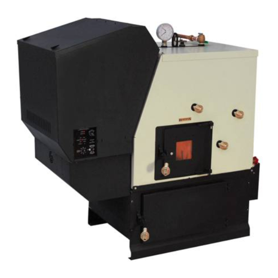
The harman pb 105 pellet boiler
WArNINg! rISk OF FIrE Or ExplOISION!
•
ImprOpEr INSTAllATION, OpErATION Or mAINTENANCE OF ThIS bOIlEr CAN CAuSE INjurY Or dEATh.
•
FOllOW All INSTruCTIONS CONTAINEd IN ThIS mANuAl
bEFOrE INSTAllATION ANd uSE OF ThIS bOIlEr:
•
plEASE rEAd ANd uNdErSTANd ThIS ENTIrE mANuAl.
CONSulT YOur lOCAl AuThOrITIES hAvINg jurISdICTION.
•
CONTACT YOur muNICIpAl buIldINg dEpArTmENT, FIrE dEpArTmENT, Or OThEr lOCAl AuThOrITIES
bEFOrE INSTAllINg ThIS bOIlEr.
•
lOCAl buIldINg rEgulATIONS mAY rEquIrE SpECIAl pErmITS, rESTrICTIONS ANd INSpECTION
rEquIrEmENTS.
Installation & Operating manual
"Ce manuel est disponible en Français sur demande"
SAFETY NOTICE
SAvE ThESE INSTruCTIONS
r14
3-90-07205
Advertisement
Table of Contents

Related Manuals for Harman PB 105


Summary of Contents for Harman PB 105
- Page 1 “Ce manuel est disponible en Français sur demande” WArNINg! rISk OF FIrE Or ExplOISION! • ImprOpEr INSTAllATION, OpErATION Or mAINTENANCE OF ThIS bOIlEr CAN CAuSE INjurY Or dEATh. • FOllOW All INSTruCTIONS CONTAINEd IN ThIS mANuAl bEFOrE INSTAllATION ANd uSE OF ThIS bOIlEr: •...
- Page 3 parts locations...
-
Page 4: Table Of Contents
Please read this entire manual before you install and use your new boiler. Failure to follow instructions may result in property damage, bodily injury, or even death. -
Page 5: Warranty
Hearth & Home Technologies Inc., on behalf of its Harman™ brand (”HHT”), extends the following warranty for all Harman™ furnace and boiler products (“Products”) that are purchased from an HHT authorized dealer. Warranty Coverage: Subject to the conditions, exclusions and limitations set forth below, HHT warrants to the original... -
Page 6: Assembly
Boiler Kit Materials: (Refer to page 3) List of items contained within the boiler kit shipped with the unit. 1 - Control board cover 1 - Access cover (Hopper Swing Plate Knob) 5 - Spring Handles 1 - 1/2” Boiler Drain 1 - 3/4”... - Page 7 Wire nut or butt splice connectors could also be used. The connections at the boiler can be done with the two 1/4” female push on connectors supplied. 8. Fasten the conduit to the ash base with the clamps provided.
- Page 8 INSTALLATION IS TO BE PERFORMED BY A QUALIFIED INSTALLER. Assembly NOTE: All installation clearances and restrictions must be adhered to. NOTE:Use only 4” diameter type “L” or “PL” venting system. Be sure to inspect and clean exhaust venting system frequently.
-
Page 9: Venting
Requirements for Terminating the Venting WARNING: Venting terminals must not be recessed into a wall or siding. NOTE: Only PL vent pipe wall pass-throughs and fire stops should be used when venting through combustible materials. NOTE: Always take into consideration the effect the prevailing wind direction or other wind currents will cause with flyash and /or smoke when placing the termination. - Page 10 Hearth & Home Technologies strongly recommends the use of outside air in all pellet boiler installations, especially those on lower level and main floor locations. Per national building codes, consideration must be given to combustion air supply to all combustion appliances.
- Page 11 The sections of pipe lock together to form an air tight seal in most cases; however, in some cases a perfect seal is not achieved. For this reason and the fact that the boiler operates with a positive vent pressure, we specify that all joints within the structure should also be sealed with silicone.
-
Page 12: Installation
See page 21 for the Draft Test procedure. This boiler may be used and installed into an existing masonry or Class A metal chimney. Certain Canadian and Local Codes may require that the chimney be fully relined. - Page 13 Inlet Cover part# 1-10-09542 Outside Air Pipe Knockout Feeder Cover Fig. 7 Outside Air Inlet Pipe Hopper/Feeder Swing Plate Knob Installation Outside Air To install outside air, use 2 3/4” I.D.galvanized steel flex pipe, part # 2-00-08544 ( 12’ 6” length) or part # 2-00-08545 ( 25’...
- Page 14 main Wiring Installation...
- Page 15 Installing Duct Installation NOTE: Cold return water temperature (Sustained temperatures below 140 degrees Fahrenheit) will lead to condensation in the firebox. This moisture can lead to creosote formation. To help minimize moisture and creosote, it is strongly recommended that some form of temperature balance is incorporated into the return water system.
- Page 16 Boilers intended to be connected to an existing boiler or boiler system shall: 1. Be capable of being installed without interfering with the normal delivery of heated water from the original boiler to the radiation system. 2. Be capable of being installed to operate as intended without affecting the operation of the electrical and mechanical safety controls of the original boiler.
- Page 17 HOSE BIB FLOW REGULATOR WILL NEED TO MATCH THE GPM RATING OF THE DOMESTIC COIL. (IF USING A DOMESTIC COIL, 4 GPM IS REQUIRED.) EXAMPLES OF TYPICAL DOMESTIC HOT WATER STORAGE PIPING EXAMPLE #1 FROM BOILER COLD DOMESTIC HOT CIRCULATOR...
- Page 18 TYPICAL BOILER HOT WATER PIPING SHOWING AIR REMOVAL SYSTEM, PROVISIONS FOR THE EXPANSION OF WATER AND THE AUTOMATIC COLD WATER SUPPLY. ALSO SHOWN IS THE AUTOMATIC MIXING VALVE. THIS COULD ALSO BE DONE BY (2) CLOSELY SPACED TEE'S. THE PROPER PIPING FOR THE INTENDED USE WILL BE DETERMINED BY THE INSTALLING CERTIFIED PLUMBER OR HVAC CONTRACTOR.
- Page 19 Installation NOTE: Cold return water temperature (Sustained temperatures below 140 degrees Fahrenheit) will lead to condensation in the firebox. This moisture can lead to creosote formation. To help minimize moisture and creosote, it is strongly recommended that some form of temperature balance is incorporated into the return water system.
- Page 20 If the water temperature continues to rise to the risk of boiling point, the feed system will stop and the boiler will shut-down. A manual reset will then be required to operate the boiler.
- Page 21 Check for obstructions. Low Draft The Control Adjustment Pot The boiler has the option to have the control panel covered or un-covered See Fig. 11. There is a pair of slots provided for each position. Simply move the cover Fig. 10 to the desired position by placing the tabs on the cover in the proper slots.
-
Page 22: Fuel Specifications
Fuel and Fuel Storage Pellet fuel quality can fluctuate from manufacturer to manufacturer, and even from bag to bag. Hearth & Home Technologies recommends using only fuel that is certified by the Pellet Fuels Institute (PFI). Fuel Material • Made from sawdust and/or other wood by-products •... -
Page 23: Operation
See explanation on page 20. Mode Selector/Min. Temp. Used to turn the boiler on or off and set the desired minimum operating temperature of the boiler. Max. Temp./ Min. Temp. Water Temperature Settings See “Setting the boiler temperature”... -
Page 24: Water Temperature
When the OAT sensor is installed, at 20° F. or below (outside temperature), the boiler will operate at the temperature set on the MAX. TEMP. knob. The boiler water temperature will decrease by 1 degree F. for every 1 degree F. in temperature rise (above 20°) of the outdoor air. - Page 25 Operation...
- Page 26 Scrape burnpot to remove any carbon build-up that may have occurred Scraping can be done while in operation Operation Starting A Fire Automatically 1. Turn Mode Selector to “OFF”. This resets the control in addition to turning it off. 2. Clean Burnpot with scraper, if necessary. This is usually a weekly maintenance procedure.
- Page 27 WATER TEMPERATURE MAX. TEMP. Operation 4. If Starting After an Empty Hopper, Turn Feed Adjuster to “TEST” (for one 60 second cycle). This will feed pellets into the auger tube and also allow you to check the motors for operation. NOTE: The auger motor will not operate with any of the doors open.
- Page 28 The automatic system will allow the fire size to be adjusted to match the heating needs and even put the fire out if necessary. If heat is needed after the fire is out, the boiler will automatically re-ignite and adjust the fire size to match the heating need.
- Page 29 The fire will light and the control will adjust the fire to the proper level according to the MAX TEMP dial setting. NOTICE: When burning the boiler in the manual ignition mode, there must be an overheat dump zone incorporated into the plumbing system.
-
Page 30: Maintenance
The fire does not have to be out to scrape the burnpot although it is recommended the boiler be on minimum burn at the time of cleaning. Note: Scraping can be done while in operation if performed through the firebox door opening. - Page 31 Remove Ash Pan Always wear gloves to remove ash pan. Grab the ash pan by the finger hold and pull it out of the boiler. Lift the ash pan by the finger hold and use it for carrying the ash pan. Close the ash door before disposing the ashes.
- Page 32 This action will remove any fly ash built up on the heat exchanger tubes. This can also be done at any time during the operation of the boiler to maintain higher efficiencies. Make sure that these rods are pushed in when cleaning is completed.
- Page 33 (See Fig. 22). Flip the latches up and pull the shield away from the boiler. It can not be fully removed, it can only be moved down over the wire until it hangs on the junction box.
-
Page 34: Troubleshooting
Whenever your boiler is not burning, take the opportunity to scrape the burn pot to remove carbon buildup. A vacuum cleaner is handy to remove the residue. be sure the boiler is cold if you use a vacuum. Carbon buildup can be scraped loose with the fire burning using the special tool provided with your stove. -
Page 35: Atmospheric Conversion
Atmospheric Conversion Atmospheric Conversion: Item # 1-00-232200, provides automatic fill, and converts the heating system plumbing from pressurized to a zero pressure system. Allows for installation into more places where codes and standards restrict pressurized systems. Note that when using the atmospheric conversion, air bleeders and check valves may actually allow air into the lines. -
Page 36: Service Parts
IMPORTANT: THIS IS DATED INFORMATION. When requesting service or replacement parts for your appliance please provide model number and serial number. All parts listed in this manual may be ordered from an authorized dealer. ITEm dESCrIpTION Hopper Assembly Gasket, Hopper Throat Hopper Lid Spring Latch Control Board Plate, Studded w/label Control Board... -
Page 37: Service Parts
#8 Ash base Assembly IMPORTANT: THIS IS DATED INFORMATION. When requesting service or replacement parts for your appliance please provide model number and serial number. All parts listed in this manual may be ordered from an authorized dealer. ITEm dESCrIpTION Ash Base Gasket Ash Chamber Insul Left Side Ash Chamber Jacket Left with Relief Hole... - Page 38 View Door Mounting Plate Gasket Finished Body Weldment Cleanout Rod Cleanout Rod Repair Kit Scraper Rod Guide 4 x 4 Steel Box 1/2” NPT Boiler Drain 3/4” NPT Boiler Drain Jacket Side Right Water Jacket Insulation Right Jacket Backside Water Jacket Insulation Back...
- Page 39 #28 Feeder Assembly 28.1 28.16 28.2 28.3 IMPORTANT: THIS IS DATED INFORMATION. When requesting service or replacement parts for your appliance please provide model number and serial number. All parts listed in this manual may be ordered from an authorized dealer. ITEm description 6RPM Gear Motor...
- Page 40 IMPORTANT: THIS IS DATED INFORMATION. When requesting service or replacement parts for your appliance please provide model number and serial number. All parts listed in this manual may be ordered from an authorized dealer. ITEm dESCrIpTION #29 boiler kit 29.1 29.2 29.3 29.1 Press Temp Guage Bottom Mount 29.2...
-
Page 41: Specifications
Specifications... -
Page 42: Wiring Diagram
Wiring diagram PLUG WHITE YELLOW BLUE WHITE BLACK BLACK JUNCTION SQUARE 4" WHITE WHITE WHITE GREEN... - Page 43 power Failure backup Supply WHITE WHITE BLUE DARK WHITE motor combustion CONDUIT 3/8"FLEX...
-
Page 44: Testing Label
Testing label Wood WARNING: Risk of fire - ATTENTION: Risque de feu - Do not operate with the flue draft Ne fonctionnez pas avec l'ébauche exceeding -.9 in Water Column / -224Pa. deconduite de cheminée excédant -.9 " colonne de l'eau / -224Pa. Hearth &... - Page 45 Service record / Notes...
- Page 46 Service record / Notes...
- Page 47 Proudly Printed On 100% Recycled Paper...
Need help?
Do you have a question about the PB 105 and is the answer not in the manual?
Questions and answers