Table of Contents
Advertisement
Quick Links
Advertisement
Chapters
Table of Contents
Troubleshooting

Related Manuals for Suzuki LT-Z90K7 2007


Summary of Contents for Suzuki LT-Z90K7 2007
- Page 1 9 9 5 0 0 - 4 0 0 2 0 - 0 1 E...
-
Page 2: General Information
FOREWORD GROUP INDEX This manual contains an introductory description on the SUZUKI LT-Z90 and procedures for its inspec- tion/service and overhaul of its main components. GENERAL INFORMATION Other information considered as generally known is not included. Read the GENERAL INFORMATION section to... -
Page 3: How To Use This Manual
HOW TO USE THIS MANUAL TO LOCATE WHAT YOU ARE LOOKING FOR: 1. The text of this manual is divided into sections. 2. The section titles are listed in the GROUP INDEX. 3. Holding the manual as shown at the right will allow you to find the first page of the section easily. - Page 4 Apply molybdenum oil solution. (mixture of engine oil and SUZUKl Measure in resistance range. MOLY PASTE in a ratio of 1 : 1) Apply SUZUKI SUPER GREASE “ A ” or equivalent grease. Measure in current range. 99000-25010 Apply SUZUKI MOLY PASTE.
-
Page 5: Table Of Contents
GENERAL INFORMATION GENERAL INFORMATION CONTENTS WARNING/CAUTION/NOTE .................1- 2 GENERAL PRECAUTIONS................1- 2 SUZUKI LT-Z90K7 (’07-MODEL) ..............1- 4 SERIAL NUMBER LOCATION..............1- 4 FUEL AND OIL RECOMMENDATION ............1- 5 FUEL (FOR USA AND CANADA)............1- 5 FUEL (FOR OTHER COUNTRIES)............1- 5 ENGINE OIL AND FINAL REDUCTION GEAR BOX OIL (FOR USA) ....................1- 5... -
Page 6: Warning/Caution/Note
GENERAL INFORMATION WARNING/CAUTION/NOTE Please read this manual and follow its instructions carefully. To emphasize special information, the symbol and the words WARNING, CAUTION and NOTE have special meanings. Pay special attention to the mes- sages highlighted by these signal words. Indicates a potential hazard that could result in death or injury. - Page 7 GENERAL INFORMATION " * If parts replacement is necessary, replace the parts with Suzuki Genuine Parts or their equiva- lent. * When removing parts that are to be reused, keep them arranged in an orderly manner so that they may be reinstalled in the proper order and orientation.
-
Page 8: Suzuki Lt-Z90K7 ('07-Model)
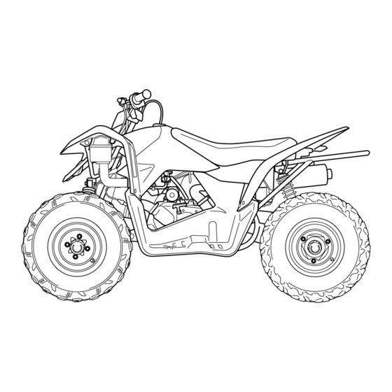
GENERAL INFORMATION SUZUKI LT-Z90K7 (’07-MODEL) RIGHT SIDE LEFT SIDE • Difference between illustration and actual vehicle may exist depending on the markets. SERIAL NUMBER LOCATION The frame serial number or V.I.N. (Vehicle Identification Number) 1 is stamped on the left side of the rear frame pipe. -
Page 9: Fuel And Oil Recommendation
Suzuki recommends the use of SUZUKI PERFORMANCE 4 MOTOR OIL or equivalent engine oil. Use of API SF/SG or SH/SJ with JASO MA. Suzuki recommends the use of SAE 10W-40 engine oil. If SAE 10W-40 engine oil is not available, select an alternative according to the following chart. -
Page 10: Break-In Procedures
GENERAL INFORMATION BREAK-IN PROCEDURES During manufacture only the best possible materials are used and all machined parts are finished to a very high standard but it is still necessary to allow the moving parts to “BREAK-IN” before subjecting the engine to maximum stresses. -
Page 11: Information Labels
GENERAL INFORMATION INFORMATION LABELS APPLIED SPECIFICATION LABEL or PLATE NAME Certification plate Compliance label Manual notice Label Tire information label (Warning no-passenger) E Tire information label (Warning no-passenger) F General warning and Age, 12 label E General warning label F No-passenger mark E No-passenger mark E F AGE, 12 label F... -
Page 12: Specifications
GENERAL INFORMATION SPECIFICATIONS DIMENSIONS AND DRY MASS Overall length................1 505 mm (59.2 in) Overall width ................875 mm (34.4 in) Overall height................915 mm (36.0 in) Wheelbase ................1 005 mm (39.6 in) Ground clearance ..............150 mm (59.0 in) Seat height................ -
Page 13: Chassis
GENERAL INFORMATION CHASSIS Front suspension..............Independent, swing axle, coil spring, oil damped Rear suspension ..............Swingarm, coil spring, oil damped Front wheel travel..............62 mm (2.4 in) Rear wheel travel ..............61 mm (2.4 in) Caster..................3.0 ° Trail ..................11 mm (0.4 in) Toe-in .................. -
Page 14: Periodic Maintenance
PERIODIC MAINTENANCE PERIODIC MAINTENANCE CONTENTS PERIODIC MAINTENANCE SCHEDULE .............2- 2 PERIODIC MAINTENANCE CHART .............2- 2 MAINTENANCE AND TUNE-UP PROCEDURES ........2- 3 AIR CLEANER ..................2- 3 EXHAUST PIPE NUTS AND MUFFLER MOUNTING BOLT ....2- 5 VALVE CLEARANCE ................2- 6 SPARK PLUG ..................2- 8 SPARK ARRESTER ................2- 9 FUEL LINE .....................2- 9 ENGINE OIL AND OIL FILTER ..............2-10... -
Page 15: Engine
PERIODIC MAINTENANCE PERIODIC MAINTENANCE SCHEDULE The chart below lists the recommended intervals for all the required periodic service work necessary to keep the vehicle operating at peak performance and economy. NOTE: More frequent servicing may be required on vehicles that are used under severe conditions. PERIODIC MAINTENANCE CHART Interval Initial... -
Page 16: Maintenance And Tune-Up Procedures
PERIODIC MAINTENANCE MAINTENANCE AND TUNE-UP PROCEDURES This section describes the servicing procedures for each item of the Periodic Maintenance requirements. AIR CLEANER Clean every 3 months. If the air cleaner is clogged with dust, intake resistance will be increased, with a resultant decrease in power output and an increase in fuel consumption. - Page 17 PERIODIC MAINTENANCE • Fill a wash pan a proper size with a non-flammable cleaning solvent. Immerse the air cleaner element in the cleaning solvent and wash it. • Press the air cleaner element between the palms of both hands to remove the excess solvent: do not twist or wring the element or it tear.
-
Page 18: Exhaust Pipe Nuts And Muffler Mounting Bolt
PERIODIC MAINTENANCE EXHAUST PIPE NUTS AND MUFFLER MOUNTING BOLT Tighten initially at 1 month and every 3 months there- after. • Remove the footrest lid. ( 5-4) • Tighten the exhaust pipe nuts 1 , muffler connection bolt 2 , and muffler mounting bolts 3 to the specified torque. -
Page 19: Valve Clearance
PERIODIC MAINTENANCE VALVE CLEARANCE Inspect initially at 1 month and every 6 months there- after. Excessive valve clearance results in valve noise and insufficient valve clearance results in valve damage and reduced power. Check the intake and exhaust valve clearances at the interval indicated above and adjust the valve clearances to specification, if necessary. - Page 20 10 N·m (1.0 kgf-m, 7.0 lb-ft) • Thoroughly wipe off oil from the fitting surfaces of the cylinder head and cover. • Apply SUZUKI BOND “1215” to the end caps of the cylinder head cover gasket as shown. 99000-31230: SUZUKI BOND “1215”...
-
Page 21: Spark Plug
PERIODIC MAINTENANCE SPARK PLUG Inspect every 6 months. Replace every 18 months. • Disconnect the spark plug cap 1 and remove the spark plug Standard Cold type CR7HSA CR8HSA DENSO U20FSR-U U22FSR-U CARBON DEPOSITS Check to see if there are carbon deposits on the spark plug. If carbon is deposited, remove it using a spark plug cleaner machine or carefully use a tool with a pointed end. -
Page 22: Spark Arrester
PERIODIC MAINTENANCE SPARK ARRESTER Clean every 6 months. • Remove the spark arrester mounting bolt 1 . • Extract the spark arrester pipe 2 from the muffler. • Clean the spark arrester pipe 2 by brush. • Reinstall the spark arrester pipe 2 . FUEL LINE Inspect every 3 months. -
Page 23: Engine Oil And Oil Filter
2-10 PERIODIC MAINTENANCE ENGINE OIL AND OIL FILTER Replace initially 1 month and every 6 months thereaf- ter. The oil should be changed while the engine is warm oil filter replacement at the above intervals, should be done together with the engine oil change. ENGINE OIL REPLACEMENT The oil should be changed while the engine is warm. - Page 24 PERIODIC MAINTENANCE 2-11 OIL FILTER REPLACEMENT • Drain the engine oil as described in the engine oil replace- ment procedure. • Remove the oil filter cap 1 and oil filter 2 . • Replace the oil filter with a new one. •...
-
Page 25: Final Reduction Gear Box Oil
2-12 PERIODIC MAINTENANCE OIL STRAINER INSPECTION AND CLEANING • Drain the engine oil as descried in the engine oil replacement procedure. • Remove the oil strainer cap 1 and oil strainer 2 . • Clean the oil strainer with compressed air also check the oil strainer for wear and damage. -
Page 26: Throttle Cable Play
PERIODIC MAINTENANCE 2-13 THROTTLE CABLE PLAY Inspect initially at 1 month and every 3 months there- after. Adjust the throttle cable play A as follows. • Loosen the lock-nut 1 of the throttle cable. • Turn the adjuster 2 in or out to obtain the correct play. Throttle cable play: 3 –... -
Page 27: Drive Belt
2-14 PERIODIC MAINTENANCE DRIVE BELT Inspect every 3 months. Replace every 6 months. REMOVAL • Remove the left footrest mudguard. ( 5-5) • Remove the left footrest bar 1 . • Remove the front cooling duct connector 2 and rear cooling duct connector 3 . - Page 28 PERIODIC MAINTENANCE 2-15 • Remove the fixed drive face 8 . • Remove the limit clutch housing nut 9 with the special tool. 09930-40113: Rotor holder • Remove the limit clutch stopper 0 and limit clutch spring A . • Remove the limit clutch pressure plate B . •...
- Page 29 2-16 PERIODIC MAINTENANCE • Remove the limit clutch friction plate E and limit clutch F . • Remove the movable driven face G and drive belt H . INSPECTION Inspect the drive belt for wear and damage. If any defects are found, replace it with a new one.
- Page 30 PERIODIC MAINTENANCE 2-17 NOTE: Degrease the movable drive face assembly. Use non-flammable cleaning solvent to wipe off oily or greasy matter and make its surfaces completely dry. • Tighten the clutch housing nut to the specified torque with the special tool. 09930-40113: Rotor holder Limit clutch nut: 75 N·m (7.5 kgf-m, 54.0 lb-ft) •...
-
Page 31: Drive Chain
* Rusted links * Kinked or binding links If any defects are found, the drive chain must be replaced. The standard drive chain is RK 530. SUZUKI recom- mends to use this standard drive chain as a replace- ment. NOTE: When replacing the drive chain, replace the drive chain and sprockets as a set. - Page 32 PERIODIC MAINTENANCE 2-19 ADJUSTING • Place the vehicle on level ground. • Loosen or tighten both chain adjusters 1 equally until the chain has 15 – 25 mm (0.6 – 1.0 in) of slack at the middle of the chain between the engine and rear sprockets as shown. Drive chain slack: Standard: 15 –...
-
Page 33: Brakes
2-20 PERIODIC MAINTENANCE • Clean the drive chain with kerosene. If the drive chain tends to rust quickly, the intervals must be shortened. • After cleaning and drying the chain, oil it with a heavy-weight engine oil. BRAKES Inspect initially at 1 month and every 3 months there- after. - Page 34 PERIODIC MAINTENANCE 2-21 FRONT AND REAR BRAKE SHOE WEAR This vehicle is equipped with brake wear limit indicators for the front and rear brake. Check brake lining wear as follows: • Make sure the brake lever play is properly adjusted. •...
-
Page 35: Tires
2-22 PERIODIC MAINTENANCE TIRES 4.0 mm Inspect every month. TIRE TREAD CONDITION Operating the vehicle with excessively worn tires will decrease riding stability and consequently invite a dangerous situation. It is highly recommended to replace a tire when the remaining depth of the tire tread reaches the following specification. -
Page 36: Steering
PERIODIC MAINTENANCE 2-23 STEERING Inspect initially at 1 month and every 3 months there- after. Steering system should be adjusted properly for smooth manip- ulation of the handlebar and safe running. TOE-IN • Place the vehicle on level ground. • Make sure the tire pressure for both tire is the same and set to the proper specification. -
Page 37: Chassis Nuts And Bolts
2-24 PERIODIC MAINTENANCE CHASSIS NUTS AND BOLTS Tighten initially at 1 month and every 3 months there- after. Check that all chassis nuts and bolts are tightened to their specified torque. (Refer to page 2-25 for the loca- tions of the following nuts and bolts.) Item N·m kgf-m... - Page 38 PERIODIC MAINTENANCE 2-25...
- Page 39 2-26 PERIODIC MAINTENANCE...
-
Page 40: General Lubrications
PERIODIC MAINTENANCE 2-27 GENERAL LUBRICATIONS Lubricate every 3 months. Proper lubrication is important for smooth operation and long life of each working part of the vehicle. Major lubrication points are indicated below. 1 Steering shaft holder 2 Brake lever holder 3 Brake cable 4 Throttle cable 5 Drive chain... -
Page 41: Compression Pressure Check
2-28 PERIODIC MAINTENANCE COMPRESSION PRESSURE CHECK The compression pressure reading of a cylinder is a good indicator of its internal condition. The decision to overhaul the cylinder is often based on the results of a compression test. Periodic mainte- nance records kept at your dealership should include compression readings for each maintenance service. Compression pressure: Standard: 1 500 kPa (15.0 kgf/cm², 213 psi) Limit: 1 300 kPa (13.0 kgf/cm², 185 psi) -
Page 42: Initial Engagement And Clutch Lock-Up Inspection
PERIODIC MAINTENANCE 2-29 INITIAL ENGAGEMENT AND CLUTCH LOCK-UP INSPECTION The LT-Z90 is equipped with a centrifugal type automatic clutch. To insure proper performance and longevity of the clutch assemblies it is essential that the clutches engage smoothly and gradually. Before checking the initial engagement and clutch lock-up two inspection checks must be performed to thoroughly check the operation of the drive train. -
Page 43: Clutch Lock-Up Inspection
2-30 PERIODIC MAINTENANCE CLUTCH LOCK-UP INSPECTION Perform this inspection to determine if the clutch is engaging fully and not slipping. • Connect a multi-circuit tester onto the spark plug high-tension code. • Start the engine. • Apply the front and rear brakes as firmly as possible. •... -
Page 44: Oil Pressure Check
PERIODIC MAINTENANCE 2-31 OIL PRESSURE CHECK Check the engine oil pressure periodically. This will give a good indication of the condition of the moving parts. Oil pressure: 10 – 40 kPa (0.1 – 0.4 kgf/cm², 1.4 – 5.7 psi) at 3 000 r/min, Oil temp. at 60 °C (140 °F) If the oil pressure is lower or higher than the specification, the following causes may be considered. - Page 45 ENGINE ENGINE CONTENTS ENGINE COMPONENTS REMOVABLE WITH ENGINE IN PLACE ...3- 2 ENGINE LEFT SIDE ................3- 2 ENGINE RIGHT SIDE ................3- 2 ENGINE CENTER ..................3- 2 ENGINE REMOVAL AND REMOUNTING ...........3- 3 ENGINE REMOVAL ................3- 3 ENGINE REMOUNTING .................3- 7 ENGINE DISASSEMBLY ................3- 9 ENGINE COMPONENTS INSPECTION AND SERVICE ......3-18 CYLINDER HEAD COVER ..............3-18...
-
Page 46: Engine Components Removable With Engine In Place
ENGINE ENGINE COMPONENTS REMOVABLE WITH ENGINE IN PLACE The parts listed below can be removed and installed without removing the engine from the frame. Refer to the page listed in each section for removal and installation instructions. ENGINE LEFT SIDE PARTS REMOVAL INSTALLATION... -
Page 47: Engine Removal And Remounting
ENGINE ENGINE REMOVAL AND REMOUNTING ENGINE REMOVAL Before taking the engine out of the frame, wash the engine using a steam cleaner. Engine removal is sequentially explained in the following steps. • Drain engine oil. ( 2-10) • Remove the fuel tank cover. ( 5-4) •... - Page 48 ENGINE • Remove the carburetor assembly 5 . ( 4-7) • Disconnect the generator coupler 6 . • Loosen the muffler clamp bolt. • Remove the exhaust pipe 7 . • Remove the gasket 8 . • Remove the muffler 9 .
- Page 49 ENGINE • Remove the starter motor lead wire 0 and ground lead wire • Remove the chain case cover B . • Loosen the rear shock absorber lower bolt C . • Loosen the rear axle housing bolt D . •...
- Page 50 ENGINE • Remove the engine mounting upper brackets H . • Remove the engine mounting bolts and nuts. • Remove the engine from the right side.
-
Page 51: Engine Remounting
ENGINE ENGINE REMOUNTING Remounting the engine in the reverse order of engine removal. Pay attention to the following points: NOTE: * The engine mounting nuts are self-locking. * Once the nut has been removed, it is no longer of any use. Be sure to use new nuts, and then tighten them to the specified torque. - Page 52 ENGINE • Install the muffler 3 and exhaust pipe 4 . • Tighten the muffler mounting bolt and exhaust pipe bolt to the specified torque. The removed gasket must be replaced with a new one to prevent exhaust gas leakage. Muffler mounting bolt: 23 N·m (2.3 kgf-m, 16.5 lb-ft) Exhaust pipe bolt: 23 N·m (2.3 kgf-m, 16.5 lb-ft) •...
-
Page 53: Engine Disassembly
ENGINE ENGINE DISASSEMBLY STARTER MOTOR • Remove the starter motor. SPARK PLUG • Remove the spark plug. 09930-10121: Spark plug wrench set CYLINDER HEAD COVER • Remove the cylinder head cover bolts, and then remove the cylinder head cover 1 . CYLINDER HEAD •... - Page 54 3-10 ENGINE • Align the engraved line 3 on the camshaft so it is parallel with the mating surface of the cylinder head. • Remove the cam chain tension adjuster plug cap 4 . • Insert the - screwdriver into the slotted end of cam chain ten- sion adjuster and turn the adjusting screw clockwise with the - screwdriver until the push rod locked.
- Page 55 ENGINE 3-11 • Remove the cylinder head nut 9 in diagonal stages, and then remove the cylinder head 0 . NOTE: If the cylinder head does not come off easily, lightly tap it using a plastic mallet. CYLINDER • Remove the cylinder head gasket 1 and dowel pins. •...
- Page 56 3-12 ENGINE • Draw out the piston pin 2 and remove the piston 3 . GENERATOR ROTOR COVER • Remove the generator rotor cover 1 . • Remove the gasket 2 and dowel pins. • Remove the starter idle gear 3 and starter idle shaft 4 . GENERATOR ROTOR •...
- Page 57 ENGINE 3-13 • Remove the generator rotor 2 using the special tool. 09930-34980: Rotor remover NOTE: Temporarily install the generator rotor nut to the crankshaft, and then remove the generator rotor using the special tool. Do not hit the generator rotor with a hammer, other- wise the rotor may be damaged.
- Page 58 3-14 ENGINE OIL FILTER • Remove the oil filter cap 1 . • Remove the oil filter 2 and O-ring 3 . OIL STRAINER • Remove the oil strainer cap 1 . • Remove the oil strainer 2 . RECOIL STARTER •...
- Page 59 ENGINE 3-15 MOVABLE DRIVE FACE • Remove the crankcase cover 1 . • Remove the gasket 2 and dowel pins. • Remove the fixed drive face nut 3 with the special tool. 09930-40113: Rotor holder • Remove the fixed drive face fan 4 . •...
- Page 60 3-16 ENGINE • Remove the limit clutch stopper 2 and limit clutch spring 3 . • Remove the limit clutch pressure plate 4 . • Remove the limit clutch friction plate 5 and clutch housing 6 . • Remove the limit clutch friction plate 7 and limit clutch 8 . •...
- Page 61 ENGINE 3-17 • Remove the movable drive spacer A and movable drive face assembly B . NOTE: Movable drive face disassembly. ( 3-51) CRANKCASE • Remove the left crankcase bolts. • Separate the crankcase with the special tool. 09920-13120: Crankcase separating tool NOTE: Fit the crankcase separating tool to the right crankcase, so that the tool plate is paralleled with the end face of the crankcase.
-
Page 62: Engine Components Inspection And Service
3-18 ENGINE ENGINE COMPONENTS INSPECTION AND SERVICE CYLINDER HEAD COVER DISASSEMBLY • Remove the breather plate 1 . • Remove the gasket 2 . INSPECTION Inspect the cylinder head cover for carbon deposit. If the clogged are found, clean the cylinder head cover. REASSEMBLY •... -
Page 63: Cylinder Head
ENGINE 3-19 • Install the breather plate 2 . • Apply a small quantity of THREAD LOCK SUPER “1322” to the breather plate bolts and tighten then securely. 99000-32080: THREAD LOCK SUPER “1322” CYLINDER HEAD DISASSEMBLY Identify the position of each removed part. Organize the parts in their respective groups (i.e., exhaust or intake) so that they can be installed in their original locations. - Page 64 3-20 ENGINE • Remove the rocker arms 6 and wave washer 7 . • Remove the cam shaft 8 . • Using the special tools, compress the valve spring and remove the two cotter halves 9 from the valve stem. 09916-14510: Valve lifter 09916-14521: Valve lifter attachment 09916-84511: Tweezers...
- Page 65 ENGINE 3-21 • Remove the oil seal D . • Remove the other valves in the same manner as described previously. CYLINDER HEAD DISTORTION Decarbonize the combustion chambers. Check the gasket sur- face of the cylinder head for distortion with a straightedge and thickness gauge, taking a clearance reading at several places indicated.
- Page 66 3-22 ENGINE VALVE HEAD RADIAL RUNOUT Place the dial gauge at a right angle to the valve head face and measure the valve head radial runout. If it measures more than the service limit, replace the valve. Valve head radial runout: Service Limit: 0.03 mm (0.001 in) 09900-20607: Dial gauge (1/100 mm) 09900-20701: Magnetic stand...
- Page 67 ENGINE 3-23 VALVE STEM WEAR If the valve stem is worn down to the limit, as measured with a micrometer, replace the valve. If the stem is within the limit, then replace the guide. After replacing valve or guide, be sure to recheck the deflection. Valve stem O.D.: Standard (IN) : 4.975 –...
- Page 68 3-24 ENGINE • Cool down the new valve guides in a freezer for about one hour and heat the cylinder head to 100 – 150 °C (212 – 302 °F) with a hot plate. Do not use a burner to heat the valve guide hole to prevent cylinder head distortion.
- Page 69 ENGINE 3-25 • If the seat width W measured exceeds the standard value or seat width is not uniform, refuse the seat using the seat cutter. Valve seat width W: Standard: 0.9 – 1.1 mm (0.09 – 0.11 in) If the valve seat is out of specification, correct the seat by servic- ing it as follows: VALVE SEAT SERVICING •...
- Page 70 3-26 ENGINE VALVE SPRING The force of the coil spring keeps the valve seat tight. Weak- ened spring results in reduced engine power output, and often accounts for the chattering noise coming from the valve mecha- nism. Check the valve spring for proper strength by measuring its free length and also by the force required to compress it.
- Page 71 ENGINE 3-27 • Put on the valve spring retainer 2 , and using the valve lifter, press down the spring, fit the valve cotter halves to the stem end, and release the lifter to allow the valve cotter 3 to wedge in between retainer and stem.
-
Page 72: Camshaft
3-28 ENGINE CAMSHAFT CAM SPROCKET INSPECTION Inspect the sprocket teeth for wear. If any worn and defects are found, replace the cam sprocket, crankshaft and cam chain as a set. CAMSHAFT BEARING INSPECTION Inspect the bearings for play, discoloration, wear and seizure. Move the outer race by finger and inspect for smooth move- ment. - Page 73 ENGINE 3-29 ROCKER SHAFT INSPECTION Inspect the rocker arm shaft for abnormal wear or damage. If any defects are found, replace it with a new one. Measure the diameter of rocker arm shaft with a micrometer. Rocker arm shaft O.D. Standard: 9.990 –...
- Page 74 3-30 ENGINE • Install the camshaft retainer screw to the specified torque. Camshaft retainer screw: 5.5 N·m (0.55 kgf-m, 4.0 lb-ft) • Install the cam chain guide mounting bolt to the specified torque. Cam chain guide mounting bolt: 10 N·m (1.0 kgf-m, 7.0 lb-ft)
-
Page 75: Cam Chain Tension Adjuster And Tensioner/Guide
ENGINE 3-31 CAM CHAIN TENSION ADJUSTER AND TENSIONER/GUIDE INSPECTION Check that the push rod slides smoothly when unlocking the spring mechanism. If push rod does not slide smoothly, replace the cam chain ten- sion adjuster with a new one. Check the contacting surface of the cam chain tensioner and guide. -
Page 76: Piston And Piston Ring
3-32 ENGINE CYLINDER BORE Inspect the cylinder wall for any scratches, nicks or other dam- age. Measure the cylinder bore diameter at six places. If any one of the measurements exceed the limit, replace the cyl- inder. Cylinder bore Standard: 45.500 – 45.515 mm (1.7913 – 1.7919 in) 09900-20530: Cylinder gauge set 09900-20513: Rod (40 mm) PISTON AND PISTON RING... - Page 77 ENGINE 3-33 PISTON PIN AND PIN BORE Measure the piston pin bore diameter using the small bore gauge. If the measurement is out of specifications replace the piston. Piston pin bore I.D.: Service Limit: 14.030 mm (0.5523 in) 09900-20605: Dial caliper gauge (10 – 34 mm) Measure the piston pin outside diameter at three positions using the micrometer.
-
Page 78: Conrod
3-34 ENGINE Piston ring thickness Standard: 1st: 0.97 – 0.99 mm (0.0382 – 0.0390 in) 2nd: 0.97 – 0.99 mm (0.0382 – 0.0390 in) PISTON RING END GAP Fit the piston ring squarely into the cylinder and measure the piston ring end gap using the thickness gauge. If any of the measurements exceeds the service limit, replace the piston ring with a new one. -
Page 79: Crankshaft
ENGINE 3-35 Push the big end of the conrod to one side and measure the side clearance using a thickness gauge. If the clearance exceeds the service limit, replace the crankshaft assembly with a new one or bring the deflection and the side clearance within the service limit by replacing the worn parts (conrod, big end bearing, crank pin, etc.) with new ones. - Page 80 3-36 ENGINE INSPECTION • Install the starter clutch in the proper direction as shown. NOTE: When installing the starter clutch onto the rotor, make sure that the arrow mark A in the bearing faces to the rotor. • Apply engine oil to the starter clutch. •...
-
Page 81: Generator
ENGINE 3-37 STARTER DRIVEN GEAR BEARING INSTALLATION • Install the bearing with the special tool. 09913-70210: Bearing installer set ( 30) The removed bearing must be replaced with a new one. NOTE: The stamped mark on the bearing must face crankcase side. GENERATOR INSPECTION ( 6-9) -
Page 82: Oil Pump
3-38 ENGINE OIL PUMP DISASSEMBLY • Remove the circrip 1 . • Remove the oil pump sprocket 2 . • Remove the oil pump case cover 3 . INSPECTION Inspect the outer rotor 1 and inner rotor 2 for any scratches or other damage. - Page 83 • Install the left crankcase oil seal with the special tool. The removed oil seals must be replaced with new ones. 09913-70210: Bearing installer set • Apply SUZUKI SUPER GREASE “A” to the lip of the oil seals. 99000-25010: SUZUKI SUPER GREASE “A” (or equivalent grease) BEARING INSPECTION •...
- Page 84 3-40 ENGINE DIASSEMBLY • Remove the bearings with the special tool. 09921-20240: Bearing remover set Bearing: REASSEMBLY • Press the bearings with the special tool. 09913-70210: Bearing installer set Bearing: The removed bearings must be replaced with new ones. NOTE: The stamped mark side of the bearing faces inside.
-
Page 85: Engine Mounting Bush
ENGINE 3-41 ENGINE MOUNTING BUSH DISASSEMBLY • Using an appropriate size steel tubes 1 and vise, remove the engine mounting bush 2 . (LH, RH and rear) INSTALLATION Using an appropriate side steel tube and vise, press in the bush into the crankcase. -
Page 86: Final Reduction Gear Box
3-42 ENGINE FINAL REDUCTION GEAR BOX DISASSEMBLY • Remove the drain plug 1 and gasket. • Drain final reduction gear box oil. • Remove the final reduction gear box cover bolts and gasket. • Remove the final reduction gear box cover 2 . •... - Page 87 ENGINE 3-43 • Remove the snap ring 8 . • Remove the chain guide 9 . • Remove the dust seal 0 and bearing retainer A . • Remove the counter shaft B with a plastic mallet. COUNTER SHAFT INSPECTION Inspect the counter shaft wear or damage.
- Page 88 3-44 ENGINE DRIVE SHAFT INSPECTION Inspect the drive shaft for wear or damage. If any defects are found, replace it with a new one. FINAL DRIVEN GEAR AND IDLE GEAR INSPECTION Inspect the final driven gear 1 and idle gear 2 for wear or dam- age.
- Page 89 ENGINE 3-45 • Remove the snap ring 4 . • Remove the rear axle shaft washer 5 . • Remove the bearing 6 with the special tool. 9913-20240: Bearing remover set ( 20) • Remove the rear axle shaft housing 7 . •...
- Page 90 9: 12 0: 17 A: 20 INSTALLATION • Apply SUZUKI BOND “1215” to the rear axle housing. 99000-31110: SUZUKI BOND “1215” (or equivalent bond) • Tighten the rear axle housing bolts to the specified torque. Rear axle housing bolt: 60 N·m (6.0 kgf-m, 43.5 lb-ft) •...
- Page 91 ENGINE 3-47 09913-70210: Bearing installer set 4, 5: 25 6: 20 The removed bearings must be replaced with new ones. • Install the rear axle housing washer 7 . • Install the snap ring 8 . • Install the oil seals with the special tool. 09913-70210: Bearing installer set ( 47) The removed oil seal must be replaced with a new one.
- Page 92 3-48 ENGINE • Install the drive shaft 9 . • Install the counter shaft 0 . • Install the idle gear A . • Apply final reduction gear box oil to the gears. • Install the final driven gear B to the counter shaft. •...
- Page 93 ENGINE 3-49 • Tighten the final reduction gear box cover bolts and drain plug E to the specified torque. Final reduction gear box cover bolts: 10 N·m (1.0 kgf-m, 7.0 lb-ft) Final reduction gear box drain plug bolt: 10 N·m (1.0 kgf-m, 7.0 lb-ft) The removed drain plug bolt gasket and final reduc- tion gear box bolt gaskets must be replace with a new one.
-
Page 94: Movable And Fixed Drive And Driven Face
3-50 ENGINE MOVABLE AND FIXED DRIVE AND DRIVEN FACE 1 Concaved washer G Limit clutch 2 Fixed drive face fan H Clutch shoe 3 Fixed drive face I Movable driven face spring 4 Drive belt J Movable driven face spring seat 5 Power reduction spacer K O-ring 6 Movable drive face... - Page 95 ENGINE 3-51 MOVABLE DRIVE FACE DISASSEMBLY • Remove the movable drive face plate 1 and dampers 2 . • Remove the rollers 3 . SPACER INSPECTION Inspect the movable drive spacer 1 and power reduction spacer 2 for wear or damage. If they are worn or damaged, replace them with new ones.
- Page 96 3-52 ENGINE DAMPER INSPECTION Inspect the dampers for wear or damage. If any defects are found, replace the dampers with new ones. MOVABLE DRIVE FACE INSTALLATION • Mount the dampers 1 on the movable drive face plate 2 . • Position the rollers 3 on the movable drive face 4 . •...
- Page 97 ENGINE 3-53 • Loosen the special tool handle slowly and remove the clutch shoe assembly 5 and spring 6 . Do not attempt to disassemble the clutch shoe assem- bly. • Remove the movable driven face spring seat 7 . •...
- Page 98 3-54 ENGINE CLUTCH SHOE INSPECTION Inspect the boss and centrifugal weight fulcrum sections for looseness, damage and operation. Inspect the clutch shoe for damage and fouling with oil on the surface. If any abnormality is found, replace the clutch shoe assembly with a new one.
- Page 99 If any damages are found, replace the then with new ones. CLUTCH SHOE/MOVABLE DRIVEN FACE DIASSEMBLY INSTALLATION • Install the new O-rings 1 . • Apply SUZUKI SUPER GREASE “A” to the oil seal lips and movable driven face inside grease groove. 99000-25030: SUZUKI SUPER GREASE “A” (or equivalent) The removed O-rings must be replaced with a new one.
- Page 100 3-56 ENGINE • Apply SUZUKI SUPER GREASE “A” to the O-rings and pin grooves. 99000-25030: SUZUKI SUPER GREASE “A” (or equivalent) • Install the rollers and pins 2 . To prevent damaging the oil seal lip from during installation, slide the lip using a 0.1-mm steel sheet as a guide.
- Page 101 ENGINE 3-57 Align the flats A of the fixed driven face end and clutch shoe plate. • Tighten the clutch shoe nut temporarily. • Remove the special tool from the clutch shoe assembly. • Tighten the clutch shoe nut to the specified torque with the special tool.
-
Page 102: Recoil Starter
3-58 ENGINE RECOIL STARTER 1 Friction plate 6 Reel 2 Spring 7 Spiral spring 3 Friction plate 8 Knob 4 Friction spring 9 Rope 5 Starter cap 0 Starter case... - Page 103 ENGINE 3-59 DISASSEMBLY • Remove the nut 1 and friction plate 2 . • Remove the spring 3 and washer 4 . • Remove the cap 5 from the knob 6 . • Untie a knot at the rope. • Remove the starter cup 7 . •...
- Page 104 Wear hand and eye protection when installing the reel, since the spiral spring may quickly unwind and cause an injury. • Apply SUZUKI SUPER GREASE “A” to the spiral spring. 99000-25010: SUZUKI SUPER GREASE “A” (or equivalent) • Turn the rope on the reel properly.
- Page 105 ENGINE 3-61 • Apply THREAD LOCK “1303” to the bolt 7 . • Tighten the bolt 7 to the specified torque. 99000-32050: THREAD LOCK “1303” (or equivalent) Recoil starter friction plate bolt: 5.0 N·m (0.5 kgf-m, 3.5 lb-ft) • Pull the rope and check that the ratchet is pushed out.
-
Page 106: Engine Reassembly
3-62 ENGINE ENGINE REASSEMBLY Reassemble the engine in the reverse order of disassembly. The following steps require special attention or precautionary measures should be taken. NOTE: Apply engine oil to each running and sliding part before reassembling. CRANKSHAFT 1 Bearing 4 Conrod 7 Crankshaft (L) 2 Sim... - Page 107 ENGINE 3-63 Never fit the crankshaft into the crankcase by striking it with a plastic hammer. Always use the special tool, otherwise the accuracy of the crankshaft alignment will be affected. CRANKCASE • Thoroughly remove the sealant material and oil stains on the mating surface of the right and left crankcases.
- Page 108 3-64 ENGINE CRANKSHAFT SHIM SELECTION • Degrease the right crankshaft web, shim and inner race of the right crankshaft bearing. • Place the removed shim 1 on the right crankshaft. • Put the plasti-gauge (special tool) cut out about 10 mm on the shim as shown.
- Page 109 ENGINE 3-65 • Apply SUZUKI BOND “1215” to the mating surface of the right crankcase as shown. 99000-31080: SUZUKI BOND “1215” (or equivalent bond) NOTE: Use of SUZUKI BOND "1215" is as follows: * Make surfaces free from moisture, oil, dust and other foreign materials.
- Page 110 3-66 ENGINE • Tighten the crankcase bolts to the specified torque. Crankcase bolt: 10 N·m (1.0 kgf-m, 7.0 lb-ft) • After the crankcase bolts have been tightened, check if the crankshaft, rotate smoothly. CAM CHAIN • Install the cam chain 1 onto the sprocket. OIL PUMP •...
- Page 111 ENGINE 3-67 • Install the oil pump cover 4 . STARTER CLUTCH AND GENERATOR ROTOR • Apply engine oil to the starter driven gear bearing and crank- shaft. • Install the starter driven gear 1 . • Degrease the tapered portion of generator rotor and also the crankshaft.
- Page 112 3-68 ENGINE GENERATOR ROTOR COVER • Before installing the starter idle gear, apply molybdenum oil solution to the hole of starter idle gear shaft. MOLYBDENUM OIL SOLUTION • Install the starter idle gear 1 , shaft 2 , dowel pins and gasket The removed gasket must be replaced with a new one to prevent oil leakage.
- Page 113 ENGINE 3-69 • Install the clutch shoe/movable driven face assembly 5 with the drive belt 6 . • Install the limit clutch friction plate 7 and limit clutch 8 . • Install the limit clutch friction plate 9 and clutch housing 0 . •...
- Page 114 3-70 ENGINE • Install the limit clutch nut D with the special tool. 09930-40113: Rotor holder Limit clutch nut: 75 N·m (7.5 kgf-m, 54.0 lb-ft) MOVABLE DRIVE • Install the fixed drive face 1 . • Install the fixed drive face fan 2 . •...
- Page 115 ENGINE 3-71 RECOIL STARTER • Install the recoil starter 1 . OIL FILTER • Apply engine oil to the O-ring 1 . • Install the O-ring 1 and oil filter 2 . The removed O-ring must be replaced with a new one to prevent oil leakage.
- Page 116 3-72 ENGINE PISTON RING • Install the piston rings in the order of oil ring, 2nd ring and 1st ring. • The first member to go into the oil ring groove is a spacer 1 . • After placing the spacer, fit the two side rails 2 . NOTE: Side designations, top and bottom, are not applied to the spacer and side rails: you can position each either way.
- Page 117 • Thoroughly wipe off oil from the fitting surface of the crank- case. • Apply SUZUKI BOND “1215” to the crankcase B as shown. 99000-31080: SUZUKI BOND “1215” (or equivalent bond) • Install the dowel pins and gasket 1 onto the crankcase.
- Page 118 3-74 ENGINE • Install the cam chain guide 2 . NOTE: Make sure that the guide 2 is inserted properly or binding of the cam chain and guide may result. • Install the dowel pins and gasket 3 . The removed gasket must be replaced with a new one to prevent oil leakage.
- Page 119 ENGINE 3-75 CAM CHAIN TENSION ADJUSTER • Apply engine oil to the push rod. • Turn the adjusting screw clockwise with a - screwdriver until the rod locked. • Install the cam sprocket 3 . • Apply a small quantity of THREAD LOCK SUPER “1322” to the cam sprocket bolt 4 .
- Page 120 CYLINDER HEAD COVER • Thoroughly wipe off oil from the fitting surfaces of the cylinder head and cover. • Apply SUZUKI BOND “1215” to the end caps of the cylinder head cover gasket as shown. 99000-31230: SUZUKI BOND “1215” (or equivalent bond) The removed gasket must be replaced with a new one to prevent oil leakage.
- Page 121 • Install the spark plug. ( 2-8) STARTER MOTOR • Apply SUZUKI SUPER GREASE “A” to the O-ring. • Install the starter motor 1 . 99000-25010: SUZUKI SUPER GREASE “A” (or equivalent grease) The removed O-ring must be replaced with new ones to prevent oil leakage.
- Page 122 FUEL SYSTEM FUEL SYSTEM CONTENTS FUEL TANK AND FUEL VALVE ..............4- 2 REMOVAL ....................4- 3 FUEL FILTER INSPECTION AND CLEANING ........4- 3 INSTALLATION..................4- 4 CARBURETOR....................4- 5 SPECIFICATIONS...................4- 6 I.D. NO. LOCATION ................4- 6 REMOVAL ....................4- 7 DISASSEMBLY ..................4- 8 CLEANING ....................4-11 INSPECTION AND ADJUSTMENT............4-11 REASSEMBLY AND INSTALLATION............4-12 Gasoline must be handled carefully in an area well ventilated and away...
-
Page 123: Fuel Tank And Fuel Valve
FUEL SYSTEM FUEL TANK AND FUEL VALVE 1 Fuel tank breather hose 5 Fuel valve 2 Fuel tank cap 6 Fuel hose 3 Fuel tank A Fuel valve bolt ITEM N·m kgf-m lb-ft 4 O-ring 0.46... -
Page 124: Removal
FUEL SYSTEM REMOVAL * Gasoline is highly flammable and explosive. * Keep heat, spark and flame away. • Remove the fuel tank cover. ( 5-4) • Turn the fuel valve to “ON” position. • Disconnect the fuel hose 1 . •... -
Page 125: Installation
FUEL SYSTEM INSTALLATION Install the fuel tank and fuel valve in the reverse order of removal. Pay attention to the following points: • Tighten the fuel valve bolts to the specified torque. Fuel valve bolt: 4.5 N·m (0.45 kgf-m, 3.0 lb-ft) The removed gaskets and O-ring must be replaced with new ones to prevent fuel leakage. -
Page 126: Carburetor
FUEL SYSTEM CARBURETOR 1 Choke lever 9 Starter plunger G Needle jet 2 Carburetor top cap 0 Washer H Main jet 3 Gasket A O-ring I Float pin 4 Spring B Spring J Float 5 Spring seat C Throttle stop screw K Gasket 6 O-ring D O-ring... -
Page 127: Specifications
FUEL SYSTEM SPECIFICATIONS ITEM SPECIFICATION Carburetor type MIKUNI VM16SH Bore size I.D.N. 08H0 Idle r/min 1 900 ± 100 r/min Float height 16 mm Main jet (M.J) Jet needle (J.N) 4LA43-1 Needle jet (N.J) E-1M Pilot jet (P.J) #17.5 Air screw (A.S) PRE-SET (1, 3 –... -
Page 128: Removal
FUEL SYSTEM REMOVAL • Remove the fuel tank cover. ( 5-4) • Remove the front cooling duct. ( 3-3) • Remove the fuel hose 1 . • Remove the air vent hose 2 . • Remove the vacuum hose 3 . •... -
Page 129: Disassembly
FUEL SYSTEM DISASSEMBLY • Remove the spring 1 and piston valve 2 from the throttle cable. • Remove the spring seat 3 . • Remove the jet needle 4 , washer 5 and spring 6 from the piston valve 2 . •... - Page 130 FUEL SYSTEM • Remove the float pin 0 . • Remove the float A . • Remove the needle valve B . • Remove the main jet C and needle jet D . • Remove the pilot jet E . •...
- Page 131 4-10 FUEL SYSTEM • Remove the choke lever J . • Remove the starter plunger K .
-
Page 132: Cleaning
FUEL SYSTEM 4-11 CLEANING Some carburetor cleaning chemicals, especially dip-type soaking solutions, are very corrosive and must be handled carefully. Always follow the chemical manufacturer’s instructions on proper use, handling and storage. • Clean all jets with a spray-type carburetor cleaner and dry them with compressed air. -
Page 133: Reassembly And Installation
4-12 FUEL SYSTEM If the needle valve is worn, as shown in the illustration, replace the needle valve assembly with a new one. Clean the fuel pas- sage of the mixing chamber with compressed air. FLOAT HEIGHT ADJUSTMENT To check the float height, turn the carburetor upside down. Mea- sure the float height A while the float arm is just contacting the needle valve with vernier calipers. - Page 134 PISTON VALVE AND SPRING • Install the piston valve 1 and spring 2 to the throttle cable. • Apply SUZUKI SUPER GREASE “A” to the O-ring 1. " 99000-25010: SUZUKI SUPER GREASE “A” (or equivalent) The removed O-ring must be replaced with a new one.
- Page 135 4-14 FUEL SYSTEM • Install the carburetor top cap 4 . • Install the intake pipe clamp 5 . • Tighten the carburetor mounting bolts 6 to the specified torque. Carburetor mounting bolt: 6 N·m (0.6 kgf-m, 4.5 lb-ft) • Install the fuel hose 7 . •...
- Page 136 CHASSIS CHASSIS CONTENTS EXTERIOR PARTS ..................5- 2 CONSTRUCTION .................. 5- 2 FASTENER REMOVAL AND INSTALLATION ........5- 3 REMOVAL ..................... 5- 4 INSTALLATION ..................5- 7 FRONT AND REAR WHEELS ..............5- 8 CONSTRUCTION .................. 5- 8 REMOVAL ..................... 5- 8 INSTALLATION ..................
-
Page 137: Exterior Parts
CHASSIS EXTERIOR PARTS CONSTRUCTION 1 Seat 7 Footrest lid 2 Front fender 8 Right footrest mudguard 3 Rear fender 9 Left footrest mudguard 4 Rear lower fender 0 Front grip 5 Right fuel tank cover A Right footrest bar ITEM N·m kgf-m lb-ft... -
Page 138: Fastener Removal And Installation
CHASSIS FASTENER REMOVAL AND INSTALLATION FASTENER Removal • Depress the head of fastener center piece 1 . • Pull out the fastener a . Installation • Let the center piece stick out toward the head so that the pawls 2 close. •... -
Page 139: Removal
CHASSIS REMOVAL SEAT • Remove the seat. FOOTREST LID • Remove the footrest lid. FUEL TANK COVER • Remove the seat. ( above) • Remove the footrest lid. ( above) • Remove the screw 1 and fastener. - Page 140 CHASSIS LEFT FOOTREST MUDGUARD • Remove the fuel tank cover. ( 5-4) • Remove the screws 1 and fasteners. • Remove the bolts 2 . • Remove the left footrest mudguard 3 . RIGHT FOOTREST MUDGUARD • Remove the fuel tank cover. ( 5-4) •...
- Page 141 CHASSIS • Remove the front fender 2 . REAR FENDER • Remove the seat. ( 5-4) • Remove the footrest lid. ( 5-4) • Remove the fuel tank cover. ( 5-4) • Remove the footrest mudguard, left and right ( 5-5) •...
-
Page 142: Installation
CHASSIS • Remove the rear lower fender fastener 6 . • Remove the rear fender 7 . FRONT GRIP • Remove the front grip. INSTALLATION Install the exterior parts in the reverse order of removal. Pay attention to the following points: FOOTREST BAR •... -
Page 143: Front And Rear Wheels
CHASSIS FRONT AND REAR WHEELS CONSTRUCTION 1 Front tire 4 Rear wheel 2 Front wheel A Wheel set nut (front & rear) ITEM N·m kgf-m lb-ft 3 Rear tire 40.0 REMOVAL • Place the vehicle on level ground. • Support the vehicle with a jack or block and remove the front and rear wheel set nuts. -
Page 144: Installation
CHASSIS INSTALLATION Install the wheels in the reverse order of removal. Pay attention to the following points: • Installing each wheel, make sure the arrow A on the tire points in the direction of rotation. • Tighten the wheel set nuts to the specified torque. Front and rear wheel set nut: 55 N·m (5.5 kgf-m, 40.0 lb-ft) -
Page 145: Tires
5-10 CHASSIS TIRES TIRE REPLACEMENT • Remove the front and rear wheels. ( 5-8) • After removing the air valve caps, release the tire pressure by depressing the valves. • Dismount the bead from the rim completely as shown. • Separate the tire from the rim using a set of tire levers and rim protectors. - Page 146 CHASSIS 5-11 NOTE: * For inspecting the tires, refer to page 2-22. * Inspect the valve cores, before installation. * When installing each tire, make sure that the arrow A on the side wall of the tire points in the direction of rotation. Also, make sure the outer side of the wheel rim is facing outward.
-
Page 147: Front Brake
5-12 CHASSIS FRONT BRAKE CONSTRUCTION 1 Wheel center cap A O-ring 2 Axle spacer B Front brake dust seal 3 Outer dust seal C Brake plate 4 Wheel hub outer bearing D Limit indicator 5 Front wheel hub E Brake cam lever 6 Spacer F Front brake cam lever bolt 7 Wheel hub inner bearing... -
Page 148: Removal
CHASSIS 5-13 REMOVAL • Remove the front wheel. ( 5-8) • Remove the wheel center cap. • Remove the cotter pin and front hub nut 1 . • Remove the front washer 2 and wheel hub 3 . • Remove the front brake shoe assembly 4 . •... -
Page 149: Inspection And Disassembly
5-14 CHASSIS INSPECTION AND DISASSEMBLY BRAKE DRUM/WHEEL HUB Inspect the brake drum and measure the brake drum I.D. to determine the extent of wear. Replace the brake drum if the measurement exceeds the service limit. 09900-20101: Vernier calipers Brake drum I.D.: Service Limit: 110.7 mm (4.35 in) BRAKE SHOE Inspect the brake shoes for wear or damage. - Page 150 CHASSIS 5-15 • Remove the dust seals with the special tool. 09913-50121: Oil seal remover WHEEL HUB BEARING Inspect the inner race play of the wheel hub bearing by hand while it is in the wheel hub. Rotate the inner race by hand to inspect for abnormal noise and smooth rotation.
-
Page 151: Reassembly And Installation
• Remove the wheel hub inner bearing with the special tool. 09941-50111: Bearing remover REASSEMBLY AND INSTALLATION BEARING • Apply SUZUKI SUPER GREASE “A” to the wheel hub bear- ings. 99000-25010: SUZUKI SUPER GREASE “A” or equivalent • Install the wheel hub inner bearing with the special tool. - Page 152 CHASSIS 5-17 • Install the dust seals with the special tool. 09913-70210: Bearing installer set The removed dust seals must be replaced with new ones. • Install the front brake drum dust seal 1 to the groove of the front brake drum 2 . •...
- Page 153 5-18 CHASSIS • Install the O-rings. • Apply SUZUKI SUPER GREASE “A” to the O-rings and cam- shaft. 99000-25010: SUZUKI SUPER GREASE “A” (or equivalent) The removed O-rings must be replaced with new ones. • Align the punched mark A of the brake cam lever with the slit B of the front brake camshaft.
- Page 154 CHASSIS 5-19 • Tighten the front hub nut to the specified torque. Front hub nut: 65 N·m (6.5 kgf·m, 47.0 Ib-ft) • Install the cotter pin. The removed cotter pin must be replaced with a new one. • Install the front wheel. ( 5-8) •...
-
Page 155: Steering And Front Suspension
5-20 CHASSIS STEERING AND FRONT SUSPENSION CONSTRUCTION 1 Front shock absorber 9 Tie-lod 2 Front suspension arm A Front shock absorber upper nut ITEM N·m kgf-m lb-ft 3 Bush B Front shock absorber lower nut 36.0 4 Steering knuckle arm C Front suspension arm bolt 36.0 5 Knuckle arm bush... -
Page 156: Handlebar Upper Holder
CHASSIS 5-21 1 Handlebar upper holder 7 Steering shaft lower dust seal 2 Handlebars 8 Steering shaft bush 3 Handlebar lower holder 9 O-ring ITEM N·m kgf-m lb-ft 4 Steering shaft A Handlebar clamp bolt 18.0 5 Steering shaft holder B Steering shaft holder bolt 17.0 6 Dust seal... -
Page 157: Removal And Disassembly
5-22 CHASSIS REMOVAL AND DISASSEMBLY FRONT SUSPENSION • Remove the front wheel. ( 5-8) • Remove the front grip. ( 5-7) • Remove the front brake. ( 5-13) • Remove the front brake cable 1 . • Remove the cotter pin and tie-rod end nut 2 . •... -
Page 158: Inspection
CHASSIS 5-23 INSPECTION KNUCKLE ARM BUSH Insert the spacer into the bush and inspect for abnormal noise and smooth rotation while rotating the spacer. If any defects are found, replace it with a new one. • Remove the knuckle arm bushes with the special tools. 09923-73210: Bearing remover 09930-30104: Sliding shaft SUSPENSION ARM... -
Page 159: Reassembly And Installation
STEERING KNUCKLE ARM • Install the knuckle arm bush with the special tool. 09924-84510: Bearing installer set • Apply SUZUKI RESISTANCE GREASE to the knuckle arm bushes, dust seals and spacer. • Install the spacer and dust seals. 99000-25160: SUZUKI RESISTANCE GREASE... - Page 160 CHASSIS 5-25 • Tighten the tie rod end nut to the specified torque and install the cotter pin. Tie rod end nut: 50 N·m (5.0 kgf·m, 36.0 Ib-ft) NOTE: Make sure that the steering turns smoothly in both directions. The removed cotter pin must be replaced with a new one.
-
Page 161: Handlebars
5-26 CHASSIS • Remove the cotter pin and steering shaft lower nut 1 and O- ring. • Remove the cotter pins and tie-rod end nuts 2 . • Remove the tie rods. • Remove the handlebar clamp 3 . • Remove the steering shaft holder 4 and steering shaft 5 . •... - Page 162 CHASSIS 5-27 • Remove the dust seals 6 and steering shaft lower dust seal • Separate the tie-rod ends 8 , lock-nuts ( 9 , 0 ) and tie rods The locknuts 6 have left-hand threads. TIE ROD/TIE ROD END Inspect the tie-rod for distortion and the boot for wear and tie rod end for smooth movement.
-
Page 163: Reassembly And Installation
STEERING SHAFT • Apply RESISTANCE GREASE to the steering shaft lower dust seal 1 O-ring 2 and steering shaft 3 . 99000-25160: SUZUKI RESISTANCE GREASE (or equivalent) • Install the steering shaft lower dust seal 1 and O-ring 2 to the steering shaft 3 . -
Page 164: Handlebar Lower Holder
CHASSIS 5-29 • Tighten the steering shaft holder bolts to the specified torque. Steering shaft holder bolt: 23 N·m (2.3 kgf·m, 17.0 Ib-ft) TIE ROD • Tighten the tie-rod end nuts to the specified torque and install the cotter pins. Tie rod end nut: 50 N·m (5.0 kgf-m, 36.0 lb-ft) The removed cotter pins must be replaced with new ones. -
Page 165: Installation
5-30 CHASSIS INSTALLATION Install the handlebars in the reverse order of removal. Pay atten- Apply handle tion to the following points: grip bond. • Apply adhesive agent to the handlebar right and left end and right and left grip inner wall. HANDLE GRIP BOND (commercial available) Apply handle Handlebars... - Page 166 CHASSIS 5-31 • Install the left handle switch 4 and left grip 5 . • Align the punched mark F on the handlebars with the mating surface G of throttle lever 6 . • Install the right grip 7 .
-
Page 167: Toe-In Adjustment
5-32 CHASSIS TOE-IN ADJUSTMENT Adjust the toe-in as follows: • Place the vehicle on level ground and set the handlebar straight. • Make sure all the tires are inflated to the standard pressure. 2-22) • Place 63 kg (139 lbs) weight on the seat. •... -
Page 168: Rear Brake And Rear Axle Housing
CHASSIS 5-33 REAR BRAKE AND REAR AXLE HOUSING CONSTRUCTION 1 Rear wheel hub D Rear sprocket 2 Rear brake drum outer seal E Rear brake cam shaft 3 Rear brake drum cover F O-ring 4 Rear brake drum inner seal G Spacer 5 Rear brake drum H Spring... -
Page 169: Removal
5-34 CHASSIS REMOVAL REAR BRAKE • Remove the cotter pin and rear axle nut 1 . • Remove the rear wheel 2 . • Remove the rear axle washer 3 and rear wheel hub 4 . • Remove the rear axle lock-nut 5 and axle nut 6 with the spe- cial tool. - Page 170 CHASSIS 5-35 • Remove the rear brake drum cover 8 . • Loosen the rear brake cable 9 . • Remove the rear brake drum 0 . • Remove the rear brake shoes A . • Remove the rear brake cable B , rear brake cam lever C , limit indicator D spring E and spacer F .
- Page 171 5-36 CHASSIS • Remove the breather hose G . • Remove the O-rings H . • Disengage the drive chain I from the rear sprocket. • Remove the rear axle shaft J and sprocket K . • Draw out the rear axle shaft J to the right side. •...
-
Page 172: Inspection And Disassembly
CHASSIS 5-37 INSPECTION AND DISASSEMBLY BRAKE DRUM Inspect the brake drum and measure the brake drum I.D. to determine the extent of wear. Replace the brake drum if the measurement exceeds the service limit. The value of this limit is indicated inside the brake drum. - Page 173 5-38 CHASSIS REAR AXLE Support the rear axle with the V-blocks and measure the rear axle runout with the dial gauge as shown. If the runout exceeds the service limit, replace the rear axle with a new one. Rear axle runout: Service Limit: 6 mm (0.23 in) 09900-20607: Dial gauge (1/100 mm) 09900-20701: Magnetic stand...
- Page 174 CHASSIS 5-39 • Remove the rear brake anchor nut 1 . • Extract the anchor pin 2 . • Remove the rear axle spacers 3 . • Remove the dust seals with the special tool. 09913-50121: Oil seal remover REAR AXLE HOUSING BEARING Inspect the inner race play of the rear axle housing bearing by hand while it is in the rear axle housing.
-
Page 175: Reassembly And Installation
5-40 CHASSIS • Remove the rear axle housing bearings with the special tool. 09930-30104: Sliding shaft 09923-74511: Bearing remover ( 20) 09923-73210: Bearing remover ( 17) • Remove the spacer 1 . REASSEMBLY AND INSTALLATION Reassemble and install the rear brake and rear axle housing in the reverse order of removal and disassembly. - Page 176 CHASSIS 5-41 • The stamped mark A on the rear sprocket should face out- side. • Tighten the rear sprocket nut to the specified torque. Rear sprocket nut: 28 N·m (2.8 kgf·m, 20.0 Ib-ft) • Install the rear sprocket flange 1 to the rear axle shaft 2 .
- Page 177 5-42 CHASSIS BEARING AND REAR AXLE HOUSING • Apply SUZUKI SUPER GREASE “A” to the rear axle housing bearings and lip of the dust seals, before installing them. 99000-25010: SUZUKI SUPER GRESE “A” (or equivalent) • Install the rear axle housing bearing with the special tool.
- Page 178 99000-32110: THREAD LOCK SUPER “1322” REAR BRAKE • Apply SUZUKI SUPER GREASE “A” to the rear brake cam- shaft and O-rings. 99000-25010: SUZUKI SUPER GREASE “A” or equivalent The removed O-rings must be replaced with new ones.
- Page 179 • Apply SUZUKI RESISTANCE GREASE to the rear brake inner seal. 99000-25160: SUZUKI RESISTANCE GREASE (or equivalent grease) • Apply SUZUKI BOND “1215” to the rear brake cover. 99000-31110: SUZUKI BOND “1215” (or equivalent bond) • Install the rear brake drum cover so that the water drain tube...
- Page 180 Be careful not to apply too much grease to the cam and pin. If grease gets on the lining, brake slippage will result. • Apply SUZUKI SUPER GREASE “A” to the rear brake drum. 99000-25010: SUZUKI SUPER GREASE “A” (or equivalent grease) •...
- Page 181 5-46 CHASSIS • Apply a small quantity of THREAD LOCK SUPER “1303” to the thread portion of the axle nut. • Tighten the axle nut to the specified torque with the special tool. Rear axle nut: 180 N·m (18.0 kgf·m, 130.0 Ib-ft) 99000-32110: THRAD LOCK SUPER “1322”...
-
Page 182: Rear Suspension
CHASSIS 5-47 REAR SUSPENSION CONSTRUCTION 1 Rear shock absorber 9 Out spacer 2 Chain case cover 0 Swingarm pivot bush 3 Chain case A Swingarm 4 Chain guide B Spacer 5 Swingarm pivot shaft A Rear shock absorber upper bolt ITEM N·m kgf-m... -
Page 183: Removal
5-48 CHASSIS REMOVAL • Remove the rear wheel. ( 5-8) • Remove the rear brake and rear axle housing. ( 5-34) • Remove the chain guide 1 , chain case 2 and rear axle housing 3 . • Remove the rear shock absorber 4 . •... -
Page 184: Inspection And Disassembly
CHASSIS 5-49 INSPECTION AND DISASSEMBLY REAR SHOCK ABSORBER Inspect the shock absorber body for oil leakage or damage. If any defects are found, replace the shock absorber with a new one. Do not attempt to disassemble the rear shock absorber. It is unserviceable. REAR SHOCK ABSORBER DUST SEAL •... - Page 185 5-50 CHASSIS • Remove the bearing with the special tool. 09921-20240: Bearing remover set SWINGARM PIVOT SHAFT Check the pivot shaft for runout with a dial gauge and replace it if the runout exceeds the limit. 09900-20607: Dial gauge (1/100 mm) 09900-20701: Magnetic stand 09900-21304: V-block set (100 mm) Swingarm pivot shaft rumout:...
- Page 186 CHASSIS 5-51 • Remove the outer spacers 3 . • Remove the swingarm pivot bushes with the special tool. 09923-73210: Bearing remover 09930-30104: Sliding shaft • Remove the swingarm spacer 4 . SWINGARM BUSH Inspect the swingarm bush for wear or damage. If any defects are found, replace awingarm bushes with new ones.
-
Page 187: Reassembly And Installation
09924-84521: Bearing installer set The removed bearing must be replaced with a new one. • Apply SUZUKI SUPER GREASE “A” to lip of the dust seals and collars. 99000-25010: SUZUKI SUPER GREASE “A” (or equivalent grease) • Install the dust seals 1 and collars 2 into the rear shock absorber. - Page 188 • Install the swingarm spacer 1 . • Install the swingarm pivot bushes with the special tool. 09941-34513: Steering race installer • Install the outer spacer 2 . • Apply SUZUKI RESISTANCE GREASE to the outer spacers. 99000-25160: SUZUKI RESISTANCE GREASE • Install the oil seals.
- Page 189 CHASSIS NOTE: Align the oil seal surface A with the swingarm end B. • Apply SUZUKI RESISTANCE GREASE to the dust seals. 99000-25160: SUZUKI RESISTANCE GREASE • Install the dust seals 3 and chain buffer 4 . • Tighten the swingarm pivot nut to the specified torque.
- Page 190 CHASSIS 5-55 • Tighten the rear shock absorber lower/bolt to the specified torque. Rear shock absorber lower bolt: 94 N·m (9.4 kgf·m, 68.0 Ib-ft) • Install the rear axle housing and rear brake. ( 5-40) • Install the rear wheel. ( 5-9) •...
- Page 191 ELECTRICAL SYSTEM ELECTRICAL SYSTEM CONTENTS CAUTIONS IN SERVICING ................6- 2 CONNECTOR..................6- 2 COUPLER ....................6- 2 CLAMP ....................6- 2 FUSE .......................6- 2 SEMI-CONDUCTOR EQUIPPED PART ..........6- 3 BATTERY ....................6- 3 CONNECTING THE BATTERY...............6- 3 WIRING PROCEDURE................6- 3 USING THE MULTI-CIRCUIT TESTER ..........6- 4 LOCATION OF ELECTRICAL COMPONENTS ...........6- 5 CHARGING SYSTEM ...................6- 7 TROUBLESHOOTING ................6- 7...
-
Page 192: Cautions In Servicing
ELECTRICAL SYSTEM CAUTIONS IN SERVICING CONNECTOR • When disconnecting a connector, be sure to hold the termi- nals and do not pull the lead wires. Click • When connecting a connector, be sure to push it in until a click is felt. •... -
Page 193: Semi-Conductor Equipped Part
ELECTRICAL SYSTEM SEMI-CONDUCTOR EQUIPPED PART • Be careful not to drop the part with a semi-conductor built in INCORRECT such as a CDI unit and regulator/rectifier. • When inspecting this part, follow inspection instruction strictly. Neglecting proper procedure may cause damage to this part. BATTERY •... -
Page 194: Using The Multi-Circuit Tester
ELECTRICAL SYSTEM USING THE MULTI-CIRCUIT TESTER • Properly use the multi-circuit tester + and - probes. Improper use can cause damage to the vehicle and tester. • If the voltage and current values are not known, begin mea- suring in the highest range. •... -
Page 195: Location Of Electrical Components
ELECTRICAL SYSTEM LOCATION OF ELECTRICAL COMPONENTS 1 Battery 5 Generator 2 Starter relay 6 CKP sensor 3 Fuse (10 A) 7 Ignition coil 4 CDI unit... - Page 196 ELECTRICAL SYSTEM 1 Ignition switch 4 Starter button 2 Parking brake switch 5 Starter motor 3 Engine stop switch 6 Regulator/rectifier...
-
Page 197: Charging System
ELECTRICAL SYSTEM CHARGING SYSTEM Regulator/rectifier Ignition Fuse switch Battery Generator TROUBLESHOOTING Battery runs down quickly Step 1 1) Check accessories which use excessive amounts of electricity. Are accessories being installed? Remove accessories. Go to Step 2. Step 2 1) Check the battery for current leaks. ( 6-8) Is the battery current leaks OK? Go to Step 3. -
Page 198: Inspection
ELECTRICAL SYSTEM Step 5 1) Measure the generator no-load performance. ( 6-10) Is the generator no-load performance OK? Go to Step 6. Faulty generator. Step 6 1) Inspect the regulator/rectifier. ( 6-10) Is the regulator/rectifier OK? Go to Step 7. Faulty regulator/rectifier. - Page 199 ELECTRICAL SYSTEM REGULATED VOLTAGE • Remove the seat. ( 5-4) • Start the engine to keep it running at 2 800 r/min. Measure the DC voltage between the + and - battery termi- nals with the multi-circuit tester. If the voltage is not within the standard range, inspect the generator and regulator/rectifier.
- Page 200 6-10 ELECTRICAL SYSTEM GENERATOR NO-LOAD PERFORMANCE • Remove the left footrest mudguard. ( 5-5) • Disconnect the regulator/rectifier coupler 1 . • Start the engine and keep it running at 2 800 r/min. • Using the multi-circuit the voltage between W/R wire and ground.
-
Page 201: Starter System
ELECTRICAL SYSTEM 6-11 STARTER SYSTEM Starter relay Fuse 10A W/B W/B W/B W/B Parking Starter Engine Ignition button brake switch stop switch switch Starter motor TROUBLESHOOTING Make sure that the fuse is not blown and the battery is fully-charged before diagnosing. Starter motor will not run Step 1 1) Turn on the ignition switch with the engine stop switch, parking brake switch in the “RUN”, “ON”... -
Page 202: Starter Motor Removal
6-12 ELECTRICAL SYSTEM Step 3 1) Measure the starter relay voltage at the starter relay connectors (between Y/G + and B/W - ) when the starter button is pushed. Is a voltage OK? Go to Step 4. • Faulty engine stop switch •... -
Page 203: Starter Motor Disassembly
ELECTRICAL SYSTEM 6-13 STARTER MOTOR DISASSEMBLY • Disassemble the starter motor as shown in the illustration. 1 O-ring 4 Starter motor case 2 Housing end (inside) 5 Housing end (outside) 3 Armature 6 Starter motor lead wire mounting bolt... -
Page 204: Starter Motor Inspection
6-14 ELECTRICAL SYSTEM STARTER MOTOR INSPECTION CARBON BRUSH • Inspect the brushes for abnormal wear, cracks, or smooth- ness in the brush holder. If any defects are found, replace the housing end assembly with a new one. • Measure the brush length A of the brushes using a vernier calipers. -
Page 205: Starter Motor Reassembly
STARTER MOTOR REASSEMBLY Reassemble the starter motor in the reverse order of disassem- bly. Pay attention to the following points: • Apply SUZUKI SUPER GREASE “A” to the lip of the oil seal. 99000-25010: SUZUKI SUPER GREASE “A” (or equivalent grease) •... -
Page 206: Starter Motor Installation
6-16 ELECTRICAL SYSTEM STARTER MOTOR INSTALLATION • Tighten the starter motor lead wire mounting bolt 1 and starter motor mounting bolts 2 . • Tighten the starter motor lead wire mounting bolt to the speci- fied torque. Starter motor lead wire mounting bolt: 4 N·m (0.4 kgf-m, 3.0 lb-ft) STARTER RELAY INSPECTION •... - Page 207 ELECTRICAL SYSTEM 6-17 Measure the relay coil resistance between the terminals with the multi-circuit tester. If the resistance is not within the standard range, replace the starter relay with a new one. 09900-25008: Multi-circuit tester set Tester knob indication: Resistance (W) Starter relay resistance: 3 –...
-
Page 208: Ignition System
6-18 ELECTRICAL SYSTEM IGNITION SYSTEM Parking brake CDI unit switch Engine stop switch Ignition coil Spark plug Ignition switch Fuse 10A Generator sensor Battery TROUBLESHOOTING No spark or poor spark NOTE: Check that the engine stop switch, parking brake switch is in the “RUN”, “ON” and “SET” positions. Check that the fuse is not blown and the battery is fully-charged before diagnosing. - Page 209 ELECTRICAL SYSTEM 6-19 Step 2 1) Measure the battery voltage between input lead wires (O/W and B/W) at the CDI unit with the ignition switch in the “ON” position. Is the voltage OK? Go to Step 3. • Faulty ignition switch •...
-
Page 210: Inspection
6-20 ELECTRICAL SYSTEM INSPECTION IGNITION COIL PRIMARY PEAK VOLTAGE • Disconnect the spark plug cap. • Connect a new spark plug 1 to spark plug cap and ground it to the cylinder head. NOTE: Make sure that the spark plug cap and spark plug are connected properly and the battery is fully-charged. - Page 211 ELECTRICAL SYSTEM 6-21 IGNITION COIL RESISTANCE • Disconnect the ignition coil lead wires and spark plug cap, and remove the ignition coil. Measure the ignition coil resistance in both the primary and sec- ondary windings with the multi-circuit tester. If the resistance is not within the standard range, replace the ignition coil.
- Page 212 6-22 ELECTRICAL SYSTEM • Repeat the above procedure a few times and measure the highest CKP sensor peak voltage. Tester knob indication: Voltage ( CKP sensor peak voltage: 1.5 V and more If the peak voltage measured on the CDI unit coupler is lower than the standard value, measure the peak voltage on the gen- erator coupler as follows.
-
Page 213: Switches
ELECTRICAL SYSTEM 6-23 SWITCHES Measure each switch for continuity using a multi-circuit tester. If any abnormality is found, replace the respective switch assemblies with new ones. 09900-25008: Multi-circuit tester set Tester knob indication: Continuity test ( IGNITION SWITCH WIRE COLOR Color Position O : Orange... -
Page 214: Battery
6-24 ELECTRICAL SYSTEM BATTERY SPECIFICATIONS Type designation YTX7A-BS Capacity 12 V, 14.4 kC (6 Ah)/10 HR 1 Upper cover breather 5 Terminal 2 Cathode plates 6 Safety valve 3 Stopper 7 Anode plates 4 Filter 8 Separator (Fiberglass plate) INITIAL CHARGING Filling electrolyte •... - Page 215 ELECTRICAL SYSTEM 6-25 NOTE: If no air bubbles are coming up from a filler port, tap the bottom of the electrolyte container two or three times. Never remove the container from the battery. • After confirming that the electrolyte has entered the battery completely, remove the electrolyte containers from the bat- tery.
-
Page 216: Servicing
6-26 ELECTRICAL SYSTEM SERVICING Visually inspect the surface of the battery container. If any signs of cracking or electrolyte leakage from the sides of the battery have occurred, replace the battery with a new one. If the battery terminals are found to be coated with rust or an acidic white powdery substance, clean the battery terminals with sandpaper. - Page 217 SERVICING INFORMATION SERVICING INFORMATION CONTENTS TROUBLESHOOTING...................7- 2 ENGINE ....................7- 2 CARBURETOR ..................7- 6 CHASSIS ....................7- 7 BRAKES....................7- 9 ELECTRICAL ..................7-10 BATTERY ....................7-12 LUBRICATION SYSTEM................7-13 OIL PRESSURE ..................7-13 OIL FILTER .....................7-13 OIL STRAINER..................7-13 OIL PUMP....................7-13 ENGINE LUBRICATION SYSTEM CHART ..........7-13 WIRING DIAGRAM .................7-14 WIRING HARNESS, CABLE AND HOSE ROUTING........7-15 WIRING HARNESS ROUTING ...............7-15 CABLE ROUTING ...................7-17...
-
Page 218: Troubleshooting
SERVICING INFORMATION TROUBLESHOOTING ENGINE ENGINE WILL NOT START OR IS HARD TO START Symptom, possible causes and remedy 1) Compression too low • Valve clearance out of adjustment. Adjust. • Worn valve guides or poor seating of valves. Repair or replace. •... - Page 219 SERVICING INFORMATION NOISY ENGINE Symptom, possible causes and remedy 1) Excessive valve chatter • Too large valve clearance. Adjust. • Weakened or broken valve springs. Replace. • Worn rocker arm or cam surface. Replace. 2) Noise seems to come from piston •...
- Page 220 SERVICING INFORMATION ENGINE RUNS POORLY IN HIGH SPEED RANGE Symptom, possible causes and remedy • Weakened valve springs. Replace. • Worn camshaft. Replace. • Valve timing out of adjustment. Adjust. • Too narrow spark plug gap. Adjust. • Ignition not advanced sufficiently due to poorly Replace.
- Page 221 SERVICING INFORMATION ENGINE LACKS POWER Symptom, possible causes and remedy • Loss of valve clearance. Adjust. • Weakened valve springs. Replace. • Valve timing out of adjustment. Adjust. • Worn piston rings or cylinder. Replace. • Poor seating of valves. Repair.
-
Page 222: Carburetor
SERVICING INFORMATION CARBURETOR STARTING DIFFICULTY Symptom, possible causes and remedy • Clogged fuel pipe. Clean. • Air leaking from joint between intake port and car- Tighten or replace gasket. buretor. • Air leaking from carburetor joint. Tighten or replace defective parts. •... -
Page 223: Chassis
SERVICING INFORMATION CHASSIS HEAVY STEERING Symptom, possible causes and remedy • Distorted steering shaft. Replace. • Not enough pressure in tires. Adjust. • Improper front wheel alignment. Adjust. • Insufficiently lubricated. Lubricate. • Linkage connections tending to seize. Repair or replace. •... - Page 224 SERVICING INFORMATION FRONT SUSPENSION TOO SOFT Symptom, possible causes and remedy • Weakened spring of shock absorber. Replace. • Shock absorber leaks oil. Replace. FRONT SUSPENSION TOO STIFF Symptom, possible causes and remedy • Bent shock absorber shaft. Replace. • Worn suspension arms and related bushing. Replace.
-
Page 225: Brakes
SERVICING INFORMATION BRAKES INSUFFICIENT BRAKE POWER Symptom, possible causes and remedy • Worn brake drum. Replace. • Oil adhesion on friction surface of shoes. Clean drum and shoes. • Worn shoe linings. Replace. • Too much play on brake lever. Adjust. -
Page 226: Electrical
7-10 SERVICING INFORMATION ELECTRICAL NO SPARKING OR POOR SPARKING Symptom, possible causes and remedy • Defective CDI unit. Replace. • Defective ignition coil. Replace. • Defective spark plug. Replace. • Defective generator coil. Replace. • Loose connection of lead wire. Connect or tighten. - Page 227 SERVICING INFORMATION 7-11 UNSTABLE CHARGING Symptom, possible causes and remedy • Lead wire insulation frayed due to vibration, Repair or replace. resulting in intermittent short-circuiting. • Internally short-circuited generator. Replace. • Defective regulator/rectifier. Replace. START BUTTON IS NOT EFFECTIVE Symptom, possible causes and remedy •...
-
Page 228: Battery
7-12 SERVICING INFORMATION BATTERY “SULFATION”, ACIDIC WHITE POWDERY SUBSTANCE OR SPOTS ON SURFACE OF CELL PLATES Symptom, possible causes and remedy • Cracked battery case. Replace the battery. • Battery has been left in a run-down condition for a Replace the battery. long time. -
Page 229: Lubrication System
SERVICING INFORMATION 7-13 LUBRICATION SYSTEM OIL PRESSURE 2-31 OIL FILTER 2-11 OIL STRAINER 2-12 OIL PUMP 3-38 ENGINE LUBRICATION SYSTEM CHART CYLINDER CAM SHAFT HEAD ROCKER ROCK ARM CYLINDER SHAFT CHAIN MAIN GALLERY OIL NOZZLE CRANK PIN CYLINDER CONROD CONROD BIG CRANKSHAFT OIL FILTER PISTON PIN... -
Page 230: Wiring Diagram
7-14 SERVICING INFORMATION WIRING DIAGRAM... -
Page 231: Wiring Harness, Cable And Hose Routing
SERVICING INFORMATION 7-15 WIRING HARNESS, CABLE AND HOSE ROUTING WIRING HARNESS ROUTING Handle switch (L) Forward Handle ber Rear brake cable Clamp Wiring harness CDI unit Battery Hardle switch (L) Rear brake switch Clamp Starter relay Generator lead wire Starter motor lead wire Battery minus Battery plus Clamp... - Page 232 7-16 SERVICING INFORMATION Passthe wiring harness down side of the CKP sensor 6.0 N·m (0.6 kgf-m, 4.0 lb-ft) 10 N·m (1.0 kgf-m, 7.0 lb-ft)
-
Page 233: Cable Routing
SERVICING INFORMATION 7-17 CABLE ROUTING Front brake cable (R) Throttle cable Rear brake cable Front brake cable (R) Rear brake cable 4 ± 1 mm (0.15 ± 0.03 in) 3 ± 1 mm Front brake cable (L) (0.11 ± 0.03 in) Rear brake cable Throttle cable... -
Page 234: Fuel Hose Piping
7-18 SERVICING INFORMATION FUEL HOSE PIPING... -
Page 235: Rear Brake Breather Hose Routing
SERVICING INFORMATION 7-19 REAR BRAKE BREATHER HOSE ROUTING Clamp Clamp Rear brake breather hose Rear swingarm Pass the rear brake breather hose through Insert the rear brake breather hose into the joint downside of the rear shock absorber. to the root. -
Page 236: Cooling Duct Routing
7-20 SERVICING INFORMATION COOLING DUCT ROUTING... -
Page 237: Exhaust Pipe Cover
SERVICING INFORMATION 7-21 EXHAUST PIPE COVER... -
Page 238: Special Tools
7-22 SERVICING INFORMATION SPECIAL TOOLS 09900-22301 09900-20101 09900-20202 09900-20205 09900-22302 09900-20102 Micrometer Micrometer 09900-20530 Plastigauge Vernier calipers (25 – 50 mm) (0 – 25 mm) Cylinder gauge set 09900-20602 09900-20605 09900-20607 09900-20803 Dial gauge Dial calipers Dial gauge 09900-20701 09900-20806 (1/1000 mm, 1 mm) (1/100 mm, 10 –... - Page 239 SERVICING INFORMATION 7-23 09915-70651 09915-63311 09915-74511 09915-74521 Compression Compression Oil pressure gauge Oil pressure gauge 09915-74531 gauge set gauge nose hose Attachment 09916-34570 09916-10911 09916-14510 09916-14521 09916-34542 Valve guide reamer Valve lapper set Valve lifter Attachment Reamer handle (5.0 mm) 09916-34580 09916-44310 09916-53360...
- Page 240 7-24 SERVICING INFORMATION 09930-10121 09924-84521 Spark plug wrench 09930-30104 09930-40113 09930-30721 Bearing installer set Sliding shaft Rotor holder Rotor remover 09930-31920 09940-92460 09941-34513 09930-34980 09930-44520 Rear axle nut Steering race 09941-50111 Rotor remover Rotor holder wrench set installer Bearing remover NOTE: When order the special tool, please confirm whether it is available or not.
-
Page 241: Tightening Torque
SERVICING INFORMATION 7-25 TIGHTENING TORQUE ENGINE ITEM N·m kgf-m lb-ft Initial Cylinder head cover bolt Final 10.0 18.0 Cylinder head nut Valve clearance adjuster locknut Cam sprocket bolt Cam chain guide mounting bolt Cam shaft retainer screw 0.55 Cam chain tension adjuster mounting bolt Generator rotor nut 58.0 Limit clutch nut... -
Page 242: Chassis
7-26 SERVICING INFORMATION CHASSIS ITEM N·m kgf-m lb-ft Front suspension arm pivot nut 47.0 Steering knuckle arm nut 43.5 Tie-rod end nut 36.0 Tie-rod locknut 21.0 Steering shaft lower nut 25.5 Steering shaft holder bolt 17.0 Handlebar clamp bolt 18.0 Front shock absorber bolt (upper and lower) 36.0... -
Page 243: Tightening Torque Chart
SERVICING INFORMATION 7-27 TIGHTENING TORQUE CHART For other nuts and bolts not listed in the preceding page, refer to this chart: Bolt Diameter Conventional or “4” marked bolt “7” marked bolt A (mm) N·m kgf-m lb-ft N·m kgf-m lb-ft 0.15 0.23 0.45 0.55... -
Page 244: Service Data
7-28 SERVICING INFORMATION SERVICE DATA VALVE + VALVE GUIDE Unit: mm (in) ITEM STANDARD LIMIT Valve diam. 22.5 ---- (0.89) ---- (0.75) Valve clearance (when cold) 0.05 – 0.10 ---- (0.002 – 0.004) 0.10 – 0.15 ---- (0.004 – 0.006) Valve guide to valve stem 0.010 –... - Page 245 SERVICING INFORMATION 7-29 CAMSHAFT + CYLINDER HEAD Unit: mm (in) ITEM STANDARD LIMIT Cam height 27.92 – 27.97 27.62 (1.099 – 1.101) (1.087) 27.80 – 27.85 27.50 (1.094 – 1.096) (1.082) Rocker arm I.D. 10.003 – 10.018 IN. & EX. ---- (0.393 –...
- Page 246 7-30 SERVICING INFORMATION ITEM STANDARD LIMIT Piston ring groove width 1.01 – 1.03 ---- (0.0397 – 0.0405) 1.04 – 1.03 ---- (0.0397 – 0.0405) 2.01 – 2.03 ---- (0.0791 – 0.0799) Piston ring thickness 0.97 – 0.99 ---- (0.0382 – 0.0390) 0.97 –...
- Page 247 SERVICING INFORMATION 7-31 REDUCTION GEAR + DRIVE BELT + DRIVE CHAIN Unit: mm (in) Except ratio ITEM STANDARD LIMIT Reduction ratio Variable change (2.645 – 1.621) — Reduction gear ratio 8.294 (47/17 × 47/15) — Final reduction ratio 2.181 (24/11) —...
- Page 248 7-32 SERVICING INFORMATION ELECTRICAL Unit: mm (in) ITEM STANDARD/SPECIFICATION LIMIT NOTE Spark plug NGK: CR7HSA Type — DENSO: U20FSR-U 0.7 – 0.8 — (0.028 – 0.031) Spark performance Over 8 (0.3) at 1 atm. — Ignition coil resistance Terminal – 0.1 –...
- Page 249 SERVICING INFORMATION 7-33 BRAKE + WHEEL Unit: mm (in) ITEM STANDARD LIMIT Front brake lever play 4 – 6 — (0.16 – 0.24) Rear brake lever play 3 – 5 — (0.12 – 0.26) Brake drum I.D. 110.7 Front — (4.35) 130.7 Rear...
- Page 250 7-34 SERVICING INFORMATION SUSPENSION Unit: mm (in) ITEM STANDARD LIMIT Front wheel travel ---- (2.4) Rear wheel travel ---- (2.4) Swingarm pivot shaft runout ---- (0.02) FUEL + OIL ITEM SPECIFICATION NOTE Fuel type Use only unleaded gasoline of at least 87 pump octane (R/2 + M/2) or 91 octane or higher rated by the Research Method.
- Page 251 Prepared by September, 2006 Part No.99500-40020-01E Printed in Japan...
- Page 252 Printed in Japan...
Need help?
Do you have a question about the LT-Z90K7 2007 and is the answer not in the manual?
Questions and answers