
Subscribe to Our Youtube Channel
Related Manuals for ComNav Class B AIS

Summary of Contents for ComNav Class B AIS
- Page 1 Class B AIS Transceiver • Mariner X2 Automatic Identification System INSTALLATION & OPERATIONS MANUAL Version 1.0...
- Page 2 Thank you for buying this AIS Class B transceiver. This product has been engineered to offer you the highest level of performance and durability and we hope that it will provide many years of reliable service. We constantly strive to achieve the highest possible quality standards, should you encounter any problems with this product, please contact your dealer who will be pleased to offer whatever assistance you require.
-
Page 3: Table Of Contents
Table of contents Table of figures Notices ................1 Figure 1 Items included with the product......6 1.1 Safety warnings..............1 Figure 2 AIS transceiver overview........8 1.2 General notices ..............1 Figure 3 Electrical connections to the AIS transceiver ..9 About your AIS class B transceiver ....... -
Page 4: Notices
Notices Notices When reading this manual please pay attention to warnings marked with the warning triangle shown on the left. These are important messages for safety, installation and usage of the product. Safety warnings This equipment must be installed in accordance with the instructions provided in this manual. This AIS transceiver is an aid to navigation and must not be relied upon to provide accurate navigation information. - Page 5 Notices To maximise performance and minimise human exposure to radio frequency electromagnetic energy you must make sure that the antenna is mounted at least 1.5 metres away from the AIS transceiver and is connected to the AIS transceiver before power is applied. The system has a Maximum Permissible Exposure (MPE) radius of 1.5m.
-
Page 6: Figure
Notices FCC notice This equipment has been tested and found to comply with the limits for a class B digital device, pursuant to part 15 of the FCC Rules. These limits are designed to provide reasonable protection against harmful interference in a residential installation. This equipment generates, uses and can radiate radio frequency energy and, if not installed and used in accordance with the instructions, may cause harmful interference to radio communications. -
Page 7: About Your Ais Class B Transceiver
About your AIS class B transceiver About your AIS class B transceiver About AIS The marine Automatic Identification System (AIS) is a location and vessel information reporting system. It allows vessels equipped with AIS to automatically and dynamically share and regularly update their position, speed, course and other information such as vessel identity with similarly equipped vessels. -
Page 8: Important Information For Us Customers
About your AIS class B transceiver In most countries the operation of an AIS transceiver is included under the vessel's marine VHF licence provisions. The vessel on to which the AIS unit is to be installed must therefore possess a current VHF radiotelephone licence which lists the AIS system, vessel Call Sign and MMSI number. -
Page 9: What's In The Box
Figure 1 shows the items included with your AIS transceiver purchase. The following sections give a brief overview of each item. Please ensure all items are present and if any of the items are not present contact your dealer. Class B AIS transceiver Power and data cable... - Page 10 About your AIS class B transceiver Support tools CD The CD supplied with the package contains the following: proAIS2 software tool necessary to configure the AIS transceiver. Please refer to section 4 for details of the configuration process and how to use the proAIS2 tool. USB drivers required to connect to the AIS transceiver via USB.
-
Page 11: Figure 2 Ais Transceiver Overview
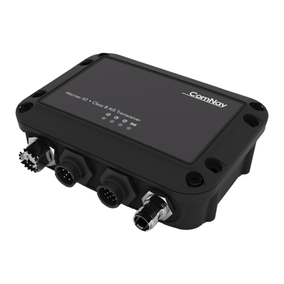
About your AIS class B transceiver Indicator lights Green Amber Blue Mounting Mounting holes holes Power and data GPS antenna NMEA 2000 VHF antenna Figure 2 AIS transceiver overview Electrical connections The AIS transceiver has the following electrical connections: • Power supply •... -
Page 12: Electrical Connections To The Ais Transceiver
About your AIS class B transceiver In addition there are two other connections for the VHF antenna and an optional external GPS antenna. Figure 3 shows an overview of the electrical connections to the AIS transceiver. AIS Class B Power in transceiver Switch NMEA0183... -
Page 13: Installation
Installation Installation Preparing for Installation Figure 4 shows a typical installation configuration for the AIS transceiver. Please take the time to familiarise yourself with the system elements and their connections prior to attempting installation. Chartplotter VHF antenna GPS antenna AIS Class B (optional) transceiver Power in... - Page 14 Installation In addition to the items provided with your AIS transceiver the following items will be required for installation: VHF antenna Connection to a suitable VHF antenna will be required for the AIS transceiver to operate. A standard marine band VHF antenna such as that used with VHF voice radios will be sufficient.
-
Page 15: Installation Procedures
Installation Connection to a PC or Mac If you choose to use a PC or Mac with suitable charting software to display received AIS messages as other vessels, this can be accomplished by connecting the USB connector on the supplied power and data cable. Installation procedures Before beginning installation of your AIS transceiver, please ensure you have the necessary additional items as detailed in section 3.1. -
Page 16: Ais Transceiver Dimensions
Installation 128 mm 42 mm 140 mm Figure 5 AIS transceiver dimensions Page 13... -
Page 17: Ais Transceiver Mounting
Installation Figure 6 AIS transceiver mounting Page 14... -
Page 18: Gps Antenna Mounting
Installation Step 2 - Installing an optional external GPS antenna For mounting of the optional external GPS antenna you will require a one inch 14 TPI thread pole. You should ensure the GPS antenna has a good clear view of the entire sky. It is not recommended that the GPS antenna is mounted up a mast where the motion of the vessel will cause the antenna to swing and potentially reduce the accuracy of the GPS position. -
Page 19: Position Of The Gps Antenna Connector
Installation Power and data GPS antenna NMEA 2000 VHF antenna Figure 8 Position of the GPS antenna connector Page 16... -
Page 20: Figure 9
Installation Step 3 - Connecting the VHF antenna Route the cable from the VHF antenna to the AIS transceiver and connect to the VHF connector on the AIS transceiver as shown in Figure 9. A standard marine band VHF antenna or AIS antenna should be used with the AIS transceiver. The connector type on the AIS transceiver is SO239. - Page 21 Installation Step 4 - Connecting the accessory cable An accessory cable is supplied with the product to provide connections to power, the external switch, the NMEA0183 data ports and USB. The cable has a pre-moulded connector at one end which should be connected to the connector on the unit marked 'PWR/DATA'. The other end of the cable has eight colour coded bare wires ready for connection and a USB connector for use with a PC or Mac.
-
Page 22: Connecting An External Switch
Installation Step 5 - Connecting an external switch A toggle switch can be connected to the AIS transceiver to provide remote control of silent mode. Connect the toggle switch between the light green and orange wires as shown in Figure 10. Connection of an external switch to toggle silent mode is optional and not essential for normal operation of the product. -
Page 23: Connecting To The Nmea0183 Data Port
Installation Step 6 - Connecting to NMEA0183 compatible equipment The two independent NMEA0183 data ports provide connection to your chart plotter and other NMEA0183 compatible equipment. Each port consists of two wires colour coded as shown in the table in Figure 11 and in the diagram in Figure 11. Connect the wires to the appropriate connections on your NMEA0183 compatible equipment. - Page 24 Installation Step 7- Connection to an NMEA2000 network (optional) The AIS transceiver can be connected to an NMEA2000 network by a suitable NMEA2000 network cable available from your local dealer. If your vessel has an NMEA2000 network please refer to the relevant documentation for your NMEA2000 equipment. Once connected, and with your chart plotter also connected to your NMEA2000 network you will be able to receive AIS targets on your chart plotter.
-
Page 25: Connecting The Power Supply
Installation Step 9 - Connecting to a power supply The AIS transceiver requires a 12V or 24V power supply typically provided by the vessel's battery. It is recommended that crimped and soldered lugs are used to connect the AIS transceiver to the power source. It is recommended that the power supply is connected via a suitable circuit breaker and/or 3A fuse block. -
Page 26: Configuring Your Ais Transceiver
Configuring your AIS transceiver Configuring your AIS transceiver Until correctly configured your AIS class B transceiver will only receive AIS messages and will not transmit AIS messages. Switching on your AIS transceiver for the first time A few seconds after power is applied to the AIS transceiver, the indicators on unit will illuminate in a pattern dependent on the configuration state of the unit. -
Page 27: Introduction To Proais2
Configuring your AIS transceiver Introduction to proAIS2 Included in the CD supplied with your product is a software tool called 'proAIS2'. proAIS2 provides the facility to configure, monitor and diagnose issues with your AIS transceiver. proAIS2 can provide assistance when ensuring that a satisfactory GPS signal is being received. -
Page 28: Operation
Operation Operation Using the AIS transceiver Once the unit has been configured it is ready for use. Providing other vessels with AIS transceivers installed are within radio range of your vessel you should see their details appear on your chart plotter or PC. These vessels will also be able to see your vessel on their chart plotter or PC. -
Page 29: Indicator Functions
Operation Indicator functions The AIS transceiver includes four coloured indicators as shown in Figure 14. The state of the indicators provides information regarding the status of the AIS transceiver. Indicator lights Green Amber Blue Figure 14 Indicator location on the AIS transceiver unit Page 26... - Page 30 Operation The meaning of typical indicator configurations is shown in the table below and Figure 14 shows the orientation of the AIS transceiver. Green indicator only The AIS transceiver is powered up, has a position fix and has transmitted at least one vessel information report.
-
Page 31: Troubleshooting
Troubleshooting Troubleshooting Issue Possible cause and remedy No data is being received by the chart plotter • Check that the power supply is connected correctly. • Check that the power supply is a 12V or 24V supply. • Check that the connections to the chart plotter are correct. No indicators are illuminated •... -
Page 32: Specifications
Specifications Specifications Parameter Value Dimensions 140 x 100 x 42 mm (L x W x H) Weight 250g Power DC (9.6V - 31.2V) Average power consumption 170mA at 12VDC Peak current rating 2A GPS Receiver (AIS Internal) 50 channel IEC 61108-1 compliant Electrical Interfaces NMEA0183 38,400kBaud output NMEA0183 4,800kBaud input... - Page 33 Specifications VHF Transceiver Transmitter x 1 Receiver x 2 (One receiver time shared between AIS and DSC) Frequency: 156.025 to 162.025 MHz in 25 kHz steps Output Power 33dBm ± 1.5 dB Channel Bandwidth 25kHz Channel Step 25kHz Modulation Modes 25kHz GMSK (AIS, TX and RX) 25kHz AFSK (DSC, RX only) Bit rate...
- Page 34 ComNav Marine Unit 15 - 13511 Crestwood Place Richmond, BC Canada, V6V 2G1 www.comnav.com 201-0233:1...
Need help?
Do you have a question about the Class B AIS and is the answer not in the manual?
Questions and answers