Table of Contents
Advertisement
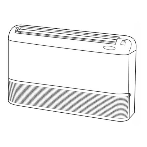
FLOOR AND CEILING TYPE AIR CONDITIONERS
SERVICE MANUAL
Wireless type
Models
MCFH-13NV-
MCFH-18NV-
MCFH-24NV-
(When installed on the floor)
(When installed on the ceiling)
• Refer to service manual OB212 for MCFH-13/18/24/NV-
MCFH-13/18/24/NV-
and MUCFH-13/18/24/NV-
E2
• Refer to service manual OB240 for MCFH-13NV-
• Refer to service manual OB185 REVISED EDITION-C for MCFH-13NV-
connected with MXZ-32NV-
• Refer to service manual OB227 REVISED EDITION-B for MCFH-13NV-
connected with MXZ-32RV-
• Refer to service manual OB254 for MCFH-13NV-
MXZ-32SV-
.
E1
• As for parts lists, all sub number's series are included.
(WH)
E4
(WH)
E3
(WH)
E3
.
E2
and MUCFH-13NV-
E3
.
E2
.
E1
or MCFH-18NV-
E4
Revision:
MUCFH-18NV-
MUCFH-18NV-
•Path of outdoor heat exchanger has changed .
•Temperature range of high pressure protection has
changed.
•Please void OB267.
·MUCFH-13NV-
·MUCFH-18NV-
·MUCFH-18NV-
·MUCFH-24NV-
CONTENTS
1. TECHNICAL CHANGES ····································2
2. PART NAMES AND FUNCTIONS······················2
3. SPECIFICATION·················································5
4. NOISE CRITERIA CURVES ·······························6
5. OUTLINES AND DIMENSIONS ·························7
6. WIRING DIAGRAM ··········································10
7. REFRIGERANT SYSTEM DIAGRAM ··············14
8. PERFORMANCE CURVES ······························16
9. MICROPROCESSOR CONTROL ····················32
10. SERVICE FUNCTIONS·····································41
11. TROUBLESHOOTING ······································42
12. DISASSEMBLY INSTRUCTIONS·····················55
13. PARTS LIST······················································63
14. OPTIONAL PARTS ······················BACK COVER
, MUCFH-13/18/24/NV-
E1
E1
.
E3
or MCFH-18NV-
E4
or MCFH-18NV-
E4
is connected with
E3
has been added.
E4
MUCFH-18NV-
E3
E4
No. OB267
REVISED EDITION-A
E4
E3
E4
E3
,
is
E3
is
E3
Advertisement
Table of Contents
Troubleshooting

Subscribe to Our Youtube Channel
Related Manuals for Mitsubishi Electric MCFH-13NV-E4


Summary of Contents for Mitsubishi Electric MCFH-13NV-E4
-
Page 1: Table Of Contents
Revision: MUCFH-18NV- has been added. MUCFH-18NV- MUCFH-18NV- •Path of outdoor heat exchanger has changed . FLOOR AND CEILING TYPE AIR CONDITIONERS •Temperature range of high pressure protection has changed. •Please void OB267. No. OB267 REVISED EDITION-A SERVICE MANUAL Wireless type Models MCFH-13NV- ·MUCFH-13NV-... -
Page 2: Technical Changes
TECHNICAL CHANGES MCFH-13NV- · MUCFH-13NV- MCFH-13NV- · MUCFH-13NV- 1. Remote controller has changed. SWING button is removed, but SWING MODE function is available by VANE CONTROL button. MCHF-18NV- · MUCFH-18NV- MCFH-18NV- · MUCFH-18NV- 1. Remote controller has changed. SWING button is removed, but SWING MODE function is available by VANE CONTROL button. MUCFH-18NV- MUCFH-18NV- 1. -
Page 3: Outdoor Unit
OUTDOOR UNIT MUCFH-13NV - Air inlet (back and side) Piping Drain hose Air outlet Drain outlet MUCFH-18NV - MUCFH-18NV - Air inlet Piping Drain hose Air outlet Drain outlet MUCFH-24NV - Air outlet Air inlet ACCESSORIES Q'ty Item MUCFH-18NV- MUCFH-24NV- MUCFH-13NV- E3 E4 Drain socket... -
Page 4: Remote Controller
MCFH-13NV - MCFH-18NV - MCFH-24NV - REMOTE CONTROLLER Signal transmitting section Operation display section OPERATE /STOP (ON /OFF)button ON/OFF WARM COOL TEMPERATURE buttons Open the front lid. CLOCK ON/OFF WARM COOL FAN SPEED CONTROL button VANE CONTROL button STOP I FEEL COOL OFF-TIMER button VANE START... -
Page 5: Specification
SPECIFICATION • Refer to service manual OB185 REVISED EDITION-C for MCFH-13NV- or MCFH-18NV- is connected with MXZ- 32NV- • Refer to service manual OB227 REVISED EDITION-B for MCFH-13NV- or MCFH-18NV- is connected with MXZ- 32RV- • Refer to service manual OB254 for MCFH-13NV- or MCFH-18NV- is connected with MXZ-32SV- MCFH-13NV-... -
Page 6: Noise Criteria Curves
NOISE CRITERIA CURVES MCFH-13NV - MUCFH-13NV - SPL(dB LINE SPEED SPL(dB LINE SPEED High 46-47 49-49 High Test conditions, Test conditions, Cooling : DB 27: WB 19:\ Cooling : DB 35: WB (24:) Heating : DB 20: WB 15: Heating : DB 7: WB 6: NC-70 NC-70 NC-60... -
Page 7: Outlines And Dimensions
MCFH-24NV - MUCFH-24NV - SPL(dB LINE SPL(dB LINE SPEED SPEED High 48-48 High 53-53 Test conditions, Test conditions, Cooling : DB 27: WB 19:\ Cooling : DB 35: WB (24:) Heating : DB 20: WB 15: Heating : DB 7: WB 6: NC-70 NC-70 NC-60... - Page 8 Unit: mm MUCFH-13NV - REQUIRED SPACE OUTDOOR UNIT Air in Outdoor unit Air in Drainage 3holes [33 Airout Service panel Liquid refrigerant pipe joint Refrigerant pipe (flared) [6.35 Gas refrigerant pipe joint Refrigerant pipe (flared) [12.7 MUCFH-18NV - MUCFH-18NV - OUTDOOR UNIT Drainage hole 16.2...
- Page 9 MUCFH-24NV - Unit: mm Outdoor Unit-Necessary surrounding clearance Air intake Note:Allow adequate upper clearance Front opening Air intake Air outlet Service space Terminal block for indoor and outdoor unit connection Outlet guide Service panel installation hole Handle for moving Handle for moving Refrigerant-pipe flared connection [15.88 Refrigerant-pipe flared...
-
Page 10: Wiring Diagram
WIRING DIAGRAM MCFH-13NV - MODEL WIRING DIAGRAM INDOOR UNIT CIRCUIT BREAKER GRN/YLW RT12 HIC1 LDCOM POWER SUPPLY LDC11 ~/N 220-240V LDC12 50Hz LDFH SR144 TRANS GRN/YLW CN201 LDFM SR143 LDFL SR142 LDFVL SR141 TO OUTDOOR 220-240V~ UNIT GRN/YLW ELECTRONIC CONTROL P.C BOARD CONNECTING 12VDC FOR MULTI SYSTEM... -
Page 11: Indoor Unit
MCFH-18NV - MODEL WIRING DIAGRAM INDOOR UNIT CIRCUIT BREAKER GRN/YLW RT12 HIC1 LDCOM POWER SUPPLY LDC11 ~/N 220-240V LDC12 50Hz LDFH SR144 TRANS GRN/YLW CN201 LDFM SR143 LDFL N BLU SR142 LDFVL TO OUTDOOR SR141 UNIT 220-240V~ GRN/YLW ELECTRONIC CONTROL P.C BOARD CONNECTING 12VDC DISP/... - Page 12 MUCFH-18NV - MODEL WIRING DIAGRAM OUTDOOR UNIT 21S4 RT61 CN730 CN661 CN721 CN720 SR61 220-240V~ TAB21 TRANS CN711 TAB20 DEICER P.C. BOARD WHT NO SYMBOL NAME SYMBOL NAME SYMBOL NAME COMPRESSOR CAPACITOR COMPRESSOR (INNER PROTECTOR) TERMINAL BLOCK OUTDOOR FAN CAPACITOR FAN MOTOR (INNER PROTECTOR) R.V.
- Page 13 MCFH-24NV - MODEL WIRING DIAGRAM INDOOR UNIT CIRCUIT BREAKER GRN/YLW RT12 HIC1 LDCOM POWER SUPPLY LDC11 ~/N 220-240V LDC12 50Hz LDFH SR144 CN201 GRN/YLW TRANS LDFM SR143 LDFL SR142 LDFVL TO OUTDOOR SR141 UNIT 220-240V~ ELECTRONIC CONTROL P.C BOARD GRN/YLW CONNECTING 12VDC DISP/...
-
Page 14: Refrigerant System Diagram
REFRIGERANT SYSTEM DIAGRAM Unit : mm MCFH-13NV- MUCFH-13NV- INDOOR UNIT OUTDOOR UNIT 4-way valve Refrigerant pipe [12.7 (with heat insulator) Muffler Stop valve Indoor (with service port) heat Outdoor Distributor Flared connection exchanger heat Strainer exchanger Coil temperature thermistor RT12 Compressor Defrost thermistor... - Page 15 Unit : mm MCFH-24NV- MUCFH-24NV- INDOOR UNIT OUTDOOR UNIT Refrigerant pipe [15.88 4-way valve (with heat insulator) Muffler Stop valve Indoor (with service port) heat Distributor Outdoor Strainer exchanger heat Flared connection exchanger Coil temperature Compressor thermistor RT12 Discharge pressure Accumulator regurator open Capillary tube...
-
Page 16: Performance Curves
PERFORMANCE CURVES MCFH-13NV - MCFH-24NV - MUCFH-13NV - MUCFH-18NV - MCFH-18NV - MUCFH-18NV - MUCFH-24NV - The standard data contained in these specifications apply only to the operation of the air conditioner under normal condition. Operating conditions vary according to the areas where these units are installed. The following information has been provided to clarify the operating characteristics of the air conditioner under the conditions indicated by the performance curve. - Page 17 20.1 25.2 29.0 18.6 23.3 26.7 17.0 21.3 24.5 15.5 19.4 22.3 13.9 17.5 20.0 12.4 15.5 17.8 10.8 13.6 15.6 11.6 13.4 OUTDOOR LOW PRESSURE AND OUTDOOR UNIT CURRENT COOL operation 1 Both indoor and outdoor units are under the same temperature/humidity condition. Dry Bulb temperature ( Relative humidity ( ˚C...
- Page 18 MUCFH-24NV- (kgf/F [Gauge]) (MPa [Gauge]) 220V 240V 220-240V 15 18 20 30 32 35(:) Ambient temperature (:) 15 18 20 30 32 35(:) Ambient humidity (%) Ambient temperature (:) Ambient humidity (%) HEAT operation Condition Indoor : Dry bulb temerature 20.0: Outdoor : Dry bulb temerature 7,15,20: Wet bulb temerature 14.5: Wet bulb temerature 6,12,14.5:...
- Page 19 PERFORMANCE DATA COOL operation(220V) MCFH-13NV - : MUCFH-13NV - CAPACITY :3.7(KW) SHF :0.72 INPUT :1310(W) OUTDOOR DB(:) INDOOR INDOOR DB(:) WB(:) SHC SHF INPUT SHC SHF INPUT SHC SHF INPUT SHC SHF INPUT 4.35 2.35 0.54 1048 4.16 2.25 0.54 1100 4.00 2.16 0.54 1153...
- Page 20 PERFORMANCE DATA COOL operation(220V) MCFH-13NV - : MUCFH-13NV - CAPACITY :3.7(KW) SHF :0.72 INPUT :1310(W) OUTDOOR DB(:) INDOOR INDOOR DB(:) WB(:) SHC SHF INPUT SHC SHF INPUT SHC SHF INPUT SHC SHF INPUT 3.63 1.96 0.54 1284 3.33 1.80 0.54 1362 3.20 1.73 0.54 1389...
- Page 21 PERFORMANCE DATA COOL operation(240V) MCFH-13NV - : MUCFH-13NV - CAPACITY :3.7(KW) SHF :0.72 INPUT :1400(W) OUTDOOR DB(:) INDOOR INDOOR DB(:) WB(:) SHC SHF INPUT SHC SHF INPUT SHC SHF INPUT SHC SHF INPUT 4.35 2.35 0.54 1120 4.16 2.25 0.54 1176 4.00 2.16 0.54 1232...
- Page 22 PERFORMANCE DATA COOL operation(240V) MCFH-13NV - : MUCFH-13NV - CAPACITY :3.7(KW) SHF :0.72 INPUT :1400(W) OUTDOOR DB(:) INDOOR INDOOR DB(:) WB(:) SHC SHF INPUT SHC SHF INPUT SHC SHF INPUT SHC SHF INPUT 3.63 1.96 0.54 1372 3.33 1.80 0.54 1456 3.20 1.73 0.54 1484...
- Page 23 PERFORMANCE DATA COOL operation(220V) MCFH-18NV - : MUCFH-18NV - MUCFH-18NV - CAPACITY :5.0(KW) SHF :0.64 INPUT :2030(W) OUTDOOR DB(:) INDOOR INDOOR DB(:) WB(:) SHC SHF INPUT SHC SHF INPUT SHC SHF INPUT SHC SHF INPUT 5.88 2.70 0.46 1624 5.63 2.59 0.46 1705 5.40 2.48 0.46 1786...
- Page 24 PERFORMANCE DATA COOL operation(220V) MCFH-18NV - : MUCFH-18NV - MUCFH-18NV - CAPACITY :5.0(KW) SHF :0.64 INPUT :2030(W) OUTDOOR DB(:) INDOOR INDOOR DB(:) WB(:) SHC SHF INPUT SHC SHF INPUT SHC SHF INPUT SHC SHF INPUT 4.90 2.25 0.46 1989 4.50 2.07 0.46 2111 4.33 1.99 0.46 2152...
- Page 25 PERFORMANCE DATA COOL operation(240V) MCFH-18NV - : MUCFH-18NV - MUCFH-18NV - CAPACITY :5.0(KW) SHF :0.64 INPUT :2120(W) OUTDOOR DB(:) INDOOR INDOOR DB(:) WB(:) SHC SHF INPUT SHC SHF INPUT SHC SHF INPUT SHC SHF INPUT 5.88 2.70 0.46 1696 5.63 2.59 0.46 1781 5.40 2.48 0.46 1866...
- Page 26 PERFORMANCE DATA COOL operation(240V) MCFH-18NV - : MUCFH-18NV - MUCFH-18NV - CAPACITY :5.0(KW) SHF :0.64 INPUT :2120(W) OUTDOOR DB(:) INDOOR INDOOR DB(:) WB(:) SHC SHF INPUT SHC SHF INPUT SHC SHF INPUT SHC SHF INPUT 4.90 2.25 0.46 2078 4.50 2.07 0.46 2205 4.33 1.99 0.46 2247...
- Page 27 PERFORMANCE DATA COOL operation(220V) MCFH-24NV - : MUCFH-24NV - CAPACITY :6.0(KW) SHF :0.64 INPUT :2720(W) OUTDOOR DB(:) INDOOR INDOOR DB(:) WB(:) SHC SHF INPUT SHC SHF INPUT SHC SHF INPUT SHC SHF INPUT 7.05 3.24 0.46 2176 6.75 3.11 0.46 2285 6.48 2.98 0.46 2394...
- Page 28 PERFORMANCE DATA COOL operation(220V) MCFH-24NV - : MUCFH-24NV - CAPACITY :6.0(KW) SHF :0.64 INPUT :2720(W) OUTDOOR DB(:) INDOOR INDOOR DB(:) WB(:) SHC SHF INPUT SHC SHF INPUT SHC SHF INPUT SHC SHF INPUT 5.88 2.70 0.46 2666 5.40 2.48 0.46 2829 5.19 2.39 0.46 2883...
- Page 29 PERFORMANCE DATA COOL operation(240V) MCFH-24NV - : MUCFH-24NV - CAPACITY :6.0(KW) SHF :0.64 INPUT :2750(W) OUTDOOR DB(:) INDOOR INDOOR DB(:) WB(:) SHC SHF INPUT SHC SHF INPUT SHC SHF INPUT SHC SHF INPUT 7.05 3.24 0.46 2200 6.75 3.11 0.46 2310 6.48 2.98 0.46 2420...
- Page 30 PERFORMANCE DATA COOL operation(240V) MCFH-24NV - : MUCFH-24NV - CAPACITY :6.0(KW) SHF :0.64 INPUT :2750(W) OUTDOOR DB(:) INDOOR INDOOR DB(:) WB(:) SHC SHF INPUT SHC SHF INPUT SHC SHF INPUT SHC SHF INPUT 5.88 2.70 0.46 2695 5.40 2.48 0.46 2860 5.19 2.39 0.46 2915...
- Page 31 PERFORMANCE DATA HEAT operation(220V) MCFH-13NV - : MUCFH-13NV - CAPACITY :4.0(KW) INPUT :1130(W) OUTDOOR WB(:) INDOOR DB(:) INPUT INPUT INPUT INPUT INPUT INPUT INPUT 2.52 3.04 3.56 4.08 1074 4.60 1141 5.08 1175 5.60 1198 2.40 2.88 3.40 1040 3.88 1119 4.40 1175...
-
Page 32: Microprocessor Control
MICROPROCESSOR CONTROL MCFH-13NV - MCFH-24NV - MUCFH-13NV - MUCFH-18NV - MCFH-18NV - MUCFH-18NV - MUCFH-24NV - Once the operation mode are set, the same operation mode WIRELESS REMOTE CONTROLLER can be repeated by simply turning the OPERATE/STOP(ON/OFF) button ON. Signal transmitting section Indoor unit receives the signal with a beep tone. -
Page 33: High
(4) The initial set temperature is decided by the initial room temperature. Initial room temperature Initial set temperature Model 26: or more COOL mode of "I FEEL CONTROL" Initial room temperature 25: to 26: minus 2: Initial room temperature DRY mode of 23: to 25: "I FEEL CONTROL"... -
Page 34: High
3. Outdoor fan control <MUCFH-24NV - > Ambient temperature Outdoor fan speed is controlled according to the temperature of ambient temperature thermistor RT63 temperature thermistor RT63. Outdoor fan Low operation : When the outside temperature decreases to 28.5°C or less. Outdoor fan speed High Until when the outside temperature goes to 31°C. - Page 35 (2) Cold air prevention control The fan runs at set speed when the indoor coil thermistor RT12 temperature exceeds 22°C. The fan operates at Very Low when the temperature of indoor coil thermistor RT12 is below 18°C. But the fan stops when the indoor fan operates at Very Low and the room temperature is 15°C or less.
- Page 36 4. Defrosting Defrosting of outdoor heat exchanger is controlled by DEICER P.C. board, with detection by the defrost thermistor RT61. (1) Starting conditions of defrost When all conditions of a) ~ c) are satisfied, the defrosting operation starts. a) The compressor cumulative operation time exceeds 40 minutes without the defrosting operation working. b) The defrost thermistor RT61 reads - 3°C or less.
- Page 37 5. R.V. coil control Heating · · · · · ON Cooling · · · · · OFF Dry · · · · · · · · OFF NOTE1. : • The 4-way valve reverses for 5 seconds right before start-up of the compressor. NOTE2.
- Page 38 9-5. AUTO VANE OPERATION (1) Vane motor drive This series is equipped with a stepping motor for the vane. The rotating direction, speed, and angle of the motor are controlled by pulse signals (approx. 12V) transmitted from indoor microprocessor. (2) Each time the VANE CONTROL button is pressed, angle of horizontal vane is changed in sequence, from 1, 2, 3, 4, 5 SWING to AUTO.
-
Page 39: Program Timer
(8) Cold air prevention in HEAT operation. When any of the following conditions occurs in HEAT operation, the angle of horizontal vane automatically changes to Position 1 to prevent cold air blowing on users. 1 Compressor is not operating. 2 Defrosting is performed. 3 Indoor coil thermistor RT12 reads 24: or below. - Page 40 9-7. EMERGENCY-TEST OPERATION In case of test run operation or emergency operation, use the EMERGENCY OPERATION switch on the front of the indoor unit. Emergency operation is available when the remote controller is missing, has failed or the batteries of remote controller run down.
-
Page 41: Service Functions
SERVICE FUNCTIONS MCFH-13NV - MCFH-24NV - MUCFH-13NV - MUCFH-18NV - MCFH-18NV - MUCFH-18NV - MUCFH-24NV - 10-1. COMPULSORY DEFROSTING MODE FOR SERVICE By short circuit of the connector JP607 and R853 (MUCFH-13/18NV) / JPG1 and R871 (MUCFH-24NV) on the outdoor deicer P.C. -
Page 42: Troubleshooting
10-5. RELEASE OF AUTO RESTART FUNCTION Solder JHA (refer to page 52) with a jumper line on the indoor electronic control P.C. board. Remove the auto restart assy from “Connector CN104”. TROUBLESHOOTING MCFH-13NV - MCFH-24NV - MUCFH-13NV - MUCFH-18NV - MCFH-18NV - MUCFH-18NV - MUCFH-24NV -... - Page 43 11-2. Instruction of troubleshooting Start Indoor unit Indoor unit Indoor unit operates. OPERATION INDICATOR operates. doesn't receive Outdoor unit lamp on the indoor unit is Outdoor unit the signal from doesn't operate flashing on and off. doesn't remote controller. normally. operate.
-
Page 44: Troubleshooting Check Table
1. Troubleshooting check table OPERATION INDICATOR lamp Before taking measures, make sure that the symptom reappears, for accurate troubleshooting. Self check table Abnormal Indication Symptom Detect method Check point point 0.5-second ON When serial signal stops for 4 to 5 seconds after 1st on of Mis-wiring 52C contactor by POWER turning on. - Page 45 2. Trouble criterion of main parts MCFH-13NV - MCFH-24NV - MUCFH-13NV - MUCFH-18NV - MCFH-18NV - MUCFH-18NV - MUCFH-24NV - Part name Check method and criterion Figure Room Measure the resistance with a tester. temperature (Part temperature 10°C ~ 30°C) thermistor (RT11) Normal Abnormal...
-
Page 46: Check Of Indoor Fan Motor
Indoor fan does not operate. Check of indoor fan motor Turn OFF power supply. Check connector (Fan motor) visually. Is soldered point of the connector Are lead wires connected? correctly soldered? Re-connect the lead Re-solder it. wires. Disconnect lead wires from connector (Fan motor). Measure resistance between lead wires No.1 and No.4 and then No.3 and No.4 of the fan motor. -
Page 47: Check Of Indoor Electronic Control P.c. Board
The unit does not operate with the remote controller. Also, the OPERATION INDICATOR lamp doesn’t light up by pressing the EMERGENCY OPERATION switch. Check of indoor electronic control P.C. board Replace the fuse. Is fuse(F11)blown? Trouble of the indoor electronic Be sure to check both fuse Check both “parts side”and “pattern control P.C. - Page 48 Compressor and outdoor fan does not operate. Check of outdoor unit MCFH-24NV - Start Operate the unit in COOL or HEAT mode by pressing the EMERGENCY OPERATION switch. 3-minute time delay works. Test run operation operates for 30 minutes. Compressor doesn't operate.
- Page 49 When OPERATION INDICATOR lamp flashes ON and OFF in every 0.5-second or flashes once. Outdoor unit does not operate. How to check mis-wiring and serial signal error (when outdoor unit does not work) Start w 1 Short circuit of JPG and JPS on the 1.
- Page 50 Compressor and / or outdoor fan motor does not stop. Check of outdoor unit 1 Turn OFF the power supply. 2 After 30 seconds, turn ON the power supply again. 3 Operate the unit in COOL or HEAT mode by pressing the EMERGENCY OPERATION switch.
-
Page 51: Check Of Outdoor Thermistor
When OPERATION INDICATOR lamp flashes 6-time. Thermistors in the outdoor unit are abnormal. Check of outdoor thermistor w Disconnect the connectors CN661 and/or CN662 from the deicer P.C. board. (Check the characteristics of each thermistor.) Defrost thermistor(RT61) Measure resistance between CN 661 1 and 2. - Page 52 TEST POINT DIAGRAM AND VOLTAGE MCFH-13NV - MCFH-18NV - MCFH-24NV - Indoor electronic control P.C. board Fan motor power supply 220 - 240V AC Very Med. High Fuse (F11) 250V AC 3.15A Power supply input 220-240V AC 12V DC – 5V DC –...
- Page 53 MUCFH-13NV - MUCFH-18NV - MUCFH-18NV - Outdoor deicer P.C. board Fan motor R601 Power supply R.V. coil (CN711) 5~10V DC input (CN721) 220-240V AC 220-240V AC 220-240V AC Defrost thermistor(RT61) DEICER P.C. BOARD Fuse (F61) 2A/250V Defrost interval time short pin (JP607, R853) (Refer to page 41) 5V DC...
- Page 54 MUCFH-24NV - Outdoor deicer P.C. board Defrost thermistor (RT61) Ambient temperature thermistor (RT63) -20 -10 10 20 30 40 Temperature(:) CN661 1-2 CN662 3-4 Defrost ther- Ambient tempera- Fan motor mistor (RT61) ture thermistor Varistor (CN711) (RT63) (NR62) 220-240V R.V. coil (CN721) 220-240V Defrost...
-
Page 55: Disassembly Instructions
DISASSEMBLY INSTRUCTIONS “w” shows the terminals with a lock mechanism, so they cannot be removed when you pull the lead wire. 1Slide the sleeve. Be sure to pull the wire by pushing the locking 2Pull the wire while pushing the locking lever. lever (project part) of the terminal with a finger. - Page 56 OPERATING PROCEDURE PHOTOS 3. Removing the indoor heat exchanger. Photo 5 (1) Remove the grill. (Refer to 1(1) (2)) (2) Remove the screws on both side and in front of the front panel. (Photo 5) (3) Remove the screws of the nozzle assembly. (Photo 6) (4) Remove the electronic box .
- Page 57 12-2. MUCFH-13NV - OUTDOOR UNIT OPERATING PROCEDURE PHOTOS 1. Removing the cabinet Photo 1 Screws of the front panel (1) Remove the screws of the top panel. and motor support (2) Remove the screws of the service panel. (3) Remove the screws of the cabinet. (4) Remove the screws of the front panel and motor support.
- Page 58 OPERATING PROCEDURE PHOTOS 3. Removing the propeller fan and the outdoor fan Photo 5 motor Lead clamps Set screws of the (1) Remove the cabinet. (Refer to 1) outdoor fan motor Hook (2) Remove the propeller fan nut. Outdoor (3) Remove the propeller fan. fan motor Propeller fan NOTE : Loose the propeller fan in the rotating direction for...
- Page 59 12-3. MUCFH-18NV - MUCFH-18NV - OUTDOOR UNIT OPERATING PROCEDURE PHOTOS 1. Removing the cabinet Photo 1 (1) Remove the screws of the cabinet. (2) Hold the bottom of the cabinet on the both side to remove the cabinet. Photo 2 Screws Service panel...
- Page 60 OPERATING PROCEDURE PHOTOS Photo 4 3. Removing the outdoor fan motor Set screws of the (1) Remove the cabinet. (Refer to 1) outdoor fan motor Lead clamps propeller fan (2) Disconnect the connector remove the clamp of fan motor lead wire. (3) Remove the propeller fan nut and remove the propeller fan.
- Page 61 12-4. MUCFH-24NV - OUTDOOR UNIT OPERATING PROCEDURE PHOTOS 1. Removing the cabinet Photo 1 (1) Remove the screws of the top panel and the top panel. (2) Remove the screw of the service panel. To remove the Screws service panel, pull it down toward you and unhook the Top panel catches on the both sides.
- Page 62 OPERATING PROCEDURE PHOTOS 4. Removing the heat exchanger and compressor Photo 4 (1) Remove the screws of the rear panel. Remove the screws of the valve bed and the valve bed. (The valve bed is Screws fixed by the catches on the right and left sides. Lift it to remove.) Open the rear panel to the rear to remove.
-
Page 63: Parts List
PARTS LIST 13-1. INDOOR UNIT STRUCTURAL PARTS MCFH-13NV - (WH) MCFH-13NV - (WH) MCFH-13NV - (WH) MCFH-13NV - (WH) MCFH-18NV - (WH) MCFH-18NV - (WH) MCFH-18NV - (WH) MCFH-24NV - (WH) MCFH-24NV - (WH) MCFH-24NV - (WH) Part number that is circled is not shown in the illustration. Q'ty/unit MCFH- Symbol... -
Page 64: Electrical Parts
MCFH-13NV - (WH) MCFH-13NV - (WH) MCFH-13NV - (WH) MCFH-13NV - (WH) MCFH-18NV - (WH) MCFH-18NV - (WH) MCFH-18NV - (WH) MCFH-24NV - (WH) MCFH-24NV - (WH) MCFH-24NV - (WH) 13-2. INDOOR UNIT 13-3. ACCESSORY AND ELECTRICAL PARTS REMOTE CONTROLLER 13NV- 13NV- 18NV-... - Page 65 13-4. OUTDOOR UNIT STRUCTURAL PARTS MUCFH-13NV - MUCFH-13NV - Part number that is circled is not shown in the illustration. Q'ty/unit Symbol in Wiring Remarks Part No. Part name MUCFH- MUCFH- Diagram 13NV- 13NV- E02 442 630 OUTDOOR HEAT EXCHANGER E02 336 232 CABINET E02 336 521...
- Page 66 MUCFH-13NV - MUCFH-13NV - 13-6. ACCESSORY 13-5. OUTDOOR UNIT ELECTRICAL PARTS AND FUNCTIONAL PARTS 13-5. OUTDOOR UNIT ELECTRICAL PARTS AND FUNCTIONAL PARTS Part numbers that are circled are not shown in the illustration. Q'ty/unit Symbol in Wiring Remarks Part name MUCFH- MUCFH- Part No.
- Page 67 MUCFH-13NV- MUCFH-13NV- MUCFH-18NV- MUCFH-18NV- MUCFH-18NV- MUCFH-18NV- 13-8. ACCESSORY 13-7. OUTDOOR UNIT STRUCTURAL PARTS 13-7. OUTDOOR UNIT STRUCTURAL PARTS Part numbers that are circled are not shown in the illustration. Q'ty/unit Symbol MUCFH in Wiring Part No. Part name Remarks 13NV- 18NV- Diagram E02 141 232...
- Page 68 MUCFH-24NV- MUCFH-24NV- 13-9. OUTDOOR UNIT STRUCTURAL PARTS 13-10. ACCESSORY...
- Page 69 MUCFH-24NV- MUCFH-24NV- 13-9. OUTDOOR UNIT STRUCTURAL PARTS Part numbesr that are circled are not shown in the illustration. Q'ty/unit Symbol Remarks Part No. Part Name in Wiring MUCFH-24NV- MUCFH-24NV- Diagram E02 214 249 SIDE PANEL E02 214 232 CABINET E02 214 521 FAN GURD E02 214 290 BASE...
- Page 70 MUCFH-24NV- 13-11. OUTDOOR UNIT STRUCTURAL PARTS 13-12. ACCESSORY...
- Page 71 MUCFH-24NV- 13-11. OUTDOOR UNIT STRUCTURAL PARTS Part numbers that are circled are not shown in the illustration. Q'ty/unit Symbol in Wiring Part No. Part Name Remarks MUCFH-24NV- Diagram E02 214 297 TOP PANEL RT63 E02 540 309 AMBIENT TEMPERATURE THERMISTOR E02 444 961 4-WAY VALVE 21S4...
-
Page 72: Optional Parts
MAC - 1700 DF MCFH - 24NV- HEAD OFFICE: MITSUBISHI DENKI BLDG.,2-2-3, MARUNOUCHI, CHIYODA-KU, TOKYO100-8310, JAPAN C C Copyright 2001 MITSUBISHI ELECTRIC ENGINEERING CO.,LTD Distributed in Dec. 2001. No.OB267 REVISED EDITION-A 247 New publication, effective Dec. 2001 Distributed in Mar. 2001. No.OB267 248 Specifications subject to change without notice.
Need help?
Do you have a question about the MCFH-13NV-E4 and is the answer not in the manual?
Questions and answers