Advertisement
Table of Contents
- 1 Important Safety Instructions
- 2 Hardware Installation
- 3 Safety Precautions
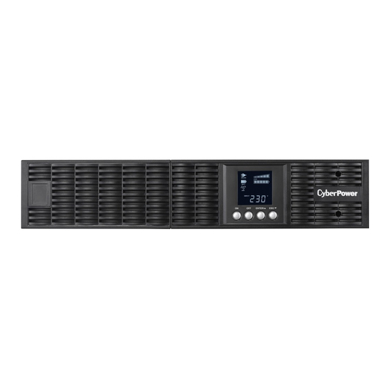
- 4 Rack Mount Installation
- 5 Vertical/Tower Installation
- 6 Electrical Installation
- 7 System Block Diagram
- 8 Installing Your Ups System
- 9 Basic Operation
- 10 Button Operation
- 11 Lcd Setup Functions
- 12 Silencing Audible Alarms
- 13 Manual Battery Test
- 14 Maintenance
- 15 Technical Specifications
- 16 Troubleshooting
- Download this manual
Advertisement
Table of Contents


Need help?
Do you have a question about the OLS1000ERT2U and is the answer not in the manual?
Questions and answers