Table of Contents
Advertisement
Quick Links
Advertisement
Table of Contents

Subscribe to Our Youtube Channel
Related Manuals for SEAL IMAGE 80S


Summary of Contents for SEAL IMAGE 80S
- Page 1 Owner’s manual IMAGE 80S...
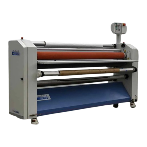
- Page 3 Foreword We would like to thank you for purchasing the IMAGE 80S laminating machine, a laminating machine designed to give you many years of reliable use. The IMAGE 80S is easy to use and will produce a high quality end result.
-
Page 5: Table Of Contents
Contents INTRODUCTION Installation Information ..............7 Unpacking the Laminator ..............7 Laminator Identification ................9 Environmental Conditions ..............10 Working area..................11 Description of the Laminator ............13 Identification of Parts................13 Safety and warranty information ............17 Warnings....................18 Safety Features..................20 Control Panel Information ..............25 Control Panel Overview................25 Control Panel Functions ...............27 Using the foot pedal ................36 ®... - Page 6 ® LIMITED WARRANTY ON IMAGE LAMINATORS Hunt Graphics warrant to the original consumer purchaser that all new ® ® Image laminators that prove defective in materials or workmanship within the applicable warranty period will be repaired or, at our option, replaced without charge. The applicable warranty shall be one year from date of purchase with the exception of silicone roll coverings that will be six months from date of purchase.
-
Page 7: Introduction
LIABILITY The details given in this manual are based on the most recent information available to They may be subject to change in the future. We retain the right to make changes to the construction or the design of our products without accepting any responsibility for modifying laminators previously delivered. - Page 8 Symbols used in this owner’s manual Pay extra attention to the passages marked with this symbol. This information is particularly important for the operation and ® maintenance of the IMAGE 80S. Passages marked this way offer an idea/tip or offer information on the efficient use of the laminator Before operating the laminator for the first time, read through the Owner’...
-
Page 9: Installation Information
Installation information UNPACKING, SET-UP AND INSTALLATION MUST BE PERFORMED BY TRAINED PERSONNEL. ® The IMAGE 80S is delivered on a pallet and is packaged in plastic to prevent moisture penetration. A cardboard box is placed over the plastic. For unpacking, location and installation, follow the instructions in the manual. Unpacking the Laminator Unpack the laminator in the order of the following steps, which correspond to the numbers in Figure 1. - Page 10 Remove the wooden blocks (3) from beneath the outer edges of the cabinets which the transport bolts pass through. Turn the support blocks under the laminator to allow the laminator to be rolled off the pallet. Screw the adjustable feet upwards, so that the laminator is supported on its moveable castor wheels.
-
Page 11: Laminator Identification
Check that your power supply voltage is the same as the voltage stated on the type plate (see paragraph III, in the installation manual). Insert the plug in the power supply socket and the machine is ready for use. When the main switch is set to ON, the upper roller will move automatically to the upper position. -
Page 12: Environmental Conditions
Environmental Conditions Specific environmental conditions are ideal for the best operation of the laminator. Temperature ® The best temperature for the IMAGE 80S is between 10°C and 35°C (50°F and 95°F). Do not expose the laminator to direct sunlight as output quality may be affected. Relative humidity ®... -
Page 13: Working Area
Working area The machine needs a working area that is at least as wide as the machine plus 60 cm (23.6 in) on both sides. The space required at the front and back of the laminator must be large enough to easily handle the maximum board length (see Figure 4). Figure 4 ®... - Page 14 ® Owner’s manual IMAGE...
-
Page 15: Description Of The Laminator
Description of the Laminator ® The IMAGE 80S is a mounting and laminating machine with a working width of 200cm (78.7 in). ® The IMAGE 80S is provided with variable settings for: • the opening between the rollers (the nip) •... - Page 16 No. Part name Description Digital control panel Controls for operating the laminator and displays for the temperature, speeds and nip setting. The control panel is mounted on an arm so that the laminator can be operated from any point around the laminator. Feed table The in-feed table used for material input, flips up to allow for easy webbing.
- Page 17 Figure 6 ® Owner’s manual IMAGE...
- Page 18 No. Part name Description Tape dispenser A holder for adhesive tape beneficial for securing release liners to take-up shafts and other purposes. Photoelectric cells These are fitted on the front and rear sides of the rollers. If the beam is interrupted, the laminator will stop running immediately.
-
Page 19: Safety And Warranty Information
Safety and warranty information ® The IMAGE 80S is designed with safety and protective devices with the user’ s safety of utmost consideration. However, following safe operating guidelines is still the responsibility of the operator. Hunt Graphics Europe B.V. has taken every precaution to provide you with correct information concerning all risks connected with the operation of the laminator. -
Page 20: Warnings
SERVICING AND REPLACEMENT PARTS Service and maintenance must be performed fully in accordance with the instructions. Servicing by any unauthorized technician voids the warranty. The service technician must use replacement parts specified by Hunt Graphics. Call Technical Service for assistance (see rear cover for the location nearest you.) Service technicians must perform safety checks after completing any service or repairs to the laminator. - Page 21 ® Owner’s manual IMAGE...
-
Page 22: Safety Features
Safety Features Photoelectric Safety Eyes Because the machine can run continuously at high speed in both directions, photoelectric eyes are mounted on both sides of the roller opening. The laminator stops if one of these eyes is interrupted. For example, if a panel is thicker than the pre-set nip value or if someone puts a hand into the nip opening. - Page 23 Safety Cord Switch As an additional safety precaution, a safety cord the length of the laminator is attached to the front (see Figures 13 and 14). The safety cord can be operated with the foot and like the emergency stop buttons;...
- Page 24 During the slow mode, the photoelectric-eyes are not operational. Main Switch The main switch (see Figure 16) is mounted on the right side cabinet door. This switch has two positions; ON (laminator on); OFF (laminator off); The switch can be secured with a padlock in the OFF position to Figure 16 prevent any unauthorized operation of the laminator.
- Page 25 The rollers and the auto-grip shafts will stop if: • The stop push button on the control panel is pressed. • One of the emergency stop buttons is pressed. • The safety cord on the front of the laminator is activated (emergency stop circuit).
- Page 26 ® Owner’s manual IMAGE...
-
Page 27: Control Panel Information
Control Panel Information This section describes the control panel, which consists of various push buttons, a rotating knob, LED’ s and displays. An overview of the control panel functions is provided, together with drawings of the control buttons and an explanation of the associated symbols. - Page 28 segment segment segment segment Figure 19 Figure 19 provides an overview of the complete control panel, which consist of four segments: First segment This segment contains a display, selection keys, and a rotating knob for setting the roller speed. Second segment The keys in the second segment are used for setting the nip (the opening between the rollers).
-
Page 29: Control Panel Functions
Control Panel Functions First segment The speed of the rollers is continuously adjustable between 0 and 5m/min. (0 and 16.5 ft/min). Pressing the key runs the rollers in the forward, while pressing the reverses the direction of the rollers. The stop key stops the roller movemen. The 3-digit display shows the roller speed. - Page 30 In this section, the functions of the symbols for each segment are presented in table form. The first column shows the function key, while the second column gives a description of the key and the third column described the key function. Speed display Figure 20 Figure 20 shows an overview of the first segment of the control panel, used for setting...
- Page 31 Button/key/display Description Function Stop key Stops the rotation of the rollers. Display for roller speed, Displays the roller speed in m/min or ft/min. emergency stop, photo- The roller speed can be pre-set. eyes or error message. Forward roller direction The rollers rotate in the forward direction. Reverse roller direction The rollers rotate in the reverse direction.
- Page 32 The rollers will stop rotating if: • The photocells are interrupted; • One of the emergency stop buttons is pressed; • The foot pedal is pressed momentarily; • The feed table is raised; • The machine is too heavily loaded, so that the motor thermal cut-out operates. Reset by switching the main switch off and on again.
- Page 33 Nip setting Figure 21 Figure 21 shows the second segment of the control panel. These keys adjust the distance between the rollers (= the nip setting). Always adjust the nip setting to the thickness of the board! Key/display Description Function Nip opening display (or The display indicates the gap between the error message).
- Page 34 The up and down movement of the upper roller can be interrupted by entering a new nip setting, interrupting the photo-eyes or by pressing an emergency stop. Ensure that the upper roller is in the uppermost position before switching off the machine to avoid getting flat spots on the rollers.
- Page 35 Roller pressure setting Figure 22 The third segment of the display is used to set the roller pressure. This roller pressure can be set to values between 0.75 N/mm and 1.6 N/mm. The roller pressure is shown in the corresponding 3-digit display on the control panel. This function enables different material widths to be processed with the correct pressure.
- Page 36 Roller temperature Figure 23 The fourth segment of the control panel is used for regulating the roller temperature. The temperature of the upper roller can be continuously adjusted to any desired temperature between 40°C (100°F) and 130°C (266°F). The temperature setting is shown in the corresponding 3-digit display on the control panel.
- Page 37 Key/display Description Function Display of temperature The display shows the actual roller setting (or error temperature. When the key is pressed, the message) The LED in temperature setting is displayed the lower right-hand corner flashes during the heating cycle and remains lit when the set temperature is reached.
-
Page 38: Using The Foot Pedal
Using the foot pedal The function of the foot pedal is to permit the rotation of the rollers to be controlled in a hands-off manner. When the speed has been set on the control panel and the safety photo-eyes are not interrupted, the rotation of the rollers can be started by operating the foot pedal. - Page 39 Take the following steps to switch over from normal speed to the slow mode without stopping the laminator; (This will prevent stop marks appearing in the material) • Operating in slow mode combined with using the foot pedal, Press and hold the roller direction forward key, without releasing the foot pedal;...
- Page 40 ® Owner’s manual IMAGE...
-
Page 41: Set-Up And Operating Of The Image 80S
® Set-up and operating of the IMAGE ® This section contains instructions for the set-up and operation of the IMAGE 80S. This includes processes for pre-coating boards, creating a decal (sticker), board mounting, etc. You can perform the above mentioned processes in different ways as outlined in the next paragraphs. - Page 42 Take care that the ends of the shaft do not become damaged during the loading and unloading of the laminator Step 3 Place the shaft holding the roll of laminate back into the laminator by inserting it in the supply shaft holders and rotate it until it clicks.
-
Page 43: Pre-Coating Boards
Pre-Coating Boards This is the first step of the 3-Step Process. This process is used to coat substrates with a pressure-sensitive mounting adhesive onto which images can be mounted. This same process is used to create a carrier board or sled (see glossary of laminating terms). - Page 44 Step 5 After the last image and the ending leader board pass through the rollers, carefully cut off the laminate between the supply shaft and top roller using an enclosed blade cutter (see Figures 34 and 35). Figure 34 Figure 35 Never cut the foil with an ordinary knife or a Stanley knife.
-
Page 45: Mounting Images To Pre-Coated Boards
Mounting Images to Pre-coated Boards This is the second step in the 3-step process. Step 1 Fold back approximately 25 mm (1 inch) of the release liner along one of the edges of the adhesive coated board. Crease the release paper evenly on this fold, pressing with your fingertips from the center out. -
Page 46: Applying An Over-Laminate To A Mounted Image
The board with the final edge of the image is being processed (see Figure 40). Figure 40 Always work in the centre of the machine! Applying an Over-Laminate to a Mounted Image After mounting the image to a board, a protective laminate can be applied. The over-laminate can be a heat-activated laminate or a pressure-sensitive adhesive with a release liner. - Page 47 Step 5 Drape the self-adhesive laminate over the upper roller, so that the leader board takes the laminate in with it when it is inserted into the nip opening. Step 6 Place the leader board in the correct position and push the board, together with the Figure 42 laminate, into the nip opening.
-
Page 48: Decaling
Decaling This process involves sandwiching an image between either a hot or cold laminate on the front of the image and a pressure-sensitive mounting adhesive on the back. They can later be mounted onto a board or other substrate. This is the first step of the 2-Step Process. Check that both the laminates are the same width to prevent adhesive from getting on the rollers.. - Page 49 Step 2 Flip the feed table up to allow for easier webbing. Step 3 Pull the laminate upward from the lower supply shaft È (reduce the brake tension if necessary) and place it over the lower roller Ã. Stick the self- adhesive laminate to the protective laminate draped over the upper roller (see Figure 45).
- Page 50 Step 6 Attach the image guide onto the in-feed table to simplify the feeding of the image into the nip (see Figure 47). Afbeelding 47 Step 7 The laminator is now ready for the image to be fed in (see Figure 48). Note.
-
Page 51: Mounting Laminated Decals
Mounting Laminated Decals This process uses a previously processed image with an adhesive coating on the back and a protective over-laminate on the front. This is the second step of the 2-Step Process. Step 1 Place the board to which the image will be mounted on a flat surface. Lay the image that is to be mounted face down on the board and fold back approximately 25 mm (1”) of the protective paper backing over the full width. - Page 52 Step 6 Drape the image back over the upper guide shaft (see Figure 49). Remove the release liner partially and press the foot pedal to feed the panel through the laminator. The control panel may now be used to take over the feed if desired.
-
Page 53: Cleaning And Maintenance
Cleaning and maintenance ® Cleaning the IMAGE Do not use abrasive materials for cleaning the laminator. This can damage the painted surfaces or the rubber covering of the rollers. For cleaning, only use a damp cloth. Ensure that water does not run into any of the cabinets. -
Page 54: Maintenance Of The Image 80S
® Maintenance of the IMAGE ® The IMAGE 80S requires little maintenance and only the following is required: • Lubricate both of the roller raising worm wheels in the left-hand cabinet with a molykote (thick grease) twice per year. • Wipe the feed table with a dry cloth as needed. -
Page 55: Troubleshooting
Troubleshooting The following table provides some possible solutions for a number of problems that can occur when using the laminator. Problem Solution • The display is blank. Check that the laminator is connected to the mains; • Check that the main switch is ON. •... - Page 56 Error messages in Cause Solution the display Emergency push button Reset the emergency stop on boxes of control panel pressed. Reset the emergency stop cord Emergency stop cord by pressing the blue push button operated. on the front of the laminator. Feed-in table not in the lowest position.
-
Page 57: Appendices
APPENDICES • Technical specification IMAGE 80S • Accessories • Temperature / Speed table ® Owner’s manual IMAGE... -
Page 58: Accessories
Accessories The following items are supplied with the machine: • Owner’s manual • Quick reference guide • Enclosed blade cutter • Rubber cleaning block for the rollers • Spare fuses (in a bag inside the machine) • Set of open-ended wrenches •... -
Page 59: Speed / Pressure / Temperature Settings
Speed / Pressure / Temperature settings For the materials listed below, the following variables can be set: SEAL material Speed Pressure Temperature Brake tension Print Shield 2 m/min. 0.9 - 1.0 Environment to Light standard / Pro 6.5 ft/min 50 ºC (122 ºF) -
Page 60: Process Fault Diagrams
Process Fault Diagrams Figure 52 When the picture displays this pattern, the pressure is too high. Figure 53 When the picture displays this pattern, the pressure is too low. The ideal pressure line is 1N/mm when the full width of the material is used. If there are problems with the use of materials, contact your supplier. -
Page 61: Glossary Of Laminating Terms
GLOSSARY OF LAMINATING TERMS ECAL An image that has been laminated on top (either heat-activated or pressure-sensitive) with an adhesive backing. CTIVATED AMINATES Laminates with a dry adhesive that is activated when heat is applied. Once applied to an image the adhesive forms a strong bond locking the laminate and the image together. FEED The side of the laminator from which images are fed. -
Page 62: Technical Specifications
® Technical specification for the IMAGE Connection for single-phase power supply 200-250V ±10% 50/60 Hz 25 A Connection for three-phase power supply 3N/PE 200-250V ±10% 50/60 HZ 25 A Data display 4 x 3-digit 7-segment displays Material supply capacity 1 foot (30 cm) (average roll) Material take-up capacity shafts 7 inches (18 cm)
Need help?
Do you have a question about the IMAGE 80S and is the answer not in the manual?
Questions and answers