Advertisement
Quick Links
Effective : June, 2002
SERVICE MANUAL
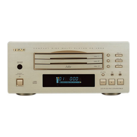
P P D D - - H H 5 5 0 0 3 3
CONTENTS
1 SPECIFICATIONS
2 EXPLODED VIEWS AND PARTS LIST
3 PC BOARDS AND PARTS LIST
4 INCLUDED ACCESSORIES
PC boards shown are viewed from parts side.
The parts with no reference number or no parts number in the
exploded views are not supplied.
As regards the resistors and capacitors, refer to the circuit diagrams
contained in this manual.
Parts marked with this sign are safety critical components. They
£
must be replaced with identical components - refer to the appropriate
parts list and ensure exact replacement.
Parts of [ ] mark can be used only with the version designated.
3CD Player
NOTES
S-0066A
2
3
8
10
Advertisement

Related Manuals for Teac PD-H503


Summary of Contents for Teac PD-H503
- Page 1 SERVICE MANUAL P P D D - - H H 5 5 0 0 3 3 3CD Player CONTENTS 1 SPECIFICATIONS 2 EXPLODED VIEWS AND PARTS LIST 3 PC BOARDS AND PARTS LIST 4 INCLUDED ACCESSORIES NOTES PC boards shown are viewed from parts side. The parts with no reference number or no parts number in the exploded views are not supplied.
-
Page 2: Specifications
1 SPECIFICATIONS Laser System Power supply 3-beam laser 120 V AC, 60Hz (U.S.A./Canada Model) Digital Filter 230 V AC, 50Hz (Europe/U.K. Model) 8-times oversampling Power consumption Frequency response 12 W 20Hz ~ 20kHz (playback: ±0.5dB) Dimensions (W x H x D) Signal to noise ratio 285 x 131 x 327 mm (11-1/4"... -
Page 3: Exploded Views And Parts List
2 EXPLODED VIEWS AND PARTS LIST EXPLODED VIEW-1... - Page 4 EXPLODED VIEW-1 £ £ £ £ £ £...
- Page 5 EXPLODED VIEW-2 ø ∑ ª ∑ ∑ ∑ ∑ œ & ∑ ∞ œ œ ¡ † † œ œ ® œ § œ œ ¢ ∞ œ œ ´ < å π ˆ ´ º > ™ < ∞ ¨...
- Page 6 EXPLODED VIEW-2 (MGC-F3400)
- Page 7 EXPLODED VIEW-2 (MGC-F3400)
-
Page 8: Pc Boards And Parts List
3 PC BOARDS AND PARTS LIST MAIN PCB POWER PCB FRONT PCB... - Page 9 MAIN PCB ASSY (GATHER) FRONT PCB ASSY MAIN PCB ASSY POWER PCB ASSY £ £ £ £ £ £ £ £ £ £ £ £ £ £ £ £ £ £...
-
Page 10: Included Accessories
4 INCLUDED ACCESSORIES INCLUDED ACCESSORIES... - Page 11 PD-H503 BLOCK DIAGRAM P P D D - - H H 5 5 0 0 3 3 3CD Player 1 st Issue; May 2002...
- Page 12 PD-H503 WIRING DIAGRAM P P D D - - H H 5 5 0 0 3 3 3CD Player 1 st Issue; May 2002...
- Page 13 PD-H503 SCHEMATIC DIAGRAM MAIN PCB, POWER PCB AC IN FROM FRONT PCB POWER PCB FROM MECHANISM REMOTE IN/OUT AUDIO OUTPUT REMOTE SELECT SWITCH FROM MECHANISM OPTICAL OUTPUT OPTICAL OUTPUT MAIN PCB P P D D - - H H 5 5 0 0 3 3...
- Page 14 PD-H503 SCHEMATIC DIAGRAM FRONT PCB FRONT PCB FROM MECHANISM TO MAIN PCB P P D D - - H H 5 5 0 0 3 3 NOTES: INSTRUCTIONS FOR SERVICE PERSONNEL 1. Resistor values are in ohms (k=kilo-ohms, M=megohms). BEFORE RETURNING APPLIANCE TO THE CUSTOMER, MAKE LEAKAGE- 2.
Need help?
Do you have a question about the PD-H503 and is the answer not in the manual?
Questions and answers