Table of Contents
Advertisement
Quick Links
SK1024U3PD
Monochrome Line Scan Camera
1024 pixels, 10 µm x 10 µm, 50 / 25 MHz pixel frequency
Instruction Manual
05.2014
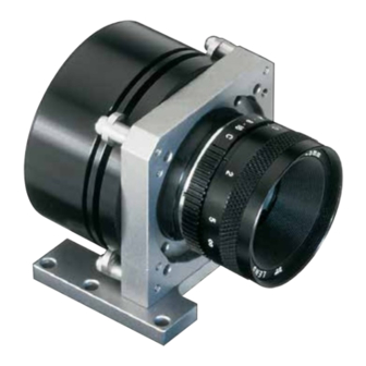
Sample Configuration
1
CCD line scan camera
SK1024U3PD
mounted with
2
Mounting bracket SK5105
3
Clamping claws SK5102
4
Video (CCTV)-objectiv
Read the manual carefully before the initial start-up. For the content table refer to page 2.
The producer reserves the right to change the herein described specifications in case of technical advance of the product.
Kieler Str. 212, 22525 Hamburg, Germany
Tel: +49 40 85 39 97- 0
Fax: +49 40 85 39 97-79
•
•
USB
• Robust cable connections
• Hot-pluggable
• Perfect for movable setups
3
1
2
info@SuKHamburg.de
•
3.0
4
www.SuKHamburg.de
•
Advertisement
Table of Contents

Subscribe to Our Youtube Channel
Related Manuals for Schäfter+Kirchhoff SK1024U3PD


Summary of Contents for Schäfter+Kirchhoff SK1024U3PD
-
Page 1: Instruction Manual
SK1024U3PD • Robust cable connections Monochrome Line Scan Camera • Hot-pluggable • Perfect for movable setups 1024 pixels, 10 µm x 10 µm, 50 / 25 MHz pixel frequency Instruction Manual 05.2014 Sample Configuration CCD line scan camera SK1024U3PD mounted with... -
Page 2: Table Of Contents
Contents Contents ..................................2 Introducing the SK1024U3PD Line Scan Camera with USB 3.0 Interface ............ 3 Intended Purpose and Overview......................3 System Setup at a Glance ........................3 Computer System Requirements ......................4 SK1024U3PD Line Scan Camera - Specifications ................. 4 Installation and Setup ............................ -
Page 3: Introducing The Sk1024U3Pd Line Scan Camera With Usb 3.0 Interface
Introducing the SK1024U3PD Line Scan Camera with USB 3.0 Interface Introducing the SK1024U3PD Line Scan Camera with USB 3.0 Interface Intended Purpose and Overview The SK line scan camera series is designed for both wide integration time, synchronization mode or shading... -
Page 4: Computer System Requirements
High-performance video card, PCIe bus • Operating System Windows 7 (64- or 32-bit), Windows XP (Service Pack 3) • Compact disk drive for software installation. SK1024U3PD Line Scan Camera - Specifications Sensor category CCD Monochrome Sensor Sensor type IL-P1-1024 Pixel number... -
Page 5: Installation And Setup
Installation and Setup Installation and Setup Mechanical Installation: Mounting Options and Dimensions Mounting Options Optics Handling • The best fixing point of the camera is the seat for • If the camera and the optics are ordered as a kit, the mounting bracket SK5105, which is available as the components are pre-assembled and shipped as an accessory. -
Page 6: Electrical Installation: Connections And I/O Signals
Electrical Installation: Connections and I/O Signals • The USB 3.0 interface provides data transfer, camera control and power supply capabilities to the SK1024U3PD line scan camera. If you want to operate the camera in Free Run (SK Mode 0) trigger mode the USB 3.0 cable is the only connection you have to make. -
Page 7: Software Installation
Installation and Setup Software Installation • The PC hardware requirements are listed in section 1.3 Computer System Requirements, p. 4 • See section 2.2 Electrical Installation: Connections and I/O Signals, p. 6. prior to software installation. • This section focusses on driver installation and initial operation of the camera. For a comprehensive description of the software package, see the separate SK91USB3-WIN software manual. -
Page 8: Camera Control And Performing A Scan
Camera Control and Performing a Scan Software: SkLineScan Start the SkLineScan program. • If the SK1024U3PD camera is identified correctly confirm with "OK". The "Signal window" graphicaly showing the intensity signals of the sensor pixels • The most common functions of the line scan camera (oscilloscope display) will open. -
Page 9: Basic Visualization Of The Sensor Output
Camera Control and Performing a Scan Basic Visualization of the Sensor Output Signal Window / Oscilloscope Display The signal window plots the digitalized brightness profile as signal intensity (y-axis) versus the sensor length (x-axis) at a high refresh rate. The scaling of the y-axis depends on the resolution of the A/D converter: The scale range is from 0 to 255 for 8-bits and from 0 to 4095 for 12-bits. -
Page 10: Adjustments For Optimum Scan Results
Camera Control and Performing a Scan Adjustments for Optimum Scan Results Prior to a scan, the following adjustments and parameter settings should be considered for optimum scan signals: • Lens focussing • Integration time • Sensor alignment • Synchronization of the sensor exposure and the object surface velocity, trigger mode •... -
Page 11: Sensor Alignment
Camera Control and Performing a Scan Sensor Alignment If you are operating with a linear illumination source, check the alignment of the illumination source and the sensor prior to a shading correction, as rotating the line sensor results in asymmetric vignetting. Sensor and optics rotated in apposition Sensor and optics aligned Gain/Offset Control Dialog... -
Page 12: Shading Correction
Camera Control and Performing a Scan Shading Correction Shading Correction compensates for non-uniform illumination, lens vignetting as well as any differences in pixel sensitivity. The signal from a white homogeneous background is obtained and used as a reference to correct each pixel of the sensor with an individual factor, scaled up to the intensity maximum (255 at 8-bit resolution and 4095 at 12-bit) to provide a flat signal. -
Page 13: Integration Time
Camera Control and Performing a Scan Shading Correction Memories and API Functions As an alternative to the user dialog, a new shading correction reference signal can also be created by using appli- cation programming interface (API) functions. The relationshhip between the storage locations and the related API functions are shown in the diagram below. -
Page 14: Synchronization Of The Imaging Procedure And The Object Scan Velocity
Camera Control and Performing a Scan Synchronization of the Imaging Procedure and the Object Scan Velocity • A two-dimensional image is generated by moving either the object or the camera. The direction of the translation movement must be orthogonal to the sensor axis of the CCD line scan camera. To obtain a proportional image with the correct aspect ratio, a line synchronous transport with the laterally •... - Page 15 Each single line scan is triggered by the falling edge of a TTL signal supplied to LINE SYNC A input. The SK1024U3PD line scan camera facilitates advanced synchronization control by a second trigger input LINE SYNC B. For a detailed description see Advanced Synchronization Control, p.
-
Page 16: Advanced Sklinescan Software Functions
Advanced SkLineScan Software Functions Advanced SkLineScan Software Functions Camera Control by Commands In addition to user dialog inputs, the SkLineScan software also provides the option to adjust any camera settings, such as gain, offset, trigger modes, by sending control commands directly. Similarly, current parameters, as well as specific product information, can be read from the camera using the request commands. -
Page 17: Set Commands
Request Commands Set Operation Description Request Return Description Goooo<CR> even gain setting (channel A) 0-24 dB K<CR> SK1024U3PD returns SK type number Boooo<CR> odd gain setting (channel B) 0-24 dB R<CR> Rev1.08 returns revision number S<CR> SNr00163 returns serial number Oppp<CR>... -
Page 18: Advanced Synchronization Control
Advanced SkLineScan Software Functions Advanced Synchronization Control The basic synchronization function makes use of the trigger input LINE SYNC A. The trigger mode is determined by the settings in the "Camera Control" dialog, e.g. LineStart (1) or ExposureStart (4). Advanced trigger functions are provided by combining LINE SYNC A with a second trigger input LINE SYNC B. The operation mode is controlled by the entries in the Sync Control Register (SCR). -
Page 19: Example Timing Diagrams Of Advanced Synchronization Control
Advanced SkLineScan Software Functions Example Timing Diagrams of Advanced Synchronization Control Annotations: SyncA = LINE SYNC A (external line synchronization input, I/O connector) SyncB = LINE SYNC B (external line synchronization input, I/O connector) Count = internal counter Trigger = Generated trigger pulses from the Trigger Control stage. The signal goes to the Trigger Divider stage inside the camera. -
Page 20: Sensor Information
Sensor Information Sensor Information Manufacturer: DALSA Corp. Type: IL-P1-1024 Data source: DALSA Line Scan Sensors, Document 03-036-00134-05 Pin Functional Description Block Diagram Page 20... -
Page 21: Typical Performance Data And Sensor Specifications
Sensor Information Typical Performance Data and Sensor Specifications Page 21... -
Page 22: Glossary
Glossary Shading correction Exposure period is the illumination cycle of a line scan sensor. It is the Shading Correction, p. 17 integration time plus the additional time to complete the read-out of the accumulated charges and the output procedure. While the charges from a finished line scan are being read out, the next line scan is being exposed. -
Page 23: Ce-Conformity
CE-Conformity Warranty This manual has been prepared and reviewed as carefully as possible but no warranty is given or implied for any errors of fact or in interpretation that may arise. If an error is suspected then the reader is kindly requested to inform us for appropriate action. -
Page 24: Accessories And Spare Parts
Accessories and Spare Parts Mounting bracket SK5105 Order Code Warp-resistant construction for mounting the line scan camera Clamp set SK5102 Order Code to lock the line scan camera in a desired position (set of 4) Mounting console SK5105-2 Order Code for indirect mounting of the line scan camera via the extension tube, suitable for an extension tube larger than 50 mm, for example with a macro lens.
Need help?
Do you have a question about the SK1024U3PD and is the answer not in the manual?
Questions and answers