
Related Manuals for Strebel Geneva C3


Summary of Contents for Strebel Geneva C3
- Page 1 STREBEL GENEVA ATMOSPHERIC GAS BOILER INSTALLATION, OPERATING AND MAINTENANCE MANUAL...
- Page 2 INDEX TABLE TECHNICAL DATA SECTION 1 GENERAL SECTION 2 LOCATION SECTION 3 VENTILATION SECTION 4 GAS SUPPLY SECTION 5 FLUE SYSTEM SECTION 6 WATER CIRCULATION SYSTEM SECTION 7 ELECTRICAL SUPPLY SECTION 8 INSTALLATION SECTION 9 COMMISSIONING AND TESTING SECTION 10 SERVICING SECTION 11 FAULT FINDING...
-
Page 3: Technical Data
TECHNICAL DATA BOILER MODEL Number Of Sections 21.4 31.7 52.3 62.7 73.7 83.8 Input Btu/hr 73,017 108,160 143,304 178,448 213,932 251,464 285,926 19.3 28.6 37.7 47.1 56.5 66.4 75.6 Output Btu/hr 65,852 97,583 128,632 160,705 192,778 226,557 257,947 Water Content Lits 12.5 17.5... -
Page 4: Installation Instructions
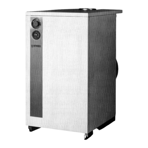
INSTALLATION INSTRUCTIONS GENERAL The STREBEL GENEVA ‘PV’ & ‘C’ range of Gas Fired Boilers are floor mounted open flued units for connection to indirect heating and hot water systems. The Geneva heat exchanger body is constructed of cast iron sections with a stainless steel atmospheric gas burner suitable for Natural Gas and LPG (site conversion) the boilers as standard are fitted with electronic ignition. -
Page 5: Gas Supply
Mechanical Ventilation. The minimum quantity of air required for combustion and boiler house ventilation shall be supplied at a minimum flow rate in accordance with BS. 6644. All air inlet and extract fans shall be fitted with automatic controls causing safety shut-down or lockout of the boiler(s) in the event of the inlet or extract air flow failing. - Page 6 ELECTRICAL SUPPLY The electrical supply should be 220/250V, 50Hz, and fused at 3 amps. A suitable independent switch fuse should be installed for each boiler, adjacent to the boiler. WARNING : This appliance must be earthed. GENEVA ‘C’ & ‘PV’ SCHEMATIC WIRING DIAGRAM With Electronic Ignition.
-
Page 7: Installation
INSTALLATION The boiler is delivered assembled, on a wooden crate with protection for transportation and site positioning. Do not remove protection before final positioning. The boiler jackets and control panel are fitted. The following minimum clearances around the boiler, for installation and servicing purposes, are recommend: Above the top of the boiler (space for cleaning the flueways) 600mm, one side of the boiler should allow access of 500mm. - Page 8 GENEVA ‘PV’ MODEL ‘PV’ DIMENSIONS MM Ø I CIRCULATING PUMP CHARACTERISTIC...
-
Page 9: Commissioning And Testing
COMMISSIONING AND TESTING Before commencing to commissioning the boiler, check the following:- Electrical Electrical supply is switched off. All electrical connections are sound and correctly made. Electrical system is correctly earthed. Gas Supply Gas supply is purged of air, and tested for soundness as described in BS. 6891 : IGE/UP/2 Gas Installation Pipework, Boosters and Compressors on Industrial and Commercial Premises. -
Page 10: Fault Finding
10.0 SERVICING Before servicing the boiler, switch off electricity supply and then turn off main gas cock. 10.1 To Clean Boiler 1. Remove jacket front panel. 2. Disconnect pilot line. Fully Automatic Models: Disconnect leads for ignition and probe electrodes 3. - Page 11 (b) Earth lead to burner not connected. (c) Loose connections on probe lead or earth lead in junction box, control panel or plugs and sockets. (d) Faulty Control box. (e) No earth connection on incoming supply. Note: The probe circuit may be tested with a micro ammeter connected in the probe lead. A reading of al lest 10 micro-amps should be recorded when the burner is alight.
-
Page 12: Control Panel Layout
Fig. 1 GENEVA ‘C’ & ‘PV’ BOILERS CONTROL PANEL LAYOUT LEGEND On / Off Switch Boiler Control Thermostat Boiler Thermometer (Plus Boiler Pressure Gauge On ‘PV’ Versions) Flue Gas Spillage Detector Light (B2) Control Box Lock Out Light And Reset Button (B1) Flue Gas Spillage Detector Reset (E2) Boiler High Limit Thermostat Reset (E1) Fig. - Page 13 Fig. 3 ELEKTROGAS VM-L GAS VALVE Slow Opening and Fast Closing Valve with Hydraulic Damper and Flow - Rate Control Slow opening time : It can be regulated from a fast speed of 4 sec, to a slow speed of 25 sec. (Valves are delivered with a standard opening time of 10 - 12 seconds).
-
Page 14: Lpg Conversion
LPG CONVERSION The boilers are supplied as standard to be run on natural gas. Should it be necessary to convert the boiler to LPG the following operations must be carried out : 1. Remove jacket front panel. 2. Switch off electrical supply. 3. - Page 16 The company reserves the right to change the specification and dimensions without prior notice 6/96 STREBEL Ltd. 1F, Albany Park Industrial Estate Frimley Road, Camberley Surrey GU15 2PL Telephone : (01276) 685422 Fax: : (01276) 685405...
Need help?
Do you have a question about the Geneva C3 and is the answer not in the manual?
Questions and answers