Compaq AlphaServer ES40 Service Manual
Hide thumbs
Also See for AlphaServer ES40:
- Installation manuals (32 pages) ,
- Upgrade installation (32 pages) ,
- Owner's manual (228 pages)
Table of Contents
Troubleshooting

Related Manuals for Compaq AlphaServer ES40


Summary of Contents for Compaq AlphaServer ES40
- Page 1 AlphaServer ES40 Service Guide Order Number: EK–ES240–SV. A01 This guide is intended for service providers and self- maintenance customers responsible for Compaq AlphaServer ES40 systems. Compaq Computer Corporation...
- Page 2 The software may be used or copied only in accordance with the terms of the agreement. COMPAQ and the Compaq logo are registered in United States Patent and Trademark Office. Tru64 is a trademark of Compaq Computer Corporation. AlphaServer and OpenVMS are trademarks of Digital Equipment Corporation.
- Page 3 Attention! Ceci est un produit de Classe A. Dans un environnement domestique, ce produit risque de créer des interférences radioélectriques, il appartiendra alors à l'utilisateur de prendre les mesures spécifiques appropriées. FCC Notice: This equipment generates, uses, and may emit radio frequency energy. The equipment has been type tested and found to comply with the limits for a Class A digital device pursuant to Part 15 of FCC rules, which are designed to provide reasonable protection against such radio frequency interference.
-
Page 5: Table Of Contents
System Access ..................1-30 1.16 Console Terminal ................1-32 Chapter 2 Troubleshooting Questions to Consider ................2-2 Diagnostic Tables .................. 2-3 Service Tools and Utilities ..............2-9 2.3.1 Error Handling/Logging Tools (Compaq Analyze)......2-9 2.3.2 Loopback Tests................2-9 2.3.3 SRM Console Commands..............2-9... - Page 6 2.3.9 StorageWorks Command Console (SWCC)........2-12 Information Resources ................ 2-13 2.4.1 Compaq Service Tools CD............. 2-13 2.4.2 AlphaServer ES40 Service HTML Help File ........ 2-13 2.4.3 Alpha Systems Firmware Updates ..........2-13 2.4.4 Fail-Safe Loader ................2-14 2.4.5 Software Patches ................2-14 2.4.6...
- Page 7 4-52 4.21 sys_exer ....................4-54 4.22 test....................... 4-56 Chapter 5 Error Logs Error Log Analysis with Compaq Analyze..........5-2 5.1.1 WEB Enterprise Service (WEBES) Director ........5-3 5.1.2 Invoking the GUI ................5-4 5.1.3 Problem Found Report..............5-6 Fault Detection and Reporting ............5-12 Machine Checks/Interrupts ..............
- Page 8 6.4.1 Setting the Date and Time............6-21 6.4.2 Setting Up the Hard Disk............. 6-22 6.4.3 Setting the Level of Memory Testing..........6-23 Setting Automatic Booting..............6-24 6.5.1 Windows NT and Auto Start............6-25 6.5.2 Setting Tru64 UNIX or OpenVMS Systems to Auto Start ... 6-26 Changing the Default Boot Device............
- Page 9 Chapter 8 FRU Removal and Replacement FRUs ..................... 8-2 8.1.1 Power Cords ..................8-5 8.1.2 FRU Locations ................8-6 8.1.3 Important Information Before Replacing FRUs ......8-8 Removing Enclosure Panels on a Tower or Pedestal ......8-10 Accessing the System Chassis in a Cabinet........8-14 Removing Covers from the System Chassis........
- Page 10 Cbox Read Register ................D-8 Exception Address Register (EXC_ADDR) ........D-10 Interrupt Enable and Current Processor Mode Register (IER_CM).. D-12 Interrupt Summary Register (ISUM) ..........D-14 PAL Base Register (PAL_BASE) ............D-16 Ibox Control Register (I_CTL)............D-18 D.10 Process Context Register (PCTX)............D-23 D.11 21272-CA Cchip Miscellaneous Register (MISC).......
- Page 11 4–3 clear_error ................... 4-10 4–4 deposit and examine ................4-12 4–5 exer...................... 4-16 4–6 floppy_write..................4-21 4–7 grep ..................... 4-22 4–8 hd ......................4-24 4–9 info 0....................4-26 4–10 info 1....................4-27 4–11 info 2....................4-28 4–12 info 3....................4-29 4–13 info 4....................
- Page 12 Figures 1–1 System Block Diagram................1-2 1–2 Compaq AlphaServer ES40 Systems ............ 1-4 1–3 Components Top/Front View (Pedestal/Rackmount Orientation) ..1-6 1–4 Rear Components (Pedestal/Rackmount Orientation)......1-7 1–5 Rear Connectors..................1-8 1–6 Control Panel ..................1-10 1–7 Component and Connector Locations ..........1-12 1–8...
- Page 13 6–7 AlphaBIOS Utilities Menu..............6-29 6–8 Run Maintenance Program Dialog Box ..........6-30 6–9 CPU Slot Locations (Pedestal/Rack) ........... 6-40 6–10 CPU Slot Locations (Tower)..............6-41 6–11 Stacked and Unstacked DIMMs ............6-43 6–12 Memory Configuration (Pedestal/Rack) ..........6-44 6–13 Memory Configuration (Tower)............
- Page 14 Show Error Message Translation ............4-48 4–3 Bit Assignments for Error Field............4-51 5–1 Compaq AlphaServer ES40 Fault Detection and Correction....5-13 5–2 Machine Checks/Interrupts ..............5-14 5–3 Sample Error Log Event Structure Map (ES40 with 10 PCI Slots)..5-17 6–1...
- Page 15 D–11 21272-CA Device Interrupt Request Register Fields......D-30 D–12 21272-CA Pchip Error Register Fields..........D-33 D–13 21272-CA Array Address Register (AAR) ..........D-35 D–14 DPR Locations A0:A9................ D-37 D–15 Nine Bytes Read from Power Supply ..........D-40 D–16 DPR 680 Fatal Registers..............D-41 D–17 CPU and System Uncorrectable Machine Check Logout Frame ..
-
Page 17: Preface
Preface Intended Audience This manual is for service providers and self-maintenance customers who are responsible for servicing Compaq AlphaServer ES40 systems. WARNING: To prevent injury, access is limited to persons who have appropriate technical training and experience. Such persons are expected to understand the hazards of working within this equipment and take measures to minimize danger to themselves or others. - Page 18 Chapter 4, SRM Console Diagnostics, describes SRM console diagnostic commands. • Chapter 5, Error Logs, describes error analysis with Compaq Analyze. • Chapter 6, System Configuration and Setup, explains how to set up the system, configure devices, and ensure system security.
-
Page 19: Compaq Alphaserver Es40 Documentation
Rackmount Installation Guide EK-ES240-RG Rackmount Installation Template EK-ES4RM-TP Model 1 to Model 2 Upgrade EK-ES4M2-UP ES40 DIMM Information Sheet EK-MS610-DM Information on the Internet You can access service tools and more information about the ES40 from Compaq Web sites. See Chapter 2. -
Page 21: Chapter 1 System Overview
Chapter 1 System Overview This chapter provides an overview of the system in these sections: • System Architecture • System Enclosures • System Chassis—Front View/Top View • System Chassis—Rear View • I/O Ports and Slots • Control Panel • System Motherboard •... -
Page 22: System Architecture
Command, Address, and Control lines for each Memory Array C-chip Control lines for D-chips CAPbus P-chip 64 bit PCI P-chip 64 bit PCI 1 or 2 Memory Arrays Data First Memory CPUs Data 1 or 2 Memory 8 D-chips Arrays B-cache PKW1400A-99 Compaq AlphaServer ES40 Service Guide... - Page 23 This system is designed to fully exploit the potential of the Alpha 21264 chip by using a switch-based (or point-to-point) interconnect system. With a traditional bus design, the processors, memory, and I/O modules share the bus. As the number of bus users increases, the transactions interfere with one another, increasing latency and decreasing aggregate bandwidth.
-
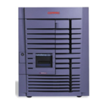
Page 24: System Enclosures
System Enclosures The Compaq AlphaServer ES40 family consists of a standalone tower, a pedestal with expanded storage capacity, and a cabinet. Figure 1–2 Compaq AlphaServer ES40 Systems Rackmount Pedestal Tower PK0212 Compaq AlphaServer ES40 Service Guide... - Page 25 Model Variants AlphaServer ES40 systems are offered in two models. The entry-level model provides connectors for four DIMMs on each of the memory motherboards (MMBs) and connectors for six PCI options on the PCI backplane. To upgrade from Model 1 to Model 2, you replace the PCI backplane and the four memory motherboards.
-
Page 26: System Chassis-Front View/Top View
System Chassis—Front View/Top View Figure 1–3 Components Top/Front View (Pedestal/Rackmount Orientation) PK0201 Operator control panel CD-ROM drive Removable media bays Floppy diskette drive Storage drive bays Fans CPUs Memory PCI cards Compaq AlphaServer ES40 Service Guide... -
Page 27: System Chassis-Rear View
System Chassis—Rear View Figure 1–4 Rear Components (Pedestal/Rackmount Orientation) PK0206 Power supplies PCI bulkhead I/O ports System Overview... -
Page 28: I/O Ports And Slots
I/O Ports and Slots Figure 1–5 Rear Connectors Pedestal/ Rack Tower PK0209 Compaq AlphaServer ES40 Service Guide... - Page 29 Rear Panel Connections Modem port—Dedicated 9-pin port for connection by modem to remote management console. COM2 serial port—Extra port to modem or any serial device. Keyboard port—To PS/2-compatible keyboard. Mouse port—To PS/2-compatible mouse. COM1 MMJ-type serial port/terminal port —For connecting a console terminal.
-
Page 30: Control Panel
(RMC) command line. The RMC is powered separately from the rest of the system and can operate as long as one power supply is plugged in. (See Chapter 7.) 1-10 Compaq AlphaServer ES40 Service Guide... - Page 31 Power LED (green). Lights when the power button is depressed and system power passes initial checks. Reset button. A momentary contact switch that restarts the system and reinitializes the console firmware. Power-up messages are displayed, and then the console prompt is displayed or the operating system boot messages are displayed, depending on how the startup sequence has been defined.
-
Page 32: System Motherboard
PCI backplane interconnect. Figure 1–7 Component and Connector Locations RMC Corner Connector to I/O P-chip P-chip MMB1 CPU3 D-chip D-chip D-chip D-chip CPU2 MMB3 C-chip CPU1 MMB0 D-chip D-chip D-chip D-chip CPU0 MMB2 PK-0323-99 1-12 Compaq AlphaServer ES40 Service Guide... - Page 33 The system motherboard has the majority of the logic for the system, including the CPU, MMB connectors, the PCI connector to I/O, the D-chips and P-chips, the logic for the remote management console (RMC), and the jumpers for the fail-safe loader (FSL). Figure 1–7 shows the location of components and connectors on the system motherboard.
-
Page 34: Cpu Card
CPU Card An AlphaServer ES40 can have up to four CPU cards. In addition to the Alpha 21264 chip, the CPU card has a 4-Mbyte second-level cache and a 2.2V DC-to-DC converter with heatsink that provides the required voltage to the Alpha chip. Power-up diagnostics are stored in a flash SROM on the card. - Page 35 The 21264 microprocessor is a superscalar CPU with out-of-order execution and speculative execution to maximize speed and performance. It contains four integer execution units and dedicated execution units for floating-point add, multiply, and divide. It has an instruction cache and a data cache on the chip. Each cache is a 64 KB, two-way, set associative, virtually addressed cache that has 64-byte blocks.
-
Page 36: Memory Architecture And Options
Address Arrays 0 & 1 Address Arrays 2 & 3 256 Data + 32 Check Bits 256 Data + 32 Check Bits Data Data Bus 0 Bus 1 C-Chip To all eight D-Chips To all eight D-Chips PK0272 1-16 Compaq AlphaServer ES40 Service Guide... - Page 37 Memory Architecture Memory throughput in this system is maximized by the following features: • Two independent, wide memory data buses • Very low memory latency (120 ns) and high bandwidth with 12 ns clock • ECC memory Each data bus is 256 bits wide (32 bytes). The memory bus speed is 83 MHz. This yields 2.6 GB/sec bandwidth per bus (32 x 83 MHz = 2.6 GB/sec).
-
Page 38: Pci Backplane
COM2 CD-ROM Modem Printer Flash ROM Floppy (NVRAM functions) C-chip (4) or (3) Interrupts PCI Slot Config (6) or (3) PCI Slot P-chip 1 PCI 1 PK-0319A-98 NOTE: No USB options are currently supported. 1-18 Compaq AlphaServer ES40 Service Guide... - Page 39 PCI Bus Implementation • Is fully compliant with the PCI Version 2.1 Specification • Operates at 33 MHz, delivering a peak bandwidth of 500 MB/sec; over 250 Mbytes/sec for each PCI bus • Has six option slots (Model 1) or ten option slots (Model 2) •...
-
Page 40: Remote System Management Logic
ADDR COM1(Modem Port) Latch DUART System COM1 UART AUX5 AUX5 ADDRESS AUX5 Dual- Port DATA DATA Isolator SRAM AUX5 AUX5 PWR5 Flash AUX5 STATUS CONTROL STATUS ADDRESS Register Array CONTROL DATA AUX5 AUX5 PKO912 1-20 Compaq AlphaServer ES40 Service Guide... - Page 41 The error log information is written to the DPR by Compaq Analyze (see Chapter 5) and then written back to the EEPROMs by the RMC. This ensures that the error log is available on a FRU after power has been lost.
-
Page 42: System Power Controller (Spc)
Remote management console logic ( remote power up/down, reset) It provides outputs to: • Power supplies and DC/DC regulators (power supply enables) • Processors (DC_OK, reset) • TIG bus chip (handshake) • Remote management console (power status) 1-22 Compaq AlphaServer ES40 Service Guide... -
Page 43: Remote Management Console (Rmc)
1.10.2 Remote Management Console (RMC) The remote management console (RMC) provides a mechanism for remotely monitoring a system and manipulating it on a very low level. It also provides access to the repository for all error information in the system. This provides the operator, either remotely or locally, with the ability to monitor the system (voltages, temperature, fans, error status) and manipulate it (reset, power on/off, halt) without any interaction on the part of the operating system. -
Page 44: Power Supplies
The power supplies provide power to components in the system box. The number of power supplies required depends on the system configuration. Figure 1–12 Power Supplies Tower Pedestal/Rack 1 1 1 2 2 2 PK0207 1-24 Compaq AlphaServer ES40 Service Guide... - Page 45 One to three power supplies provide power to components in the system box. The system supports redundant power configurations to ensure continued system operation if a power supply fails. See Chapter 6 for power supply configurations. When more than one power supply is installed, the supplies share the load. The power supplies select line voltage automatically (120V or 240V and 50 Hz or 60 Hz).
-
Page 46: Fans
1.12 Fans The system has six hot-plug fans that provide front-to-back airflow. Figure 1–13 System Fans PK0208a 1-26 Compaq AlphaServer ES40 Service Guide... -
Page 47: Fan Descriptions
The system fans are shown in Figure 1–13 and described in Table 1–1. Table 1–1 Fan Descriptions Area Cooled Fan Failure Scenario Number PCI card cage Both fans are powered at all times. If one Removable media fan fails, all other system fans speed up to 4.5-in. -
Page 48: Removable Media Storage
5.25-inch half- height drives or one additional full-height drive. The 5.25-inch half height area has a divider that can be removed to mount one full-height 5.25-inch device. Figure 1–14 Removable Media Drive Area PK0233 1-28 Compaq AlphaServer ES40 Service Guide... -
Page 49: Hard Disk Drive Storage
1.14 Hard Disk Drive Storage The system chassis can have either one or two storage disk cages. You can install four 1.6-inch hard drives in each storage disk cage. See Chapter 8 for information on replacing hard disk drives. Figure 1–15 Hard Disk Storage Cage with Drives (Tower View) PK0935 System Overview 1-29... -
Page 50: System Access
At the time of delivery, the system keys are taped inside the small front door that provides access to the operator control panel and removable media devices. Figure 1–16 System Lock and Key Tower Pedestal PK0224 1-30 Compaq AlphaServer ES40 Service Guide... - Page 51 Both the tower and pedestal systems have a small front door through which the control panel and removable media devices are accessible. At the time of deliv- ery, the system keys are taped inside this door. The tower front door has a lock that lets you secure access to the disk drives and to the rest of the system.
-
Page 52: Console Terminal
COM1 or COM2 port or a VGA monitor connected to a VGA adapter on PCI 0. A VGA monitor requires a keyboard and mouse. Figure 1–17 Console Terminal Connections (Local) Tower Pedestal/Rack PK0225 1-32 Compaq AlphaServer ES40 Service Guide... -
Page 53: Chapter 2 Troubleshooting
Chapter 2 Troubleshooting This chapter describes the starting points for diagnosing problems on Compaq AlphaServer ES40 systems. The chapter also provides information resources. • Questions to Consider • Diagnostic Tables • Service Tools and Utilities • Information Resources Troubleshooting... -
Page 54: Questions To Consider
See Chapter 7. ½ If the operating system has crashed and rebooted, the CCAT (Compaq Crash Analysis Tool), the Compaq Analyze service tools (to interpret error logs), the SRM crash command, operating system exercisers, and DEC VET can be used to diagnose system problems. -
Page 55: Diagnostic Tables
Diagnostic Tables System problems can be classified into the following five categories. Using these categories, you can quickly determine a starting point for diagnosis and eliminate the unlikely sources of the problem. 1. Power problems—Table 2–1 2. No access to console mode—Table 2–2 3. -
Page 56: Power Problems
If AC power is present, use the RMC Chapter 7 env command to check environmental status. Appendix B Check jumper J26. If the system must be kept running, this jumper can be positioned to override an overtempera- ture condition. Compaq AlphaServer ES40 Service Guide... -
Page 57: Problems Getting To Console Mode
Table 2–2 Problems Getting to Console Mode Symptom Action Reference Power-up screen is not Note any error beep codes and Chapter 3 displayed at system observe the OCP display for a console. failure detected during self-tests. Check keyboard and monitor Chapter 1 connections. -
Page 58: Problems Reported By The Console
Storage devices are Check cables and seating of missing from the show drives. Check power to an config display. external storage box. • PCI devices are missing Checking seating of modules. from the show config display. Compaq AlphaServer ES40 Service Guide... -
Page 59: Boot Problems
Table 2–4 Boot Problems Symptom Action Reference System cannot find Check the system configuration for the Chapter 6 boot device. correct device parameters (node ID, device name, and so on). • For UNIX and OpenVMS, use the show config and show device commands. -
Page 60: Errors Reported By The Operating System
If the problem is intermittent, ensure Chapter 5 that Compaq Analyze has been installed and is running in background mode (GUI does not have to be running) to determine the defective FRU. Compaq AlphaServer ES40 Service Guide... -
Page 61: Service Tools And Utilities
The Tru64 UNIX, OpenVMS, and Microsoft Windows NT operating systems provide fault management error detection, handling, notification, and logging. The primary tool for error handling is Compaq Analyze, a fault analysis utility designed to analyze both single and multiple error/fault events. Compaq Analyze uses error/fault data sources other than the traditional binary error log. -
Page 62: Alphabios Menus
AC wall outlet and a console terminal is attached to the system. This feature ensures that you can gather information when the operating system is down and the SRM console is not accessible. See Chapter 7. 2-10 Compaq AlphaServer ES40 Service Guide... -
Page 63: Operating System Exercisers (Dec Vet)
This file can be used to determine why the system crashed. CCAT, the Compaq Crash Analysis Tool, is the primary crash dump analysis tool for analyzing crash dumps on Alpha systems running Tru64 UNIX or OpenVMS. -
Page 64: Storageworks Command Console (Swcc)
TCP/IP network connection, a SCSI connection, or a serial connection. You can download the Command Console from the following Web site: http://www.storage.digital.com/homepage/support/swcc/ 2-12 Compaq AlphaServer ES40 Service Guide... -
Page 65: Information Resources
Compaq Service Tools CD The Compaq Service Tools CD-ROM enables field engineers to upgrade customer systems with the latest version of software when the customer does not have access to Compaq Web pages. The CD-ROM Web site is: http://caspian1.zko.dec.com/service_tools/ 2.4.2... -
Page 66: Fail-Safe Loader
Internet (using the firmware update URL above) to create your own fail-safe loader diskette. See Chapter 3 for information on forcing a fail-safe floppy load. 2.4.5 Software Patches Software patches for the supported operating systems are available from the World Wide Web as follows: http://www.digital.com/alphaserver/support.html 2-14 Compaq AlphaServer ES40 Service Guide... -
Page 67: Late-Breaking Technical Information
2.4.6 Late-Breaking Technical Information You can download up-to-date files and late-breaking technical information from the Internet. The information includes firmware updates, the latest configuration utilities, software patches, lists of supported options, and more. http://www.digital.com/alphaserver/es40/es40.html 2.4.7 Supported Options A list of options supported on the system is available on the Internet: http://www.digital.com/alphaserver/es40/es40_sol.pdf Troubleshooting 2-15... -
Page 69: Chapter 3 Power-Up Diagnostics And Display
Chapter 3 Power-Up Diagnostics and Display This chapter describes the power-up process and RMC, SROM, and SRM power- up diagnostics. The following topics are covered: • Overview of Power-Up Diagnostics • System Power-Up Sequence • Power-Up Displays • Power-Up Error Messages •... -
Page 70: Overview Of Power-Up Diagnostics
3. Console firmware diagnostics—These tests are executed by the SRM console code. They test the core system, including boot path devices. Failures during these tests are reported to the console terminal through the power- up screen or console event log. Compaq AlphaServer ES40 Service Guide... -
Page 71: System Power-Up Sequence
System Power-Up Sequence The power-up sequence is described below and illustrated in Figure 3–1. 1. When the power cord is plugged into the wall outlet, 5V auxiliary AC voltage is enabled. The 5 V AUX LEDs on the power supplies are lit, and the system power controller and RMC are initialized. -
Page 72: Power-Up Sequence
Set all CPU_DCOK = True Set SYS_DC_OK = True Set SYS_RESET = False Set CPU(n)_RESET = False Set CPU(n)_RESET = False Disable CPU CPU = All CPUs reload "Alive"? initial Y divisor Continue SROM power-up PK0943 Compaq AlphaServer ES40 Service Guide... - Page 73 Figure 3–1 Power-Up Sequence (Continued) SROM Power-Up Init EV6 Test PCI Determine Config Good Reload Using Flash SROM Init EV6 Test PCI Release CPUs B-Cache Tests Memory Config and Tests Load SRM PK0964 Power-Up Diagnostics and Display...
-
Page 74: Power-Up Displays
SROM and SRM power-up messages, is displayed on the VT terminal screen. If console is set to graphics, no SROM messages are displayed, and the SRM messages are delayed until VGA initialization has been completed. Compaq AlphaServer ES40 Service Guide... - Page 75 • Section 3.3.1 describes the SROM power-up sequence and shows the SROM power-up messages and corresponding OCP messages. • Section 3.3.2 shows the messages that are displayed once the SROM has transferred control to the SRM console. Power-Up Diagnostics and Display...
-
Page 76: Srom Power-Up Display
Cfg Mem Memory data test in progress Memory address test in progress Memory pattern test in progress Memory thrashing test in progress Memory initialization Loading console Load ROM Code execution complete (transfer control) Jump to Console Compaq AlphaServer ES40 Service Guide... - Page 77 SROM Power-Up Sequence When the system powers up, the SROM code is loaded into the I-cache (instruction cache) on the first available CPU, which becomes the primary CPU. The order of precedence is CPU0, CPU1, and so on. The primary CPU attempts to access the PCI bus.
-
Page 78: Srm Console Power-Up Display
PCI-to-ISA bridge, bus 1 bus 0, slot 2 -- vga -- DEC PowerStorm bus 0, slot 15 -- dqa -- Acer Labs M1543C IDE bus 0, slot 15 -- dqb -- Acer Labs M1543C IDE starting drivers 3-10 Compaq AlphaServer ES40 Service Guide... - Page 79 SRM Power-Up Sequence The primary CPU prints a message indicating that it is running the console. Starting with this message, the power-up display is sent to any console terminal, regardless of the state of the console environment variable. If console is set to graphics, the display from this point on is saved in a memory buffer and displayed on the VGA monitor after the PCI buses are sized and the VGA device is initialized.
- Page 80 0000000000000000 2048 MB of System Memory Testing the System Testing the Disks (read only) Testing the Network initializing GCT/FRU at offset 192000 AlphaServer ES40 Console V5.4-5528, built on Feb 1 1999 at 01:43:35 P00>>> 3-12 Compaq AlphaServer ES40 Service Guide...
- Page 81 SRM Power-Up Sequence (Continued) The console is started on the secondary CPUs. The example shows a four- processor system. Various diagnostics are performed. Systems running UNIX or OpenVMS display the SRM console banner and the prompt, Pnn>>>. The number n indicates the primary processor. In a multiprocessor system, the prompt could be P00>>>, P01>>>, P02>>>, or P03>>>.
-
Page 82: Resizing Srm Console Heap
If the configuration is subsequently changed, enter the following command to reset the heap space to its default before you boot the system: P00>>> set heap_expand none Resizing may or may not occur again, depending on whether the console requires additional heap space. 3-14 Compaq AlphaServer ES40 Service Guide... - Page 83 Example 3–3 Memory Resize Crash/Reboot Cycle initialized idle PCB initializing semaphores initializing heap initial heap 200c0 memory low limit = 15e000 heap = 200c0, 17fc0 initializing driver structures initializing idle process PID initializing file system initializing hardware initializing timer data structures lowering IPL CPU 0 speed is 500 MHz create dead_eater...
- Page 84 128 ???? 00000028 992 rx_eif0 00000027 160 ???? 0000002B 1024 rx_eig0 0000002E 992 rx_eih0 0000002D 160 ???? 0000002A 128 ???? 00000030 128 ???? 00000038 2080 ???? 0000003D 22848 sh_cmdsub 00000040 5696 show 00000041 800 setmode 3-16 Compaq AlphaServer ES40 Service Guide...
- Page 85 SYSFAULT CPU0 - pc = 0014faac exception context saved starting at 001FD7B0 GPRs: 0: 00000000 00048FF8 16: 00000000 0000001E 1: 00000000 00150C80 17: 00000000 EFEFEFC8 2: 00000000 001202D0 18: 00000000 001FD2F8 3: 00000000 000011F0 19: 00000000 00000025 4: 00000000 0010C7B8 20: 00000801 FC000000 5: 00000000 00000020 21: 00000000 0008A8B0...
- Page 86 Testing the System Testing the Disks (read only) Testing the Network Partition 0, Memory base: 000000000, size: 080000000 initializing GCT/FRU at offset 1dc000 AlphaServer ES40 Console V5.5-3059, built on May 14 1999 at 01:57:42 P00>>>show heap_expand heap_expand 64KB P00>>> 3-18...
-
Page 87: Srm Console Event Log
3.3.4 SRM Console Event Log The SRM console event log helps you troubleshoot problems that do not prevent the system from coming up to the SRM console. The console event log consists of status messages received during power-up self- tests. Example 3–4 Sample Console Event Log >>>... -
Page 88: Alphabios Startup Screens
256 MB Alpha Processor(s) Status: Processor 0 Running Processors 1, 2, 3 Ready SCSI Controller Initialization... Initialize ATAPI #0... Device: CD-ROM SCSI ID:0 TOSHIBA CD-ROM XM62028 1110 F2=Setup PAUSE=Pause Display ESC=Bypass Network Init PKO950 3-20 Compaq AlphaServer ES40 Service Guide... - Page 89 Example 3–6 AlphaBIOS Boot Screen AlphaBIOS 5.68 Please select the operating system to start: Windows NT Server 4.00 to move the highlight to your choice. Press Enter to choose. AlphaServer Press <F2> to enter SETUP PK0949 Power-Up Diagnostics and Display 3-21...
-
Page 90: Power-Up Error Messages
Backup cache (B-cache) error. Indicates a bad CPU. CPU error BC bad 1-3-3 No mem No usable memory detected. Some memory DIMMs may not be properly seated or some DIMM sets may be faulty. See Section 3.4.3. 3-22 Compaq AlphaServer ES40 Service Guide... - Page 91 A few SROM error messages that appear on the operator control panel are announced by audible error beep codes, an indicated in Table 3–1. For example, a 1-1-4 beep code consists of one beep, a pause (indicated by the hyphen), one beep, a pause, and a burst of four beeps.
-
Page 92: Checksum Error
OpenVMS PALcode V1.3-3, Digital UNIX PALcode V1.4-2 starting console on CPU 0 starting drivers entering idle loop P00>>> Boot update_cd OpenVMS PALcode V1.3-3, Digital UNIX PALcode V1.4-2 starting console on CPU 0 starting drivers entering idle loop 3-24 Compaq AlphaServer ES40 Service Guide... - Page 93 ***** Loadable Firmware Update Utility ***** ------------------------------------------------------------- Function Description ------------------------------------------------------------ Display Displays the system’s configuration table. Exit Done exit LFU (reset). List Lists the device, revision, firmware name, and update revision. Readme Lists important release information. Update Replaces current firmware with loadable data image.
-
Page 94: No Mem Error
Failed M:1 D:2 Failed M:1 D:1 Failed M:0 D:2 Failed M:0 D:1 Incmpat M:1 D:4 Incmpat M:1 D:3 Incmpat M:0 D:4 Incmpat M:0 D:3 Missing M:3 D:2 Illegal M:2 D:2 No usable memory detected 3-26 Compaq AlphaServer ES40 Service Guide... - Page 95 Indicates failed DIMMs. M identifies the MMB; D identifies the DIMM. In this line, DIMM 2 on MMB1 failed. Indicates that some DIMMs in this array are mismatched. All DIMMs in the affected array are marked as incompatible (incmpat). Indicates that a DIMM in this array is missing. All missing DIMMs in the affected array are marked as missing.
-
Page 96: Rmc Error Messages
Bad CPU ROM data Invalid data in EEROM on the CPU. NOTE: The“ CPUn failed” message does not necessarily prevent the completion of power-up. If the system finds a good CPU, it continues the power-up process. 3-28 Compaq AlphaServer ES40 Service Guide... -
Page 97: Rmc Warning Messages
Table 3–3 RMC Warning Messages Message Meaning PSn failed Power supply failed. “n” is 0, 1, or 2. OverTemp Warning System temperature is near the high threshold. Fann failed Fan failed. “n” is 0 through 6. PCI door opened Cover to PCI card cage is off. Reinstall cover. Fan door opened Cover to main fan area (fans 5 and 6) is off. -
Page 98: Srom Error Messages
No real-time clock (TOY) TOY Err Memory data path error Mem Err Memory address line error Mem Err Memory pattern error Mem Err Memory pattern ECC error Mem Err Configuration error on CPU #3 CfgERR 3 3-30 Compaq AlphaServer ES40 Service Guide... - Page 99 Table 3–4 SROM Error Messages (Continued) Code SROM Message OCP Message Configuration error on CPU #2 CfgERR 2 Configuration error on CPU #1 CfgERR 1 Configuration error on CPU #0 CfgERR 0 Bcache failed on CPU #3 error BC Bad 3 Bcache failed on CPU #2 error BC Bad 2 Bcache failed on CPU #1 error...
-
Page 100: Forcing A Fail-Safe Floppy Load
SRM firmware. Figure 3–2 Function Jumpers 1 2 3 1 2 3 1 2 3 1 2 3 E296 1 2 3 4 5 6 7 8 9 10 SC0033 3-32 Compaq AlphaServer ES40 Service Guide... - Page 101 1. Turn off the system. Unplug the power cord from each power supply and wait for the 5V AUX indicators to extinguish. 2. Remove enclosure covers (tower and pedestal) or the front bezel (rackmount) to access the system chassis. See Chapter 8 for illustrations. 3.
-
Page 102: Updating The Rmc
If the RMC is not working, the control panel displays the following message: Bad RMC flash The SRM console also sends a message to the terminal screen: *** Error - RMC detected power up error - RMC Flash corrupted *** 3-34 Compaq AlphaServer ES40 Service Guide... - Page 103 You can update the remote management console firmware from flash ROM using the LFU. 1. Load the update medium. 2. At the UPD> prompt, exit from the update utility, and answer y to the manual update prompt. Enter update RMC to update the firmware. UPD>...
-
Page 105: Chapter 4 Srm Console Diagnostics
Errors are reported to the console terminal, the console event log, or both. If you are not familiar with the SRM console, see the Compaq AlphaServer ES40 User Interface Guide. NOTE: If you are running a Windows NT system, you need to switch from AlphaBIOS to SRM to run SRM console firmware diagnostics. -
Page 106: Diagnostic Command Summary
Searches for “regular expressions”—specific strings of grep characters—and prints any lines containing occurrences of the strings. Dumps the contents of a file (byte stream) in hexadecimal and ASCII. Displays registers and data structures. info Compaq AlphaServer ES40 Service Guide... - Page 107 Table 4–1 Summary of Diagnostic and Related Commands (Continued) Command Function kill Terminates a specified process. Terminates all executing diagnostics. kill_diags more el Same as cat el, but displays the console event log one screen at a time. Runs a requested number of memory tests in the memexer background.
-
Page 108: Buildfru
Field Service. Example 4–1 buildfru P00>>> buildfru smb0.mmb0.dim1 54-24941-EA NI90200100 P00>>> buildfru smb0.cpu0 30-30158-05.AX05 NI94060554 Compaq P00>>> buildfru -s smb0.mmb0.dim1 80 45 P00>>> buildfru -s smb0.mmb0.dim1 80 47 46 45 44 43 42 41 Building of the FRU descriptor on a DIMM, passing a part number and a... - Page 109 NOTE: Be sure to enter the FRU information carefully. If you enter incorrect information, the callout used by Compaq Analyze will not be accurate. Three areas of the EEPROM can be initialized: the FRU generic data, the FRU specific data, and the system specific data. Each area has its own checksum, which is recalculated any time that segment of the EEPROM is written.
- Page 110 P00>>> P00>>> buildf fan4 54-12345-01.a001 ay84412345 Device FAN4 does not support setting FRU values P00>>> Syntax buildfru ( <fru_name> <part_num> <serial_num> [<misc> [<other>]] -s <fru_name> <offset> <byte> [<byte>...] ) Compaq AlphaServer ES40 Service Guide...
- Page 111 (extra characters are truncated). This field is optional, unless <alias> is specified. <other> The FRU’s Compaq alias number, if one exists. This ASCII string may be up to 16 characters (extras are truncated). This field is optional. The beginning byte offset (0–255 hex) within this FRU's <offset>...
-
Page 112: Cat El And More El
DIMx status TIG Bus status DPR status CPU speed status = 0 CPU speed Powerup time = 00-00-00 00:00:00 CPU SROM sync *** Error - Fan 1 failed *** *** Error - Fan 2 failed *** Compaq AlphaServer ES40 Service Guide... - Page 113 CPU 1 failed. Fan 1 and Fan 2 failed. Status and error messages are logged to the console event log at power-up, during normal system operation, and while running system tests. Standard error messages are indicated by asterisks (***). When cat el is used, the contents of the console event log scroll by. Use the Ctrl/S key combination to stop the screen from scrolling, and use Ctrl/Q to resume scrolling.
-
Page 114: Clear_Error
FRU, you must use clear_error all to clear errors. Clears all errors logged to all system FRUs. clear_error all See the show error command for information on the types of errors that might be logged to the FRU EEPROMs. 4-10 Compaq AlphaServer ES40 Service Guide... -
Page 115: Crash
crash The SRM crash command forces a crash dump to the selected device for UNIX and OpenVMS systems. P00>>> crash CPU 0 restarting DUMP: 19837638 blocks available for dumping. DUMP: 118178 wanted for a partial compressed dump. DUMP: Allowing 2060017 of the 2064113 available on 0x800001 device string for dump = SCSI 1 1 0 0 0 0 0. -
Page 116: Deposit And Examine
P00>>> d + ff P00>>> d scbb 820000 examine P00>>> e dpr:34f0 -l -n 5 dpr: 34F0 00000000 dpr: 34F4 00000000 dpr: 34F8 00000000 dpr: 34FC 00000000 dpr: 3500 204D5253 dpr: 3504 352E3558 P00>>> 4-12 Compaq AlphaServer ES40 Service Guide... - Page 117 Deposit The deposit command stores data in the location specified. If no options are given, the system uses the options from the preceding deposit command. If the specified value is too large to fit in the data size listed, the console ignores the command and issues an error.
- Page 118 PCI memory space The PALtemp register set; name is PT0 to PT23. pmem Physical memory (default). Virtual memory. vmem offset Offset within a device to which data is deposited. data Data to be deposited. 4-14 Compaq AlphaServer ES40 Service Guide...
- Page 119 Symbolic forms can be used for the address. They are: The program counter. The address space is set to GPR. The location immediately following the last location referenced in a deposit or examine command. For physical and virtual memory, the referenced location is the last location plus the size of the reference (1 for byte, 2 for word, 4 for longword).
-
Page 120: Exer
P00>>> exer -sb 1 -eb 3 -bc 4 -a ’w’ -d1 ’0x5a’ dka0 Write hex 5a’s to every byte of blocks 1, 2, and 3. The packet size is bc * bs, 4 * 512, 2048 for all writes. 4-16 Compaq AlphaServer ES40 Service Guide... - Page 121 P00>>> ls -l dk*.* r--- dka0.0.0.0.0 P00>>> exer dk*.* -bc 10 -sec 20 -m -a ’r’ dka0.0.0.0.0 exer completed packet elapsed idle 8192 3325 27238400 1360288 P00>>> exer -eb 64 -bc 4 -a ’?w-Rc’ dka0 A destructive write test over block numbers 0 through 100 on disk dka0. The packet size is 2048 bytes.
- Page 122 -eb. If only reading, then specifying neither -l nor -eb defaults to read till eof. If writing, and neither -l nor -eb are specified then exer will write for the size of device. The default is 1. 4-18 Compaq AlphaServer ES40 Service Guide...
- Page 123 Specifies the block size (hex) in bytes. The default is 200 -bs <block_size> (hex). -bc <block_per_io> Specifies the number of blocks (hex) per I/O. On devices without length (tape), use the specified packet size or default to 2048. The maximum block size allowed with variable length block reads is 2048 bytes.
- Page 124 This is not applicable on writes or compares. The default is verbose mode off. -delay <millisecs> Specifies the number of milliseconds to delay when s appears as a character in the action string. 4-20 Compaq AlphaServer ES40 Service Guide...
-
Page 125: Floppy_Write
floppy_write The floppy_write script runs a write test on the floppy drive to determine whether or not you can write on the diskette. Use this script if a customer is unable to write data to the floppy. This is a destructive test, so use a blank floppy. -
Page 126: Grep
Optional matching; indicates that the pattern can match zero or one times. ’[a- z][0-9]?’ matches lowercase letter alone or followed by a single digit. Quote character; prevent the character that follows from having special meaning. 4-22 Compaq AlphaServer ES40 Service Guide... - Page 127 Syntax grep ( [-{c|i|n|v}] [-f <file>] [<expression>] [<file>...] ) Arguments <expression> Specifies the target regular expression. If any regular expression metacharacters are present, the expression should be enclosed with quotes to avoid interpretation by the shell. <file>... Specifies the files to be searched. If none are present, then standard input is searched.
- Page 128 FF FF FF FF FF FF FF FF FF FF FF FF FF FF FF FF ....000001f0 FF FF FF FF FF FF FF FF FF FF FF FF FF FF FF FF ....P00>>> 4-24 Compaq AlphaServer ES40 Service Guide...
- Page 129 Example 4–8 shows a hex dump to DPR location 2b00, ending at block 0. Syntax hd [-{byte|word|long|quad}] [-{sb|eb} <n>] <file>[:<offset>]. Arguments <file>[:<offset>] Specifies the file (byte stream) to be displayed. Options Print out data in byte sizes -byte Print out data by word -word -long Print out data by longword...
-
Page 130: Info
Third Edition (EY-W938E-DP), available from Digital Press, an imprint of Butterworth-Heinemann. • For info 2, see the Galaxy Console and Alpha Systems V5.0 FRU Configuration Tree Specification. • For info 3, see the Tsunami 21272 Chipset Functional Specification. 4-26 Compaq AlphaServer ES40 Service Guide... -
Page 131: Info 1
info 0 Displays the SRM memory descriptors as described in the Alpha System Reference Manual. info 1 Displays the page table entries (PTE) used by the console and operating system to map virtual to physical memory. Valid data is displayed only after a boot operation. -
Page 132: Info 2
ID ff0000ff00ff0002 subtyp 1 HdExt 120 FRU 2800 cnt 1 Type 9 ID ff0000ff00ff0003 subtyp 1 HdExt 120 FRU 28c0 cnt 1 dump each node ? (Y/<N>) dump binary ? (Y/<N>) N P00>>> P00>>> 4-28 Compaq AlphaServer ES40 Service Guide... -
Page 133: Info 3
Example 4–12 shows an abbreviated info 3 display. Example 4–12 info 3 P00>>> info 3 CCHIP CSRs: 801a0000000 002140809A19796F : 0000 00000F6414000125 : 0040 AAR0 0000000040006105 : 0100 AAR1 0000000000007105 : 0140 AAR2 0000000060005005 : 0180 AAR3 0000000070005005 : 01c0 DCHIP CSRs: 801b0000000... -
Page 134: Info 4
00000000 00000000 00000000 00000000 : 0214 cns$fpcr 00000000 00000000 00000000 00000000 : 0318 cns$fpcr+4 8ff00000 8ff00000 8ff00000 8ff00000 : 031c cns$va fffffffc 0016270c 0016270c 16333d20 : 0320 cns$va+4 ffffffff 00000000 00000000 00000000 : 0324 4-30 Compaq AlphaServer ES40 Service Guide... -
Page 135: Kill And Kill_Diags
4.12 kill and kill_diags The kill and kill_diags commands terminate diagnostics that are currently executing. Example 4–14 kill and kill_diags P00>>> memexer 3 P00>>> show_status Program Device Pass Hard/Soft Bytes Written Bytes Read -------- ------------ ------------ ------ --------- ------------- ----------- 00000001 idle system 0000125e... -
Page 136: Memexer
*** Hard Error - Error #41 - Memory compare error Diagnostic Name Device Pass Test Hard/Soft 11-FEB-1999 memtest 00000193 brd0 12:00:01 Expected value: 25c07 Received value 35c07 Failing addr: a11848 *** ERROR - DIMM 1 on MMB 1 Failed *** P00>>> kill_diags P00>>> 4-32 Compaq AlphaServer ES40 Service Guide... - Page 137 If the memory configuration is very large, the console might not test all of the memory. The upper limit is 1 GB. Use the show_status command to display the progress of the tests. Use the kill or kill_diags command to terminate the test. Syntax memexer [number] Arguments...
-
Page 138: Memtest
*** Hard Error - Error #43 - Memory compare error Diagnostic Name Device Pass Test Hard/Soft 1-JAN-2066 memtest 00000118 brd0 12:00:01 Expected value: fffffffe Received value: ffffffff Failing addr: 400004 *** Error - DIMM 3 on MMB 2 Failed *** 4-34 Compaq AlphaServer ES40 Service Guide... - Page 139 Use the show memory command or an info 0 command to see where memory is located. Starting address Length of the section to test in bytes Passcount. In this example, the test will run for 10 passes. The test detected a failure on DIMM 3, which is located on MMB 2. Use the show_status command to display the progress of the test.
- Page 140 You can specify the -f (fast) option so that the explicit data verify sections of the second and third loops are not performed. This does not catch address shorts but stresses memory with a higher throughput. The ECC/EDC logic can be used to detect failures. 4-36 Compaq AlphaServer ES40 Service Guide...
- Page 141 Syntax memtest ( [-sa <start_address>] [-ea <end_address>] [-l <length>] [-bs <block_size>] [-i <address_inc>] [-p <pass_count>] [-d <data_pattern>] [-rs <random_seed>] [-ba <block_address>] [-t <test_mask>] [-se <soft_error_threshold>] [-g <group_name>] [-rb] [-f] [-m] [-z] [-h] [-mb] ) Options Start address. Default is first free space in memzone. End address.
- Page 142 Memory barrier flag. Used only in the -f graycode test. When set an mb is done after every memory access. This guarantees serial access to memory. Used only for block test (4). Uses the data stored at this address to write to each block. 4-38 Compaq AlphaServer ES40 Service Guide...
-
Page 143: Net
4.15 net The net command performs maintenance operations on a specified Ethernet port. Net -ic initializes the MOP counters for the specified Ethernet port, and net -s displays the current status of the port, including the contents of the MOP counters. Example 4–17 net -ic and net -s P00>>>... - Page 144 Syntax net [-ic] net [-s] Arguments Specifies the Ethernet port on which to operate, either ei*0 or <port_name> ew*0. 4-40 Compaq AlphaServer ES40 Service Guide...
-
Page 145: Nettest
4.16 nettest The nettest command tests the network ports using MOP loopback. Typically nettest is run from the built-in console script. Advanced users may want to use the specific options and environment variables described here. Example 4–18 nettest P00>>> nettest ei* P00>>>... - Page 146 You can change other network driver characteristics by modifying the port mode. See the -mode option. Use the show_status display to determine the process ID when terminating an individual diagnostic test. Use the kill or kill_diags command to terminate tests. 4-42 Compaq AlphaServer ES40 Service Guide...
- Page 147 Syntax nettest ( [-f <file>] [-mode <port_mode>] [-p <pass_count>] [-sv <mop_version>] [-to <loop_time>] [-w <wait_time>] [<port>] ) Arguments Specifies the Ethernet port on which to run the test. <port> Options Specifies the file containing the list of network station -f <file> addresses to loop messages to.
- Page 148 2 : all fives 3 : all 0xAs 4 : incrementing data 5 : decrementing data ffffffff : all patterns Specifies the size (hex) of the loop message. The loop_size default packet size is 0x2E. 4-44 Compaq AlphaServer ES40 Service Guide...
-
Page 149: Set Sys_Serial_Num
4.17 set sys_serial_num The set sys_serial_num command sets the system serial number. This command is used by Manufacturing for establishing the system serial number, which is then propagated to all FRU devices that have EEPROMs. The sys_serial_num environment variable can be read by the operating system. -
Page 150: Show Error
FF 00 00 00 00 00 00 00 00 00 00 00 00 00 00 00 ....001f8438 00 00 00 00 00 00 00 00 00 00 00 00 00 4A 21 0D .....J!. SMB0 SYS_SERIAL_NUM Mismatch P00>>> 4-46 Compaq AlphaServer ES40 Service Guide... - Page 151 An SDD error has been logged. SDDs (symptom-directed diagnostics) are generic diagnostic exercisers that try to cause random behavior and look for failures or “symptoms.” All SDDs are logged by Compaq Analyze. Three checksum errors have been logged. There was a mismatch between the serial number on the system motherboard and the system serial number.
-
Page 152: Show Error Message Translation
<fruname> TDD - Type:0 Test: 0 Serious error. Run the Compaq Analyze SubTest: Error: 0 GUI, if necessary, to determine what action to take. If you cannot run Compaq Analyze, replace the module. <fruname> SDD - Type:0 Serious error. Compaq Analyze (CA) has... -
Page 153: Show Fru
AY80112345 DEC SMB0.CPU2 00 54-24801-03 AY80112345 DEC SMB0.CPU3 00 54-24801-03 AY80112345 DEC SMB0.MMB0 00 54-25582-01.B02 AY90112345 CARRIER SMB0.MMB0.DIM1 00 54-25053-BACPQ NI90224341 COMPAQ SMB0.MMB0.DIM2 00 54-25053-BACPQ NI90112345 COMPAQ SMB0.MMB0.DIM3 00 54-25053-BACPQ NI90112345 COMPAQ SMB0.MMB0.DIM4 00 54-25053-BACPQ NI90112345 COMPAQ SMB0.MMB0.DIM5 00 54-25053-BACPQ NI90112345 COMPAQ SMB0.MMB0.DIM6... - Page 154 FRUs with errors have a non-zero value that represents a bit mask of possible errors. See Table 4–3. Part # The part number of the FRU in ASCII, either a Compaq part number or a vendor part number. Serial # The serial number.
-
Page 155: Bit Assignments For Error Field
Table 4–3 lists bit assignments for failures that could potentially be listed in the E (error) field of the show fru command. Because the E field is only two characters wide, bits are “or’ed” together if the device has multiple errors. For example, the E field for a FRU with both TDD (02) and SDD (04) errors would be 06: 010 | 100 = 110 (6) -
Page 156: Show_Status
8612352 00001270 exer_kid dka100.1.0.2 8649728 00001271 exer_kid dka200.2.0.2 8649728 00001278 exer_kid dqa0.0.0.15. 3544064 00001280 exer_kid dfa0.0.0.2.1 8619520 00001281 exer_kid dfb0.0.0.102 1066 109256192 0000128e exer_kid dva0.0.0.100 980992 00001381 nettest ewa0.0.0.4.1 1018720 1018496 P00>>> 4-52 Compaq AlphaServer ES40 Service Guide... - Page 157 Process ID The SRM diagnostic for the particular device The ID of the device under test Number of diagnostic passes that have been completed Error count (hard and soft). Soft errors are not usually fatal; hard errors halt the system or prevent completion of the diagnostics. Bytes successfully written by the diagnostic.
-
Page 158: Sys_Exer
3544064 00001280 exer_kid dfa0.0.0.2.1 8619520 00001281 exer_kid dfb0.0.0.102 1066 109256192 0000128e exer_kid dva0.0.0.100 980992 00001381 nettest ewa0.0.0.4.1 1018720 1018496 P00>>> init OpenVMS PALcode V1.44-1, Tru64 UNIX PALcode V1.41-1 starting console on CPU 0 4-54 Compaq AlphaServer ES40 Service Guide... -
Page 159: Sys_Exer
Use the show_status command to display the progress of diagnostic tests. The diagnostics started by the sys_exer command automatically reallocate memory resources, because these tests require additional resources. Use the init command to reconfigure memory before booting an operating system. Because the sys_exer tests are run concurrently and indefinitely (until you stop them with the init command), they are useful in flushing out intermittent hardware problems. -
Page 160: Test
To run a complete diagnostic test using the test command, the system configuration must include: • A serial loopback connected to the COM2 port (not included) • A parallel loopback connected to the parallel port (not included) 4-56 Compaq AlphaServer ES40 Service Guide... - Page 161 4. VGA console tests: These tests are run only if the console environment variable is set to serial. The VGA console test displays rows of the word compaq. 5. Network internal loopback tests for EW* networks. Testing a Windows NT System To test a system running Windows NT, invoke the SRM console in one of the following ways and then enter the test command.
-
Page 163: Chapter 5 Error Logs
Chapter 5 Error Logs This chapter tells how to interpret error logs reported by the operating system. The following topics are covered: • Error Log Analysis with Compaq Analyze • Fault Detection and Reporting • Machine Checks/Interrupts • Environmental Errors Captured by SRM •... -
Page 164: Error Log Analysis With Compaq Analyze
Compaq Analyze may or may not be installed on the customer’s system with the operating system, depending on the release cycle. If CA is installed, the Compaq Analyze Director starts automatically as part of the system start-up. CA provides automatic background analysis. -
Page 165: Web Enterprise Service (Webes) Director
NOTE: WEBES was formerly known as DESTA. The initial release of Compaq Analyze, V1.0, included the common WEBES code. Subsequent releases of Compaq Analyze will continue to ship with the common WEBES code. The Director is started when the system is booted. Normally you do not need to start the Director. -
Page 166: Invoking The Gui
5.1.2 Invoking the GUI When you invoke the Compaq Analyze GUI, the node “localhost” opens by default for all operating systems. The “localhost” is the system on which CA is running. If an event has occurred, it is listed under “localhost”... -
Page 167: Compaq Analyze Event Screen
To display an event or report, click on it to select it, then click on “Display Information.” The item selected opens up in the data display window. See Figure 5–3. Figure 5–2 Compaq Analyze Event Screen Error Logs... -
Page 168: Problem Found Report
The Managed Entity designator includes the system host name (typically a computer name for networking purposes), the type of computer system (“Compaq AlphaServer ES40”), and the error event identification. The error event identification uses new common event header Event_ID_Prefix and Event_ID_Count components. - Page 169 Reporting Node The Reporting Node designator is synonymous with the Managed Entity host name when Compaq Analysis is used to diagnose problems on the system on which it is running. For future implementations, the reporting node may be a system server reporting about a client within an enterprise computing environment.
-
Page 170: Fru List Designator
Figure 5–4 FRU List Designator Compaq AlphaServer ES40 Service Guide... - Page 171 FRU List The FRU List designator lists the most probable defective FRUs. This list indicates that service needs to be administered to one or more of these FRUs. The information typically include the FRU probability, manufacturer, system device type, system physical location, part number, serial number, and firmware revision level (if applicable).
-
Page 172: Evidence Designator
Figure 5–5 Evidence Designator 5-10 Compaq AlphaServer ES40 Service Guide... - Page 173 Brief descriptions of the errors in these categories are given in Section 5.3. See Appendix D for the source data Compaq Analyze uses to isolate to the FRUs. The Evidence designator provides a hex dump of the error event information that triggered the indictment.
-
Page 174: Fault Detection And Reporting
3. If error/event logging is required, control is passed through the OS Privileged Architecture Library (PAL) handler. The operating system error handler logs the error condition into the binary error log. Compaq Analyze should then diagnose the error to the defective FRU. -
Page 175: Compaq Alphaserver Es40 Fault Detection And Correction
Table 5–1 Compaq AlphaServer ES40 Fault Detection and Correction Component Fault Detection/Correction Capability Alpha 21264 (EV6) Contains error checking and correction (ECC) microprocessor logic for data cycles. Check bits are associated with all data entering and exiting the microprocessor. A single-bit error on any of the four longwords being read can be corrected (per cycle). -
Page 176: Machine Checks/Interrupts
0 or 1 system crash. EV6 detected duplicate D-cache tag parity error EV6 detected double-bit ECC memory fill error EV6 detected double-bit probe hit EEC error EV6 detected B-cache tag parity error 5-14 Compaq AlphaServer ES40 Service Guide... - Page 177 Table 5–2 Machine Checks/Interrupts (Continued) Error Type Error Descriptions System Correctable Error System detected ECC single-bit error (620) ES40-specific correctable errors. System Uncorrectable Error Uncorrectable ECC error (660) Nonexistent memory reference PCI system bus error (SERR) A system-detected machine PCI read data parity error (RDPE) check that occurred as a PCI address/command parity error (APE) result of an “off-chip”...
-
Page 178: Error Logging And Event Log Entry Format
CPU, memory, and I/O. Table 5–3 shows an event structure map for a Windows NT system uncorrect- able PCI target abort error. NOTE: See Appendix D for the source data Compaq Analyze uses to isolate to the FRUs. 5-16... -
Page 179: Sample Error Log Event Structure Map (Es40 With 10 Pci Slots)
Table 5–3 Sample Error Log Event Structure Map (ES40 with 10 PCI Slots) OFFSET(hex) nh0000 STANDARD MICROSOFT NT OS HEADER nh+nnnn ech0000 NEW COMMON OS HEADER ech+nnnn lfh0000 STANDARD LOGOUT FRAME HEADER lfh+nnnn lfev60000 COMMON PAL EV6 SECTION lfev6+nnnn (first 8 QWs Zeroed) lfctt_A0[u] SESF<63:32>... -
Page 180: Environmental Errors Captured By Srm
*** unexpected system event through vector 680 on CPU 0 os_flags 0000000000000000 cchip_dirx 0004000000000000 tig_smir 0000000000000008 tig_cpuir 000000000000000f tig_psir 0000000000000003 lm78_isr 0000000000000000 door_open 0000000000000004 temp_warning 0000000000000000 fan_ctrl_fault 0000000000000000 power_down_code 0000000000000000 reserved_1 0000000000000000 This example shows a fan door open event. 5-18 Compaq AlphaServer ES40 Service Guide... - Page 181 P00>>> *** unexpected system event through vector 680 on CPU 0 os_flags 0000000000000000 cchip_dirx 0004000000000000 tig_smir 0000000000000008 tig_cpuir 000000000000000f tig_psir 0000000000000003 lm78_isr 0000000000000000 door_open 0000000000000040 temp_warning 0000000000000000 fan_ctrl_fault 0000000000000000 power_down_code 0000000000000000 reserved_1 0000000000000000 This example shows a fan door closing event. Error Logs 5-19...
-
Page 182: Windows Nt Error Logs
Boot menu is displayed. The message is closed after 30 seconds. To keep the message window open, press the ESC key before the count down time has elapsed. 5-20 Compaq AlphaServer ES40 Service Guide... - Page 183 FRU table information are logged in the event log. It also provides correctable error throttling and user notification for environmental warnings. In addition, the kit provides an API for Compaq Analyze to log information to the FRU EEPROMs by means of the DPR. Continued on next page...
-
Page 184: Display Error Frames Screen
Figure 5–7 Display Error Frames Screen 5-22 Compaq AlphaServer ES40 Service Guide... - Page 185 Displaying an Error Frame 1. To display the error frame, enter AlphaBIOS Setup and select the Utilities menu. 2. From the Utilities menu, select Display Error Frames…. If there is no error frame in the flash ROM, a screen with the message “No Error Frame in the flash ROM”...
-
Page 186: Viewing A Formatted Text-Style Error Frame
Press the Enter key to view a formatted text-style error frame. The error source is also displayed. For example, the Fatal Error Frame in Figure 5–8 reports a “D-Stream Error, Uncorrectable ECC.” Figure 5–8 View by Formatted Text Style 5-24 Compaq AlphaServer ES40 Service Guide... -
Page 187: Browsing Error Logs
You can browse the entire contents of an error log by using the scroll bar, as shown in Figure 5–9. Figure 5–9 Browsing Error Logs Error Logs 5-25... -
Page 188: Viewing A Binary Dump Of The Error Frame
5.5.2 Viewing a Binary Dump of the Error Frame Press the F6 key to get a binary dump of the entire error frame. Figure 5–10 Binary Dump of Error Frame 5-26 Compaq AlphaServer ES40 Service Guide... -
Page 189: Saving The Error Frame To The Floppy
5.5.3 Saving the Error Frame to the Floppy Press F10 to save the error frame to the floppy. For the formatted text style, an ASCII (text) file is generated. For the binary dump, a raw file is generated. If the same file name already exists on the floppy, a warning message is displayed. -
Page 190: Formatted Text File
Device ID 1 0044h 00000000h Device ID 2 0048h 00000000h Universally Unique ID 004ch 76ed0000h Reserved [0] 0050h 0000000000000000h Reserved [1] 0058h 0000000000000000h Reserved [2] 0060h 0000000000000000h Reserved [3] 0068h 0000000000000000h Reserved [4] 0070h 0000000000000000h 5-28 Compaq AlphaServer ES40 Service Guide... - Page 191 Number of TLVs in header 0078h 00000006h Wall-Clock Time (Tag) 007ch 0041h Wall-Clock Time (Length) 007eh 0028h Wall-Clock Time (String) 0080h "19981204031546,00-0800" DSR (Tag) 00a8h 0000h DSR (Length) 00aah 0024h DSR (String) 00ach "" OS Version (Tag) 00d0h 0081h OS Version (Length) 00d2h 0024h OS Version (String)
-
Page 192: Deleting An Error Frame
Figure 5–13. If you delete an old error frame, a message similar to that in Figure 5–14 is displayed. Press F10 to continue a deletion. When the deletion is complete, a “Delete Complete” message is displayed. Figure 5–13 Deleting a New Error Frame 5-30 Compaq AlphaServer ES40 Service Guide... -
Page 193: Deleting An Old Error Frame
Figure 5–14 Deleting an Old Error Frame Error Logs 5-31... -
Page 195: Chapter 6 System Configuration And Setup
Chapter 6 System Configuration and Setup This chapter describes how to configure and set up Compaq AlphaServer ES40 systems. The following topics are covered: • System Consoles • Displaying the Hardware Configuration • Setting Environment Variables for Tru64 UNIX or OpenVMS •... -
Page 196: System Consoles
For complete information on the SRM and AlphaBIOS consoles, see the Compaq AlphaServer ES40 User Interface Guide. Figure 6–1 AlphaBIOS Setup Screen AlphaBIOS Setup Display System Configuration... AlphaBIOS Upgrade... Hard Disk Setup... CMOS Setup... - Page 197 SRM Console Systems running the Tru64 UNIX or OpenVMS operating systems are configured from the SRM console, a command-line interface (CLI). From the CLI you can enter commands to configure the system, view the system configuration, boot the system, and run ROM-based diagnostics. AlphaBIOS Console Systems running the Windows NT operating system are configured from the AlphaBIOS console, a menu interface.
-
Page 198: Switching Between Consoles
Next, press the Reset button, and then press the Halt button. You can also enter SRM by changing the Console Selection option on the AlphaBIOS Advanced CMOS Setup screen. See Figure 6–2. • To enter the AlphaBIOS console from SRM, issue the alphabios command: P00>>> alphabios Compaq AlphaServer ES40 Service Guide... -
Page 199: Selecting The Console And Display Device
6.1.2 Selecting the Console and Display Device The SRM os_type environment variable determines which user interface (SRM or AlphaBIOS) is the final console loaded on a power-up or reset. The SRM console environment variable determines to which display device (VT-type terminal or VGA monitor) the console display is sent. - Page 200 In the following example, the user displays the current console device (a graphics device) and then resets it to a serial device. After the system initializes, output will be displayed on the serial terminal. P00>>> show console console graphics P00>>> set console serial P00>>> init Compaq AlphaServer ES40 Service Guide...
-
Page 201: Setting The Control Panel Message
6.1.3 Setting the Control Panel Message If you are running Tru64 UNIX or OpenVMS, you can create a customized message to be displayed on the operator control panel after startup self-tests and diagnostics have been completed. When the operating system is running, the control panel displays the console revision. -
Page 202: Displaying The Hardware Configuration
Displaying a Tru64 UNIX or OpenVMS Configuration Use the following SRM console commands to view the system configuration for UNIX or OpenVMS systems. See the Compaq AlphaServer ES40 User Interface Guide for details. Displays the boot environment variables. -
Page 203: Display System Configuration Screen
Figure 6–3 Display System Configuration Screen Display System Configuration Systemboard Configuration Hard Disk Configuration PCI Configuration SCSI Configuration Memory Configuration Integrated Peripherals System Type: AlphaServer ES40 Processor: Alpha 21264, Revision 4.0 (4 Processors) Speed: 500 MHz Cache: 4 MB Memory: 2048 MB Floppy Drive A: 3.5"... -
Page 204: Setting Environment Variables For Tru64 Unix Or Openvms
• To reset an environment variable, use the set envar command, where the name of the environment variable is substituted for envar. 6-10 Compaq AlphaServer ES40 Service Guide... - Page 205 set envar The set command sets or modifies the value of an environment variable. It can also be used to create a new environment variable if the name used is unique. Environment variables pass configuration information between the console and the operating system.
-
Page 206: Srm Environment Variables Used On Es40 Systems
W—Warm nonvolatile. The last value set by system software is preserved across warm bootstraps (UNIX shutdown -r command, OpenVMS REBOOT command, or a crash and reboot; not all of the SRM initialization is run) and restarts. 6-12 Compaq AlphaServer ES40 Service Guide... - Page 207 Table 6–1 SRM Environment Variables Used on ES40 Systems (Continued) Variable Attributes Description boot_flags: The hexadecimal value of the bit NV,W boot_osflags number or numbers to set. To specify multiple boot (continued) flags, add the flag values (logical OR). 1—Bootstrap conversationally (enables you to modify SYSGEN parameters in SYSBOOT).
- Page 208 CTS/RTS. Use this setting if you are connecting a modem to a serial port. com1_mode Specifies the COM1 data flow paths so that data either flows through the RMC or bypasses it. 6-14 Compaq AlphaServer ES40 Service Guide...
- Page 209 Table 6–1 SRM Environment Variables Used on ES40 Systems (Continued) Variable Attributes Description NV,W com1_modem Used to tell the operating system whether a modem is present on the COM1 or COM2 ports, com2_modem respectively On—Modem is present. Off—Modem is not present (default value). console Sets the device on which power-up output is displayed.
- Page 210 Sets the keyboard hardware type as either PCXAL or LK411 and enables the system to interpret the type terminal keyboard layout correctly. kzpsa_host_id Specifies the default value for the KZPSA host SCSI bus node ID. 6-16 Compaq AlphaServer ES40 Service Guide...
- Page 211 Table 6–1 SRM Environment Variables Used on ES40 Systems (Continued) Variable Attributes Description language Specifies the console keyboard layout. The default is English (American). memory_test Specifies the extent to which memory will be tested on Tru64 UNIX. The options are: Full—Full memory test will be run.
- Page 212 Low—Turns on low 8 bits and turns off high 8 bits. High—Turns on high 8 bits and turns off low 8 bits. On—Turns on both low 8 bits and high 8 bits. Diff—Places the bus in differential mode. 6-18 Compaq AlphaServer ES40 Service Guide...
- Page 213 Table 6–1 SRM Environment Variables Used on ES40 Systems (Continued) Variable Attribute Description sys_serial_num Sets the system serial number, which is then propagated to all FRUs that have EEPROMs. The serial number can be read by the operating system. tt_allow_login Enables or disables login to the SRM console firmware on alternative console ports.
-
Page 214: Setting Up A System For Windows Nt
If you are installing Windows NT from CD-ROM, use the AlphaBIOS CMOS Setup screen and the Hard Disk Setup screen to set up your system. Use the Advanced CMOS Setup screen to set the level of memory testing and to set password protection, if desired. 6-20 Compaq AlphaServer ES40 Service Guide... -
Page 215: Setting The Date And Time
6.4.1 Setting the Date and Time Set the date and time from the CMOS Setup screen. Figure 6–4 CMOS Setup Screen CMOS Setup F1=Help Date: Friday, 1999 Time: 13:22:27 Floppy Drive A: 3.5" 1.44 MB Floppy Drive B: None Keyboard: U.S. -
Page 216: Setting Up The Hard Disk
CAUTION: Pressing F10 destroys the contents of the disk drive. Be sure you have selected the drive that you want to prepare before pressing F10. For detailed information on hard disk setup, see the Compaq AlphaServer ES40 User Interface Guide. 6-22... -
Page 217: Setting The Level Of Memory Testing
6.4.3 Setting the Level of Memory Testing Set the level of memory testing that occurs when the system is power cycled from the advanced CMOS Setup screen. Figure 6–6 Advanced CMOS Setup Screen Advanced CMOS Setup F1=Help PCI Parity Checking: Disabled Power-up Memory Test: Partial... -
Page 218: Setting Automatic Booting
When you first turn on system power • When you power cycle or reset the system • When system power comes on after a power failure • After a bugcheck (OpenVMS and Windows NT) or panic (UNIX) 6-24 Compaq AlphaServer ES40 Service Guide... -
Page 219: Windows Nt And Auto Start
6.5.1 Windows NT and Auto Start On Windows NT systems the Auto Start option is enabled by default, which causes the primary operating system to start automatically whenever the machine is power cycled or reset. If more than one version of Windows NT is installed (for example, Version 4.0 and Version 5.0), the version selected as the primary operating system starts automatically if Auto Start is enabled. -
Page 220: Setting Tru64 Unix Or Openvms Systems To Auto Start
To set the default action to boot, enter the following SRM commands: P00>>> set auto_action boot P00>>> init For more information on auto_action, see the Compaq AlphaServer ES40 User Interface Guide. 6-26 Compaq AlphaServer ES40 Service Guide... -
Page 221: Changing The Default Boot Device
OSLOADER.EXE. A boot file setting is created along with the operating system selection during Windows NT setup, and this setting is usually not modified by the user. You can, however, modify this setting, if necessary. See the Compaq AlphaServer ES40 User Interface Guide for instructions. -
Page 222: Running Alphabios-Based Utilities
If you are running Windows NT, your monitor is already in graphics mode. If you are running UNIX or OpenVMS and you have a VGA monitor attached, set the console environment variable to graphics and enter the init command to reset the system before invoking AlphaBIOS. 6-28 Compaq AlphaServer ES40 Service Guide... -
Page 223: Running Utilities From A Vga Monitor
6.7.1 Running Utilities from a VGA Monitor If you are running Windows NT, no terminal setup is required for running utilities. Figure 6–7 AlphaBIOS Utilities Menu AlphaBIOS Setup F1=Help Display System Configuration... Upgrade AlphaBIOS Hard Disk Setup... CMOS Setup... Install Windows NT Utilities Display Error Frames... -
Page 224: Run Maintenance Program Dialog Box
Display System Configuration... Upgrade AlphaBIOS Hard Disk Setup... CMOS S Run Maintenance Program Networ Instal Program Name: arccf.exe Utilit About Location: ENTER=Execute Disk 0, Partition 1 Disk 0, Partition 2 Disk 1, Partition 1 PK0929 6-30 Compaq AlphaServer ES40 Service Guide... -
Page 225: Setting Up Serial Mode
6.7.2 Setting Up Serial Mode Serial mode requires a VT320 or higher (or equivalent) terminal. To run AlphaBIOS and maintenance programs in serial mode, set the console environment variable to serial and enter the init command to reset the system. Set up the serial terminal as follows: 1. -
Page 226: Running Utilities From A Serial Terminal
The menus are the same, but some key mappings are different. Table 6–2 AlphaBIOS Option Key Mapping AlphaBIOS Key VTxxx Key Ctrl/A Ctrl/B Ctrl/C Ctrl/D Ctrl/E Ctrl/F Ctrl/P Ctrl/R Ctrl/T Ctrl/U Insert Ctrl/V Delete Ctrl/W Backspace Ctrl/H Escape Ctrl/[ 6-32 Compaq AlphaServer ES40 Service Guide... - Page 227 1. Issue the alphabios command at the P00>>> prompt to start the AlphaBIOS console. 2. From the AlphaBIOS Boot screen, press F2. 3. From AlphaBIOS Setup, select Utilities, and select Run Maintenance Program from the sub-menu that is displayed. Press Enter. 4.
-
Page 228: Running The Raid Standalone Configuration Utility
03.New Configuration 04.Initialize Logical Drive 05.Parity Check 06.Rebuild 07.Tools 08.Select Controller 09.Controller Setup 10.Diagnostics Refer to the RAID Array Subsystems 230/Plus documentation for information on using the Standalone Configuration Utility to set up RAID drives. 6-34 Compaq AlphaServer ES40 Service Guide... -
Page 229: Setting Srm Security
Setting SRM Security The set password and set secure commands set SRM security. login command turns off security for the current session. The clear password command returns the system to user mode. The SRM console has two modes, user mode and secure mode. •... -
Page 230: Set Secure
This allows the operator to enter any SRM command—in this case, a boot command with command-line parameters. Example 6–4 clear password P00>>> clear password Please enter the password: Password successfully cleared. P00>>> Clearing the password returns the system to user mode. 6-36 Compaq AlphaServer ES40 Service Guide... - Page 231 If You Forget the Password If you forget the current password, use the login command in conjunction with the control panel Halt button to clear the password, as follows: 1. Enter the login command: P00>>> login 2. When prompted for the password, press the Halt button to the latched position and then press the Return (or Enter) key.
-
Page 232: Setting Windows Nt Security
Windows NT Console (AlphaBIOS) Press to choose your security preference, then press ENTER to set (or change) the password. A setup password protects AlphaBIOS Setup. A Start-up password protects all system access. ESC=Discard Changes F10=Save Changes PK0903b 6-38 Compaq AlphaServer ES40 Service Guide... - Page 233 Startup password protection provides more comprehensive protection than setup password protection because with startup protection the system cannot be used at all until the correct password is entered. To enable password protection: 1. Start AlphaBIOS Setup, select CMOS Setup, and press Enter. 2.
-
Page 234: Configuring Devices
Become familiar with the configuration requirements for CPUs and memory before removing or replacing those components. Chapter 8 for removal and replacement procedures. 6.10.1 CPU Configuration Figure 6–9 CPU Slot Locations (Pedestal/Rack) CPU 3 CPU 2 CPU 1 CPU 0 PK0228 6-40 Compaq AlphaServer ES40 Service Guide... -
Page 235: Cpu Slot Locations (Tower)
Figure 6–10 CPU Slot Locations (Tower) CPU 3 CPU 2 CPU 1 CPU 0 PK0229 CPU Configuration Rules 6. A CPU must be installed in slot 0. The system will not power up without a CPU in slot 0. 7. CPU cards must be installed in numerical order, starting at CPU slot 0. The slots are populated from left to right on a pedestal or rackmount system and from bottom to top on a tower. -
Page 236: Memory Configuration
(Supports 32 DIMMs) (Supports 16 DIMMs) Set 0 and Set 4 Set 0 Set 1 and Set 5 Set 1 Set 2 and Set 6 Set 2 Set 3 and Set 7 Set 3 6-42 Compaq AlphaServer ES40 Service Guide... -
Page 237: Stacked And Unstacked Dimms
(see Figure 6–11). Stacked DIMMs provide twice the capacity of unstacked DIMMs, and, at the time of shipment, are the highest capacity DIMMs offered by Compaq. The system may have either stacked or unstacked DIMMs. You can mix stacked and unstacked DIMMs within the system, but not within an array. -
Page 238: Memory Configuration (Pedestal/Rack)
MMB 2 Sets MMB 0 Array 1 Sets 1 & 5 Array 3 Array 0 MMB 3 Sets 3 & 7 Sets 0 & 4 Array 2 Sets 2 & 6 MMB 1 PK0202 6-44 Compaq AlphaServer ES40 Service Guide... -
Page 239: Memory Configuration (Tower)
Figure 6–13 Memory Configuration (Tower) Sets MMB 1 Sets MMB 3 Sets MMB 0 Sets Array 0 Array 1 MMB 2 Sets 0 & 4 Sets 1 & 5 Array 3 Array 2 Sets 3 & 7 Sets 2 & 6 PK0203 System Configuration and Setup 6-45... -
Page 240: Pci Configuration
6.10.3 PCI Configuration Figure 6–14 PCI Slot Locations (Pedestal/Rack) 10-Slot System 6-Slot System PK0226 6-46 Compaq AlphaServer ES40 Service Guide... -
Page 241: Pci Slot Locations (Tower)
Figure 6–15 PCI Slot Locations (Tower) 10-Slot System 1 2 3 4 5 6 7 8 9 10 6-Slot System 8 9 10 1 2 3 PK0227 The PCI slots are split across two independent 64-bit, 33 MHz PCI buses: PCI0 and PCI1. -
Page 242: Power Supply Configurations
6.10.4 Power Supply Configurations Figure 6–16 Power Supply Locations Pedestal/Rack Tower 1 1 1 2 2 2 PK0207A 6-48 Compaq AlphaServer ES40 Service Guide... - Page 243 The system can have the following power configurations: Single Power Supply. A single power supply is provided with entry-level systems, such as a system configured with: • One or two CPUs • One storage cage Two Power Supplies. Two power supplies are required if the system has more than two CPUs or if the system has a second storage cage.
-
Page 244: Switching Between Operating Systems
Otherwise, you risk corrupting data on the system disk. To run Windows NT on an AlphaServer ES40 system, you must use only options that are supported on Windows NT. See the Supported Options List. - Page 245 1. Shut down the operating system and power off the system. Unplug the power cord from each power supply. 2. Remove the enclosure panels and system covers as described in Chapter 8. 3. Remove any options that are not supported on Windows NT and replace them with supported options.
-
Page 246: Switching From Windows Nt To Unix Or Openvms
7. Press the Reset button to reset the system. 8. In the SRM console, restore the boot parameters you saved previously for UNIX or OpenVMS. 9. Boot the UNIX or OpenVMS operating system. 10. Set the system date and time. 6-52 Compaq AlphaServer ES40 Service Guide... -
Page 247: Chapter 7 Using The Remote Management Console
Chapter 7 Using the Remote Management Console You can manage the system through the remote management console (RMC). The RMC is implemented through an independent microprocessor that resides on the system motherboard. The RMC also provides access to the repository for all error information in the system. -
Page 248: Rmc Overview
• Passes error log information to the DPR so that this information can be accessed by the system. • Retrieves information from the DPR and stores it in FRU EEROMs. Compaq AlphaServer ES40 Service Guide... - Page 249 FRU after power has been lost. The RMC console provides several commands for accessing error information in the DPR. See Section 7.6. Compaq Analyze, described in Chapter 5, can access the FRU EEPROM error logs to provide diagnostic information for system FRUs.
-
Page 250: Operating Modes
COM1 Port Consoles UART Operating System RMC PIC Processor Modem Port UART RMC Modem Port (Remote) RMC COM1 Port (Local) Modem Modem RMC> RMC> Local Serial Terminal Remote Serial Terminal (MMJ Port) or Terminal Emulator PK0908 Compaq AlphaServer ES40 Service Guide... - Page 251 Through Mode Through mode is the default operating mode. The RMC routes every character of data between the internal system COM1 port and the active external port, either the local COM1 serial port (MMJ) or the 9-pin modem port. If a modem is connected, the data goes to the modem.
-
Page 252: Bypass Modes
Consoles UART Operating System RMC PIC Bypass Processor Modem Port UART RMC Modem Port (Remote) RMC COM1 Port (Local) Modem Modem RMC> RMC> Local Serial Terminal Remote Serial Terminal (MMJ Port) or Terminal Emulator PK0908a Compaq AlphaServer ES40 Service Guide... - Page 253 Figure 7–2 shows the data flow in the bypass modes. Note that the internal system COM1 port is connected directly to the modem port. NOTE: You can connect a serial terminal to the modem port in any of the bypass modes. The local terminal is still connected to the RMC and can still connect to the RMC CLI to switch the COM1 mode if necessary.
- Page 254 RMC remote management features such as remote dial-in and dial-out alert. You can switch to other modes by resetting the com1_mode environment variable from the SRM console, but you must then set up the RMC again from the local terminal. Compaq AlphaServer ES40 Service Guide...
-
Page 255: Terminal Setup
Terminal Setup You can use the RMC from a modem hookup or the serial terminal connected to the system. As shown in Figure 7–3, a modem is connected to the dedicated 9-pin modem port and a terminal is connected to the COM1 serial port/terminal port (MMJ) Figure 7–3 Terminal Setup for RMC (Tower View) PK0934 Using the Remote Management Console... -
Page 256: Connecting To The Rmc Cli
To exit, enter the quit command. This action returns you to whatever you were doing before you invoked the RMC CLI. In the following example, the quit command returns you to the system COM1 port. RMC> quit Returning to COM port 7-10 Compaq AlphaServer ES40 Service Guide... - Page 257 Connecting from the Local VGA Monitor To connect to the RMC CLI from the local VGA monitor, the console environment variable must be set to graphics and the SRM console must be running. Invoke the SRM console and enter the rmc command. P00>>>...
-
Page 258: Srm Environment Variables For Com1
SRM or the RMC. Specifies to the operating system whether or not a com1_modem modem is present. See the Compaq AlphaServer ES40 User Interface Guide for information on setting SRM environment variables. 7-12 Compaq AlphaServer ES40 Service Guide... -
Page 259: Rmc Command-Line Interface
The commands for setting up and using the RMC are described in the following sections. The dep command is reserved. For an RMC commands reference, see the Compaq AlphaServer ES40 User Interface Guide. Continued on next page Using the Remote Management Console... - Page 260 *** ERROR - unknown command *** • If you enter a string that exceeds 14 characters, the following message is displayed: *** ERROR - overflow *** • Use the Backspace key to erase input. 7-14 Compaq AlphaServer ES40 Service Guide...
-
Page 261: Defining The Com1 Data Flow
RMC is currently in one of the bypass modes or is in Through mode with an active remote session. Example 7–1 set com1_mode RMC> set com1_mode Com1_mode (THROUGH, SNOOP, SOFT_BYPASS, FIRM_BYPASS, LOCAL): local NOTE: For more details, see the Compaq AlphaServer ES40 User Interface Guide. Using the Remote Management Console 7-15... -
Page 262: Displaying The System Status
Remote Access: Enabled RMC Password: set Alert Enable: Disabled Alert Pending: YES Init String: AT&F0E0V0X0S0=2 Dial String: ATXDT9,15085553333 Alert String: ,,,,,,5085553332#; Com1_mode: THROUGH Last Alert: CPU door opened Logout Timer: 20 minutes User String: 7-16 Compaq AlphaServer ES40 Service Guide... -
Page 263: Status Command Fields
Table 7–1 Status Command Fields Field Meaning On-Chip Firmware Revision of RMC firmware on the microcontroller. Revision: Flash Firmware Revision of RMC firmware in flash ROM. Revision: Server Power: ON = System is on. OFF = System is off. System Halt: Asserted = System has been halted. -
Page 264: Displaying The System Environment
CPU1: +2.192V CPU2: +2.192V CPU3: +2.192V CPU IO voltage CPU0: +1.488V CPU1: +1.488V CPU2: +1.488V CPU3: +1.488V Bulk voltage +3.3V Bulk: +3.328V +5V Bulk: +5.076V +12V Bulk: +12.096V Vterm: +1.824V Cterm: +2.000V -12V Bulk: -12.480V 7-18 Compaq AlphaServer ES40 Service Guide... - Page 265 CPU temperature. In this example four CPUs are present. Temperature of PCI backplane: Zone 0 includes PCI slots 1–3, Zone 1 includes PCI slots 7–10, and Zone 2 includes PCI slots 4–6. Fan RPM. With the exception of Fan 5, all fans are powered as long as the system is powered on.
-
Page 266: Dumping Dpr Data
00D0:00 00 00 00 00 00 00 00 00 00 22 00 00 00 00 00 00E0:00 00 00 00 00 00 00 00 00 00 00 00 00 00 00 00 00F0:00 00 00 00 00 00 00 00 00 10 00 00 00 0A 03 0A RMC> 7-20 Compaq AlphaServer ES40 Service Guide... - Page 267 DPR address Number of bytes dumped (in hex). In the example the dump command dumps EF bytes from address 10. Bytes 10:15 are the time stamp. See Appendix C for the meaning of other locations. The dump command allows you to dump data from the DPR. You can use this command locally or remotely if you are not able to access the SRM console because of a system crash.
-
Page 268: Power On And Off, Reset, And Halt
When you issue the power on command, the terminal exits RMC and reconnects to the server’s COM1 port. Example 7–5 power on/off RMC> power on Returning to COM port RMC> power off 7-22 Compaq AlphaServer ES40 Service Guide... -
Page 269: Halt In/Out
Halt In and Halt Out The halt in command halts the system. The halt out command releases the halt. When you issue either the halt in or halt out command, the terminal exits RMC and reconnects to the server’s COM1 port. Example 7–6 halt in/out RMC>... -
Page 270: Configuring Remote Dial-In
NOTE: The following modems require the initialization strings shown here. For other modems, see your modem documentation. Modem Initialization String Motorola 3400 Lifestyle 28.8 AT&F0E0V0X0S0=2 AT &T Dataport 14.4/FAX AT&F0E0V0X0S0=2 Hayes Smartmodem Optima 288 AT&FE0V0X0S0=2 V-34/V.FC + FAX 7-24 Compaq AlphaServer ES40 Service Guide... - Page 271 Sets the password that is prompted for at the beginning of a modem session. The string cannot exceed 14 characters and is not case sensitive. For security, the password is not echoed on the screen. When prompted for verification, type the password again. Sets the initialization string.
-
Page 272: Configuring Dial-Out Alert
You connect to the RMC CLI, check system status with the env command, and, if the situation requires, power down the managed system. • When the problem is resolved, you power up and reboot the system. 7-26 Compaq AlphaServer ES40 Service Guide... - Page 273 The elements of the dial string and alert string are shown in Table 7–2. Paging services vary, so you need to become familiar with the options provided by the paging service you will be using. The RMC supports only numeric messages. Sets the string to be used by the RMC to dial out when an alert condition occurs.
-
Page 274: Elements Of Dial String And Alert String
12 seconds is set to allow the paging service to answer. 5085553332# A call-back number for the paging service. The alert string must be terminated by the pound (#) character. A semicolon (;) must be used to terminate the entire string. 7-28 Compaq AlphaServer ES40 Service Guide... -
Page 275: Resetting The Escape Sequence
7.6.8 Resetting the Escape Sequence The RMC set escape command sets a new escape sequence. The new escape sequence can be any character string, not to exceed 14 characters. A typical sequence consists of two or more control characters. It is recommended that control characters be used in preference to ASCII characters. -
Page 276: Resetting The Rmc To Factory Defaults
If the non-default RMC escape sequence has been lost or forgotten, RMC must be reset to factory settings to restore the default escape sequence. Figure 7–4 RMC Jumpers (Default Positions) 1 2 3 PK0211 NOTE: J1, J2, and J3 are reserved. 7-30 Compaq AlphaServer ES40 Service Guide... - Page 277 The following procedure restores the default settings: 1. Shut down the operating system and press the Power button on the operator control panel to the OFF position. 2. Unplug the power cord from each power supply. Wait until the +5V Aux LEDs on the power supplies go off before proceeding.
-
Page 278: Troubleshooting Tips
The modem is not Modify the modem configured correctly. initialization string according to your modem documentation. 7-32 Compaq AlphaServer ES40 Service Guide... - Page 279 Table 7–3 RMC Troubleshooting (Continued) Symptom Possible Cause Suggested Solution RMC will not answer On AC power-up, RMC Wait 30 seconds after when modem is called. defers initializing the powering up the system (continued from modem for 30 seconds to and RMC before previous page) allow the modem to...
-
Page 281: Chapter 8 Fru Removal And Replacement
FRU Removal and Replacement This chapter describes the procedures for removing and replacing FRUs on Compaq AlphaServer ES40 systems. Unless otherwise specified, install a FRU by reversing the steps shown in the removal procedures. NOTE: If you are installing or replacing CPU cards, memory DIMMs, or PCI cards, become familiar with the location of the card slots and configuration rules. -
Page 282: Frus
Fan assembly, 172 MM Fan 6 70-40073-01 Fan assembly, 120 MM Fans 1 and 2 70-40073-02 Fan assembly, 120 MM Fan 5 70-40072-01 Fan assembly, 120 MM Fan 3 70-40071-01 Fan assembly, 120 MM Fan 4 Compaq AlphaServer ES40 Service Guide... - Page 283 Table 8–1 FRU List (Continued) Part # Description CPU Modules 54-30158-03 500 MHz EV6 4 MB cached CPU 54-30158-05 Acceptable substitute for 54-24801-03 54-30158-06 500 MHz EV6 4 MB cached CPU (EV6 V2.4) 54-30158-07 500 MHz EV6 4 MB cached CPU (EV6 V2.4) Memory DIMMs 54-25053-BA 64 MB, 200-pin DIMM...
- Page 284 Table 8–1 FRU List (Continued) Part # Description 30-49448-01 Power supply, 720 Watts SN-LKQ46-Ax Keyboard, OpenVMS SN-LKQ47-Ax Keyboard, Tru64 UNIX SN-LKQ97-Ax Keyboard, Windows NT SN-PBQWS-WA Mouse, 3-button 12-37977-02 Key for doors 3X-RRD32-AC CD-ROM drive, half-height 3R-A0284-AA RX23L-AC Floppy drive Compaq AlphaServer ES40 Service Guide...
-
Page 285: Power Cords
8.1.1 Power Cords Tower enclosures ordered in North America include a 120 V power cord. Non-North American orders require one country-specific power cord. Pedestal systems ordered in North American include two 120 V power cords. Non-North American orders require two country-specific power cords. -
Page 286: Fru Locations
Figure 8–1 and Figure 8–2 show the location of FRUs in the pedestal and rackmount configurations. Figure 8–1 FRUs — Front/Top (Pedestal/Rack View) Memory DIMMs CPU Cards Fans Backplane Fans Secondary Drive Cage Floppy Drive Primary CD-ROM Drive Drive Cage PK0285 Compaq AlphaServer ES40 Service Guide... -
Page 287: Frus - Rear (Pedestal/Rack View)
Figure 8–2 FRUs — Rear (Pedestal/Rack View) I/O Connector Module (Junk I/O) Speaker Power Harness Access Cover Power System Supplies Motherboard PK0286 FRU Removal and Replacement... -
Page 288: Important Information Before Replacing Frus
Anti-static wrist strap Hot-Plug FRUs The following are hot-plug FRUs. You can replace them while the system is operating. • Power supplies • Individual fans • Hard drives (hot-swappable if supported by the operating system) Compaq AlphaServer ES40 Service Guide... - Page 289 Before Replacing Non Hot-Plug FRUs Follow the procedure below before replacing any non hot-plug FRU. 1. Shut down the operating system. 2. Shut down power to external options, where appropriate. 3. Turn off power to the system. 4. Unplug the power cord from each power supply. WARNING: To prevent injury, unplug the power cord from each power supply before installing components.
-
Page 290: Removing Enclosure Panels On A Tower Or Pedestal
Removing Enclosure Panels on a Tower or Pedestal Open and remove the front door. Loosen the captive screws that allow you to remove the top and side panels. Figure 8–3 Enclosure Panel Removal (Tower) PK0221 8-10 Compaq AlphaServer ES40 Service Guide... - Page 291 To Remove Enclosure Panels from a Tower The enclosure panels are secured by captive screws. 1. Remove the front door. 2. To remove the top panel, loosen the top left and top right captive screws Slide the top panel back and lift it off the system. 3.
-
Page 292: Enclosure Panel Removal (Pedestal)
Figure 8–4 Enclosure Panel Removal (Pedestal) PK0234 8-12 Compaq AlphaServer ES40 Service Guide... - Page 293 To Remove Enclosure Panels from a Pedestal The enclosure panels are secured by captive screws. 1. Open and remove the front doors. 2. To remove the top enclosure panel, loosen top left and top right captive screws . Slide the top panel back and lift it off the system. 3.
-
Page 294: Accessing The System Chassis In A Cabinet
WARNING: Pull out the stabilizer bar and extend the leveler foot to the floor before you pull out the system. This precaution prevents the cabinet from tipping over. Figure 8–5 Accessing the Chassis in a Cab PK0288 8-14 Compaq AlphaServer ES40 Service Guide... -
Page 295: H9A10 Overhang Bezel
To Gain Access to the System Chassis 1. Open the front door of the cabinet. 2. Pull out the stabilizer bar at the bottom of the cabinet until it stops. 3. Extend the leveler foot at the end of the stabilizer bar to the floor. 4. -
Page 296: Removing Covers From The System Chassis
240 VA can cause burns or eye injury. Avoid contact with parts or remove power prior to access. WARNING: Contact with moving fan can cause severe injury to fingers. Avoid contact or remove power prior to access. 8-16 Compaq AlphaServer ES40 Service Guide... - Page 297 Figure 8–7 and Figure 8–8 show the location and removal of covers on the tower and pedestal/rackmount systems, respectively. The numbers in the illustrations correspond to the following: 3mm Allen captive quarter-turn screw that secures each cover. Spring-loaded ring that releases cover. Each cover has a ring. Fan area cover.
-
Page 298: Covers On The System Chassis (Tower)
Figure 8–7 Covers on the System Chassis (Tower) PK0216 8-18 Compaq AlphaServer ES40 Service Guide... -
Page 299: Covers On The System Chassis (Pedestal/Rack)
Figure 8–8 Covers on the System Chassis (Pedestal/Rack) PK0215 FRU Removal and Replacement 8-19... -
Page 300: Power Supply
Power Supply Figure 8–9 Removing a Power Supply PK0232a 8-20 Compaq AlphaServer ES40 Service Guide... - Page 301 WARNING: Hazardous voltages are contained within the power supply. Do not attempt to service. Return to factory for service. The power supply is a hot-plug component. As long as the system has a redundant supply, you can replace a supply while the system is running. Removing a Power Supply 1.
-
Page 302: Fans
Fans Figure 8–10 Replacing Fans Unlock Lock PK0208 8-22 Compaq AlphaServer ES40 Service Guide... - Page 303 The fans are hot-plug components. You can replace individual fans while the system is running. WARNING: Contact with moving fan can cause severe injury to fingers. Avoid contact or remove power prior to access. Replacing Fans 1. Remove the cover from the fan area (fans ) or the PCI card cage (fans , , , and...
-
Page 304: Hard Disk Drives
Hard Disk Drives Figure 8–11 Removing a Hard Drive PK0938a 8-24 Compaq AlphaServer ES40 Service Guide... - Page 305 Hard drives are hot-plug components. CAUTION: Before replacing a hard disk drive, ensure that the SCSI controller and/or the operating system support hot-swapping of drives. Otherwise, shut down the operating system and return to the SRM console level before starting the replacement procedure. Removing a Hard Disk Drive 1.
-
Page 306: Cpus
Wait 2 minutes after power is removed before touching any module. WARNING: High current area. Currents exceeding V @ >240VA 240 VA can cause burns or eye injury. Avoid contact with parts or remove power prior to access. 8-26 Compaq AlphaServer ES40 Service Guide... - Page 307 Replacing a CPU Card 1. Remove the covers from the fan area and the system card cage. 2. Pull up on the clips at each end of the card and remove the card. 3. Install the new CPU card in the connector and push down firmly on both clips simultaneously.
-
Page 308: Memory Dimms
Memory DIMMs Figure 8–13 Removing MMBs and DIMMs Pedestal/Rack Tower PK0278 8-28 Compaq AlphaServer ES40 Service Guide... - Page 309 WARNING: Memory DIMMs have parts that operate at high temperatures. Wait 2 minutes after power is removed before touching any module. WARNING: High current area. Currents exceeding V @ >240VA 240 VA can cause burns or eye injury. Avoid contact with parts or remove power prior to access. CAUTION: DIMMs come in two types, stacked or unstacked.
-
Page 310: Aligning Dimm In Mmb
Figure 8–14 Aligning DIMM in MMB PK0953a 8-30 Compaq AlphaServer ES40 Service Guide... - Page 311 4. Install the new DIMM. Align the notches on the gold fingers with the connector keys (Figure 8–14) and secure the DIMM with the clips on the MMB slot. 5. Reinstall the MMB and secure it to the system backplane with the clips. Verification —...
-
Page 312: Pci Cards
Information Technology Equipment, Including Electrical Business Equipment EN 60 950. WARNING: High current area. Currents exceeding V @ >240VA 240 VA can cause burns or eye injury. Avoid contact with parts or remove power prior to access. 8-32 Compaq AlphaServer ES40 Service Guide... - Page 313 Installing or Replacing a PCI Card You must shut the system down before adding or replacing a PCI card. 1. Remove the cover to the PCI card cage. 2. If installing a new card, remove and discard the bulkhead filler plate from the PCI slot.
-
Page 314: Ocp Assembly
8.11 OCP Assembly Figure 8–16 Removing the OCP Assembly PK0282 8-34 Compaq AlphaServer ES40 Service Guide... - Page 315 Removing the OCP Assembly You must shut the system down before removing the OCP assembly. 1. Press the two tabs on the top of the OCP assembly to release it. 2. Rotate the assembly toward you and lift it out of the two bottom tabs. 3.
-
Page 316: Removable Media
8.12 Removable Media Figure 8–17 Removing a 5.25-Inch Device PK0287 8-36 Compaq AlphaServer ES40 Service Guide... - Page 317 NOTE: When installing a removable media device, remove the blank bezel from the next available slot. For installation instructions, see the Compaq AlphaServer ES40 Owner’s Guide. For information on installing disk cages, see the Compaq AlphaServer ES40 Release Notes. FRU Removal and Replacement...
-
Page 318: Floppy Drive
8.13 Floppy Drive Figure 8–18 Removing the Floppy Drive PK0281 8-38 Compaq AlphaServer ES40 Service Guide... - Page 319 Removing the Floppy Drive You must shut the system down before removing the floppy drive. 1. Remove the cover to the PCI card cage. 2. Remove and set aside the four screws that secure the removable media cage. 3. Unplug the signal cable and power cable from all devices except the floppy.
-
Page 320: I/O Connector Assembly
8.14 I/O Connector Assembly Figure 8–19 Removing the I/O Connector Assembly PK0284 8-40 Compaq AlphaServer ES40 Service Guide... - Page 321 Removing the I/O Connector Assembly You must shut the system down before removing the I/O connector assembly. 1. Unplug all I/O connectors from the rear of the unit. 2. Remove the cover from the PCI card cage. 3. Unplug the 68-pin signal cable 4.
-
Page 322: Pci Backplane
Storage disk cage 17-04400-06 I/O controller module WARNING: High current area. Currents exceeding V @ >240VA 240 VA can cause burns or eye injury. Avoid contact with parts or remove power prior to access. 8-42 Compaq AlphaServer ES40 Service Guide... - Page 323 Disconnecting the Cables You must shut the system down before accessing the PCI area. 1. Remove the cover to the PCI card cage. 2. Record the location of installed PCI cards. 3. Remove all external cables from the PCI bulkheads in the rear of the unit. Remove internal cables from PCI cards.
-
Page 324: Removing The Pci Backplane
Figure 8–21 Removing the PCI Backplane PK0280 8-44 Compaq AlphaServer ES40 Service Guide... - Page 325 Removing the PCI Backplane CAUTION: When removing the PCI backplane, be careful not to flex the board. Flexing the board may damage the BGA component connections. 1. Remove the 12 screws that secure the PCI backplane to the chassis. CAUTION: Do not remove the four additional nonwashered screws Removing them inactivates the built-in mechanism for extracting the PCI backplane from the system.
-
Page 326: System Motherboard
8.16 System Motherboard Figure 8–22 Removing the System Motherboard PK1207 8-46 Compaq AlphaServer ES40 Service Guide... - Page 327 WARNING: CPUs and memory DIMMs have parts that operate at high temperatures. Wait 2 minutes after power is removed before touching any module. CAUTION: When removing the system motherboard, be careful not to flex the board. Flexing the board may damage the BGA component connections.
- Page 328 PCI backplane. Insert the screwdriver into the second hole that is now exposed and pry again to fully disengage the system motherboard connector from the PCI backplane. 12. Extract the system motherboard. 8-48 Compaq AlphaServer ES40 Service Guide...
- Page 329 After installing a new motherboard: 1. Power up to the P00>>> prompt. 2. Enter the clear_error all command. 3. Enter the set sys_serial_num command to set the system serial number. For example: P00>>> set sys_serial_num NI900100022 The serial number will be propagated to all FRU devices that have EEPROMs. FRU Removal and Replacement 8-49...
-
Page 330: Power Harness
8.17 Power Harness Figure 8–23 Removing the Power Harness Front Back PK1208 8-50 Compaq AlphaServer ES40 Service Guide... - Page 331 NOTE: Removing the power harness requires the removal of other system FRUs. Review the removal procedures for the power supplies, fans, and drive cage before beginning the harness removal procedure. 1. Remove the power supplies and any blank power supply panels. 2.
-
Page 333: Appendix Asrm Console Commands
Appendix A SRM Console Commands This appendix lists the SRM console commands that are most frequently used with the Compaq AlphaServer ES40 family of systems. Table A–1 SRM Commands Used on ES40 Systems Command Function alphabios Loads and starts the AlphaBIOS console. - Page 334 Displays the MOP counters for the specified Ethernet port. net -s nettest Runs loopback tests for PCI-based Ethernet ports. Also used to test a port on a “live” network. prcache Initializes and displays the status of the PCI NVRAM. Compaq AlphaServer ES40 Service Guide...
- Page 335 Table A–1 SRM Commands Used on ES40 Systems (Continued) Command Function Invokes the remote management console from the local VGA monitor. Sets or modifies the value of an environment variable. set envar show envar Displays the state of the specified environment variable. show config Displays the logical configuration at the last system initialization.
-
Page 337: Appendix B Jumpers And Switches
Appendix B Jumpers and Switches This chapter lists and describes the configuration jumpers and switches on the system motherboard and PCI board. Sections are as follows: • RMC and SPC Jumpers on System Motherboard • TIG/SROM Jumpers on System Motherboard •... -
Page 338: Rmc And Spc Jumpers
COM1, you can disable J31 to prevent RMC from receiving characters that might cause interference. The SPC jumpers are reserved. Figure B–1 RMC and SPC Jumpers 1 2 3 SC0032 Compaq AlphaServer ES40 Service Guide... -
Page 339: Rmc/Spc Jumper Settings
Table B–1 RMC/SPC Jumper Settings Jumper Description 1–2: Disables RMC flash update 2–3: Enables RMC flash update (default) Disabling RMC flash update prevents other operators from erasing or updating the RMC. 1–2: Sets RMC back to defaults 2–3: Normal RMC operating mode (default) If the RMC escape sequence is set to something other than the default, and you have forgotten the sequence, RMC must be reset to factory settings to restore the default escape sequence. -
Page 340: Tig/Srom Jumpers On System Motherboard
Figure B–2 TIG/SROM Jumpers 1 2 3 1 2 3 1 2 3 1 2 3 E296 1 2 3 4 5 6 7 8 9 10 SC0033 NOTE: See Chapter 3 for instructions on activating the FSL. Compaq AlphaServer ES40 Service Guide... -
Page 341: Tig/Srom Jumper Descriptions
Table B–2 TIG/SROM Jumper Descriptions Jumper Description 1–2: Load TIG from flash RAM (default) 2–3: Load TIG from serial ROM. This setting allows you to load the TIG if the flash RAM is corrupted. Must be in default positions over pins 1 and 2 to enable FSL. FIR_FUNC2 (bit 2) 1–2 = 0, 2–3 = 1 Jumper for enabling fail-safe loader (FSL) -
Page 342: Clock Generator Switch Settings
Clock Generator Switch Settings Switchpack E16 on the system motherboard sets the frequency of the main clock on the system motherboard. The settings should not be changed. Figure B–3 CSB Switchpack E16 SC0034 Compaq AlphaServer ES40 Service Guide... -
Page 343: Clock Generator Settings
Table B–3 Clock Generator Settings M0 (on) M1 (on) M2 (on) M3 (off) M4 (on) M5 (off) M6 (on) N0 (off) N1 (on) SW10 XTAL_SEL (OFF) Jumpers and Switches B-7... -
Page 344: Jumpers On Pci Board
Check J13 if the system is losing time or the operating system comes up with a very inaccurate time. Figure B–4 PCI Board Jumpers 9 10 SC0044 Compaq AlphaServer ES40 Service Guide... -
Page 345: Pci Board Jumper Descriptions
Table B–4 PCI Board Jumper Descriptions Jumper Description 1–2: Do not force COM1 DTR 2–3: Force COM1 DTR (default) This jumper allows you to force DTR. The default position prevents disconnection of the modem on a power cycle. 1–2: Enable PCI 0 power management events (PME). 2–3: Disable PCI 0 PME (default) This jumper is reserved. -
Page 346: Setting Jumpers
6. Locate the jumper you need to set. Refer to the illustrations in this chapter. Set the jumpers as needed. 7. Reinstall any modules you removed. 8. Reinstall the chassis covers and enclosure panels. Plug the power cords into the supplies. B-10 Compaq AlphaServer ES40 Service Guide... -
Page 347: Appendix Cdpr Address Layout
Appendix C DPR Address Layout This appendix shows the address layout of the dual-port RAM (DPR). Use the SRM examine dpr:address command (where address is the offset from the base of the DPR) or use the RMC dump command to view locations in the DPR. See Appendix D for definitions of locations written when environmental error events occur. -
Page 348: C–1 Dpr Address Layout
Power On Time Stamp for CPU 0—written as BCD Byte 10 = Hours (0-23) Byte 11 = Minutes (0-59) Byte 12 = Seconds (0-59) Byte 13 = Day of Month (1-31) Byte 14 = Month (1-12) Byte 15 = Year (0-99) Compaq AlphaServer ES40 Service Guide... - Page 349 Table C–1 DPR Address Layout (Continued) Location Logical Written (Hex) Indicator By Used For SROM SROM Power On Error Indication for CPU is “alive.” For example; 0 = no error, 2 = Secondary time-out Error, 3 = Bcache Error 17:1D Unused SROM Last “sync state”...
- Page 350 Bit definitions ( bit 0 = DIMM 1, bit 1 = DIMM2, bit 2 = DIMM 3, bit 7 = DIMM 8) Power Supply/VTERM present Power Supply PS_POK bits AC input value from Power Supply Compaq AlphaServer ES40 Service Guide...
- Page 351 Table C–1 DPR Address Layout (Continued) Location Logical Written (Hex) Indicator By Used For 93:96 Temperature from CPU(x) in BCD 97:99 Temperature Zone(x) from 3 PCI temp sensors 9A:9F Fan Status; Raw Fan speed value A0:A9 Failure registers used as part of the 680 machine check logout frame.
- Page 352 E4:EC Fan/Temp info from PS2 ED:F5 Fan/Temp info from PS3 F6:F8 Unused Unused Firmware Buffer Size (0-0xFF) or 1 to 256 bytes FA:FB Firmware Command address qualifier FA = lower byte, FB = upper byte Compaq AlphaServer ES40 Service Guide...
- Page 353 Copy of EEROM on MMB0 J1 DIMM 1, initially read on I C bus by RMC when 5 volts supply turned on. Written by Compaq Analyze after error diagnosed to particular 200:2FF Copy of EEROM on MMB0 J2 DIMM 2...
- Page 354 2A00 Copy of EEROM on CSB (motherboard) 2B00:2BFF 2B00 Last EV6 Correctable Error—ASCII character string that indicates correctable error occurred, type, FRU, and so on. Backed up in CSB (motherboard) EEROM. Written by Compaq Analyze Compaq AlphaServer ES40 Service Guide...
- Page 355 2C00 Last Redundant Failure—ASCII character string that indicates redundant failure occurred, type, FRU, and so on. Backed up in system CSB (motherboard) EEROM. Written by Compaq Analyze 2D00:2DFF 2D00 Last System Failure—ASCII character string that indicates system failure occurred, type, FRU, and so on. Backed up in CSB (motherboard) EEROM.
- Page 356 Repeat for Array 1 of Array 0 34A0:34A7 34B0:34B7 SROM Repeat for Array 2 of Array 0 34A0:34A7 34B8:34CF SROM Repeat for Array 3 of Array 0 34A0:34A7 34C0:34FF 34C0 SROM Used as scratch area for SROM C-10 Compaq AlphaServer ES40 Service Guide...
- Page 357 Table C–1 DPR Address Layout (Continued) Location Logical Written (Hex) Indicator Used For 3500:35FF Firmware Used as the dedicated buffer in which SRM writes OCP or FRU EEROM data. Firmware will write this data, RMC will only read this data. 3600:36FF 3600 Reserved...
-
Page 359: Appendix D Registers
Appendix D Registers This appendix describes 21264 (EV6) internal processor registers; 21272 (Tsunami/Typhoon) system support chipset registers; and dual-port RAM (DPR) registers that are related to general logout frame errors. It also provides CPU and system uncorrectable and correctable machine logout frames and error state bit definitions of all the platform logout frame registers. -
Page 360: Ibox Status Register (I_Stat
D.1 Ibox Status Register (I_STAT) The Ibox Status Register (I_STAT) is read only by PAL code and is an element in the CPU or system uncorrectable and correctable machine check error logout frame. 29 28 FM-05854.AI8 Compaq AlphaServer ES40 Service Guide... -
Page 361: Ibox Status Register Fields
Table D–1 Ibox Status Register Fields Name Bits Type Description Reserved <63:31> Reserved for Compaq. I-cache data parity error <30> When set, indicates that the I-cache encountered a data parity error on instruction fetch. I-cache tag parity error <29> When set, indicates that the I-cache encountered a tag parity error on instruction fetch. -
Page 362: Memory Management Status Register (Mm_Stat
D.2 Memory Management Status Register (MM_STAT) The Memory Management Status Register (MM_STAT) is read only by PAL code and is an element in the CPU or system uncorrectable and correctable machine check error logout frame. DC_TAG_PERR OPCODE[5:0] FM-05862.AI4 Compaq AlphaServer ES40 Service Guide... -
Page 363: Memory Management Status Register Fields
Table D–2 Memory Management Status Register Fields Name Bits Type Description Reserved <63:11> Reserved for Compaq. DC_TAG_ <10> This bit is set when a D-cache tag parity error PERR occurs during the initial tag probe of a load or store instruction. The error created a synchronous fault to the D_FAULT PALcode entry point and is correctable. -
Page 364: D.3 Dcache Status Register (Dc_Stat)
D.3 Dcache Status Register (DC_STAT) The Dcache Status Register (DC_STAT) is read only by PAL code and is an element in the CPU or system uncorrectable and correctable machine check error logout frame. ECC_ERR_LD ECC_ERR_ST TPERR_P1 TPERR_P0 FM-05865.AI4 Compaq AlphaServer ES40 Service Guide... -
Page 365: Dcache Status Register Fields
Table D–3 Dcache Status Register Fields Name Bits Type Description Reserved <63:5> Reserved for Compaq. <4> Second error occurred. When set, indicates that a second D-cache store ECC error occurred within 6 cycles of the previous D-cache store ECC error. ECC_ERR_LD <3>... -
Page 366: Cbox Read Register Fields
B-cache victim read due to a D-cache/B-cache miss. 00001 BC_PERR (B-cache tag parity error) 00010 DC_PERR (duplicate tag parity error) 00011 DSTREAM_MEM_ERR 00100 DSTREAM_BC_ERR 00101 DSTREAM_DC_ERR 0011X PROBE_BC_ERR 01000 Reserved 01001 Reserved 01010 Reserved 01011 ISTREAM_MEM_ERR Compaq AlphaServer ES40 Service Guide... - Page 367 Table D–4 Cbox Read Register Fields (Continued) Name Description C_STAT<4:0> Bits Error Status (continued) 01100 ISTREAM_BC_ERR 01101 Reserved 0111X Reserved 10011 DSTREAM_MEM_DBL 10100 DSTREAM_BC_DBL 11011 ISTREAM_MEM_DBL 11100 ISTREAM_BC_DBL C_STS<3:0> If C_STAT equals xxx_MEM_ERR or xxx_BC_ERR, then C_STAT contains the status of the block as follows; otherwise, the value of C_STAT is X.
-
Page 368: Exception Address Register (Exc_Addr
D.5 Exception Address Register (EXC_ADDR) The exception address register (EXC_ADDR) is a read-only register that is updated by hardware when it encounters an exception or interrupt. PC[63:32] PC[31:2] FM-06384.AI4 D-10 Compaq AlphaServer ES40 Service Guide... - Page 369 EXC_ADDR[0] is set if the associated exception occurred in PAL mode. The exception actions are: • If the exception was a fault or a synchronous trap, EXC_ADDR contains the PC of the instruction that triggered the fault or trap. • If the exception was an interrupt, EXC_ADDR contains the PC of the next instruction that would have executed if the interrupt had not occurred.
-
Page 370: Interrupt Enable And Current Processor Mode Register (Ier_Cm
D.6 Interrupt Enable and Current Processor Mode Register (IER_CM) The interrupt enable and current processor mode register (IER_CM) contains the interrupt enable and current processor mode bit fields. EIEN[5:0] SLEN 30 29 14 13 CREN PCEN[1:0] SIEN[15:1] ASTEN CM[1:0] FM-05846.AI4 D-12 Compaq AlphaServer ES40 Service Guide... -
Page 371: Ier_Cm Register Fields
Table D–5 IER_CM Register Fields Name Extent Type Description Reserved [63:39] EIEN[5:0] [38:33] External Interrupt Enable SLEN [32] Serial Line Interrupt Enable CREN [31] Corrected Read Error Interrupt Enable PCEN[1:0] [30:29] Performance Counter Interrupt Enables SIEN[15:1] [28:14] Software Interrupt Enables ASTEN [13] AST Interrupt Enable... -
Page 372: Interrupt Summary Register (Isum
PALcode returns to native mode. The effects of this condition can be minimized by reading ISUM twice and ORing the results. EI[5:0] 30 29 28 PC[1:0] SI[15:1] ASTU ASTS ASTE ASTK FM-05849.AI4 D-14 Compaq AlphaServer ES40 Service Guide... -
Page 373: Isum Register Fields
Table D–6 ISUM Register Fields Name Extent Type Description Reserved [63:39] EI[5:0] [38:33] External Interrupts [32] Serial Line Interrupt [31] Corrected Read Error Interrupts PC[1:0] [30:29] Performance Counter Interrupts PC0 when PC[0] is set. PC1 when PC[1] is set. SI[15:1] [28:14] Software Interrupts Reserved... -
Page 374: Pal Base Register (Pal_Base
The PAL base register (PAL_BASE) is a read-write register that contains the base physical address for PALcode. Its contents are cleared by chip reset but are not cleared after waking up from sleep mode or from fault reset. 44 43 PAL_BASE[43:32] PAL_BASE[31:15] FM-05852.AI4 D-16 Compaq AlphaServer ES40 Service Guide... -
Page 375: Pal_Base Register Fields
Table D–7 PAL_BASE Register Fields Name Extent Type Description Reserved [63:44] RO, 0 Reserved for COMPAQ. PAL_BASE[43:15] [43:15] Base physical address for PALcode. Reserved [14:0] RO, 0 Reserved for COMPAQ. Registers D-17... -
Page 376: D.9 Ibox Control Register (I_Ctl)
Ibox functions. Its contents are cleared by chip reset. SEXT(VPTB[47]) VPTB[47:32] 23 22 13 12 VPTB[31:30] CHIP_ID[5:0] BIST_FAIL TB_MB_EN MCHK_EN CALL_PAL_R23 PCT1_EN PCT0_EN SINGLE_ISSUE_H VA_FORM_32 VA_48 SL_RCV SL_XMIT BP_MODE[1:0] SBE[1:0] SDE[1:0] SPE[2:0] IC_EN[1:0] SPCE[0] FM-05853.AI8 D-18 Compaq AlphaServer ES40 Service Guide... -
Page 377: D–8 I_Ctl Register Fields
Table D–8 I_CTL Register Fields Name Extent Type Description SEXT(VPTB[47]) [63:48] RW,0 Sign extended VPTB[47]. VPTB[47:30] [47:30] RW,0 Virtual Page Table Base. CHIP_ID[5:0] [29:24] This is a read-only field that supplies the revision ID number for the 21264 part. 21264 pass 1 ID is 000000 21264 pass 2 ID is 000001 21264 pass 2.2 ID is 000010 21264 pass 2.3 ID is 000011... - Page 378 PALcode interrupt handler. When in PALmode, all interrupts are blocked. The interrupt routine then begins sampling SL_RCV under a software timing loop to input as much data as needed, using the chosen serial line protocol. D-20 Compaq AlphaServer ES40 Service Guide...
-
Page 379: I_Ctl Register Fields
Table D–8 I_CTL Register Fields (Continued) Name Extent Type Description SL_XMIT [13] When set, drives a value on SromClk_H. [12] RW,0 If set, allow PALRES intructions to be executed in kernel mode. Note that modification of the ITB while in kernel mode/native mode may cause UNPREDICTABLE behavior. - Page 380 System Performance Counting Enable. Enables performance counting for the entire system if individual counters (PCTR0 or PCTR1) are enabled by setting PCT0_EN or PCT1_EN, respectively. Performance counting for individual processes can be enabled by setting PCTX[PPCE]. D-22 Compaq AlphaServer ES40 Service Guide...
-
Page 381: Process Context Register (Pctx
D.10 Process Context Register (PCTX) The process context register (PCTX) contains information associated with the context of a process. ASN[7:0] 13 12 ASTRR[3:0] ASTER[3:0] PPCE FM-05855.AI4 Continued on next page Registers D-23... - Page 382 The following table lists the correspondence between IPR index bits and register fields. IPR Index Bit Register Field ASTER ASTRR PPCE Table D–9 lists the PXTX register fields. D-24 Compaq AlphaServer ES40 Service Guide...
-
Page 383: Pctx Register Fields
Table D–9 PCTX Register Fields Name Extent Type Description Reserved [63:47] ASN[7:0] [46:39] Address space number. Reserved [38:13] ASTRR[3:0] [12:9] AST request register—used to request AST interrupts in each of the four processor modes. To generate a particular AST interrupt, its corresponding bits in ASTRR and ASTER must be set, along with the ASTE bit in IER. -
Page 384: 21272-Ca Cchip Miscellaneous Register (Misc
ABT (arbitration try) bits and unlocks the ABW field. Address 801 A000 0040 Access 44 43 40 39 reserved DEVSUP 29 28 27 25 24 23 20 19 16 15 12 11 IPREQ IPINTR ITINTR CPUID PK1417-99 D-26 Compaq AlphaServer ES40 Service Guide... -
Page 385: D–10 21272-Ca Cchip Miscellaneous Register Fields
Table D–10 21272-CA Cchip Miscellaneous Register Fields Initial Name Bits Type State Description <63:44> MBZ, RAZ Reserved. DEVSUP <43:40> <39:32> Latest revision of the Cchip: 1 = Tsunami 8=Typhoon <31:29> NXM source—Device that caused the NXM. Unpredictable if NXM not set. 0 = CPU0 1 = CPU1 2 = CPU2... - Page 386 Interval timer interrupt pending—one bit per CPU. Pin irq<2> is asserted to the CPU corresponding to a 1 in this field. <3:2> MBZ, RAZ Reserved. CPUID <1:0> ID of the CPU performing the read. D-28 Compaq AlphaServer ES40 Service Guide...
-
Page 387: 21272-Ca Cchip Cpu Device Interrupt Request Register (Dirn
D.12 21272-CA Cchip CPU Device Interrupt Request Register (DIRn, n=0,1,2,3) These registers indicate which interrupts are pending to the CPUs and indicate the presence of an I/O error condition. Address 801 A000 0280 CPU0 801 A000 02C0CPU1 801 A000 0680 CPU2 801 A000 06C0 CPU3 Access 58 57 56 55... -
Page 388: D–11 21272-Ca Device Interrupt Request Register Fields
Type State Description <63:58> IRQ0 error interrupts <63> Cchip detected MISC <NXM> <62> Recommended hookup to Pchip0 error <61> Recommended hookup to Pchip1 error <57:56> Reserved <55:0> IRQ1 PCI interrupts pending to the CPU D-30 Compaq AlphaServer ES40 Service Guide... -
Page 389: 21272-Ca Pchip Error Register (Perror
D.13 21272-CA Pchip Error Register (PERROR) If any bits <11:0> are set, this register is frozen. Only bit <0> can be set thereafter. All other values are held until all bits <11:0> are clear. When an error occurs and one of the <11:0> bits is set, the associated information is captured in bit <63:16>. - Page 390 Access 52 51 50 56 55 44 43 40 39 ADDR 16 15 12 11 ADDR UECC RDPE DCRTO PERR SERR LOST PK1419-99 D-32 Compaq AlphaServer ES40 Service Guide...
-
Page 391: D–12 21272-Ca Pchip Error Register Fields
Table D–12 21272-CA Pchip Error Register Fields Initial Name Bits Type State Description <63:56> ECC syndrome of error if CRE or UECC. <55:52> PCI command of transaction when error detected if not CRE and not UECC. If CRE or UECC, then: Value Command 0000... - Page 392 SERR <1> R, W1C b_serr_l sampled asserted. LOST <0> R, W1C Lost an error because it was detected after this register was frozen or while in the process of clearing this register. D-34 Compaq AlphaServer ES40 Service Guide...
-
Page 393: 21272-Ca Array Address Registers (Aar0-Aar3
D.14 21272-CA Array Address Registers (AAR0–AAR3) The Array Address Registers define the base address and size for each memory array. Table D–13 21272-CA Array Address Register (AAR) Field Bits Type Init Description <63:35> MBZ,RAZ 0 Reserved. ADDR <34:24> Base address – Bits <34:24> of the physical byte address of the first byte in the array. -
Page 394: D–13 21272-Ca Array Address Register (Aar)
MBZ,RAZ 0 Reserved. ROWS <3:2> Number of row bits in the SDRAMs. Value Number of Bits Reserved BNKS <1:0> Number of bank bits in the SDRAMs Value Number of Bits 3 (Typhoon only) Reserved D-36 Compaq AlphaServer ES40 Service Guide... -
Page 395: Dpr Registers For 680 Correctable Machine Check Logout Frames
D.15 DPR Registers for 680 Correctable Machine Check Logout Frames DPR Locations A0:A9 represent the information that the console will read when a 680 machine check logout frame is loaded. They provide the interrupt information obtained by the RMC through the LM78 sensors. - Page 396 Current from +12 volt rail is out of tolerance Bit 3 Current from 5.5 volt rail is out of tolerance Bit 2 Current from 3.3 volt rail is out of tolerance Bit 1-0 Failing power supply number (0,1,2 are valid) D-38 Compaq AlphaServer ES40 Service Guide...
- Page 397 Table D–14 DPR Locations A0:A9 (Continued) Location Description These bits indicate a door has been opened. Bit 0 unused CPU door is open Fan door is open PCI door is open System CPU door is open System fan door is open System PCI door is open Temperature Warning Mask Bit 0...
-
Page 398: Dpr Power Supply Status Registers
Power_supply_inlet_temperature 1 bit = 0.266• C E3/EC/F5 Spare NOTE: The DPR locations refer to power supplies. For example, DB/E4/ED = power supply 0/1/2. The same is true for all locations listed in the table. D-40 Compaq AlphaServer ES40 Service Guide... -
Page 399: Dpr 680 Fatal Registers
D.17 DPR 680 Fatal Registers The RMC is powered by an auxiliary 5V supply that is independent from the system power subsystem. When any catastrophic failures (such as overtemperature failure) occur, this error state is captured as shown in Table D–16. The information is used to populate the console data log uncorrectable error frame in Environ_QW_8. -
Page 400: Cpu And System Uncorrectable Machine Check Logout Frame
Cchip Miscellaneous Register (MISC) 000000B0 Pchip 0 Error Register (P0_PERROR) 000000B8 Pchip 1 Error Register (P1_PERROR) 000000C0 NOTE: For CPU uncorrectable offsets B0–B8 will be zeroed and system uncorrectable offsets 18–98 will be zeroed. D-42 Compaq AlphaServer ES40 Service Guide... -
Page 401: Console Data Log Event Environmental Error Logout Frame (680 Uncorrectable
D.19 Console Data Log Event Environmental Error Logout Frame (680 Uncorrectable) Compaq Analyze uses the logout frame in Table D–18 for its decomposition of all 680 system environmental uncorrectable error frames. Table D–18 Console Data Log Event Environmental Error Logout... -
Page 402: Cpu And System Correctable Machine Check Logout Frame
Pchip 0 Error Register (P0-PERROR) 00000070 Pchip 1 Error Register (P1-PERROR ) 00000078 NOTE: For CPU correctable offsets 68 78 will be zeroed and system – uncorrectable offsets 18 50 will be zeroed. – D-44 Compaq AlphaServer ES40 Service Guide... -
Page 403: Environmental Error Logout Frame (680 Correctable
D.21 Environmental Error Logout Frame (680 Correctable) Table D–20 shows Environ_QW_1:7 and Environ_QW_8 error state capture information from locations A0:A9 BD:BF, respectively. Table D–20 Environmental Error Logout Frame 56 55 48 47 40 39 32 31 24 23 16 15 0 Offset (Hex) Retryable/Second Error Flags Frame Size 0070) -
Page 404: Platform Logout Frame Register Translation
D.22 Platform Logout Frame Register Translation Compaq Analyze uses information from all logout frames for its decomposition of all error events. The error state bit definitions of all platform logout frame registers is shown in Table D–21. D-46 Compaq AlphaServer ES40 Service Guide... -
Page 405: Bit Definition Of Logout Frame Registers
Table D–21 Bit Definition of Logout Frame Registers Register Identification Bit Field Text Translation Description C_SYNDROME_0 <7:0> Syndrome for lower quadword in octaword of victim that was scrubbed as follows : <7:0>(Hex) Data Bit <7:0>(Hex) Data Bit Continued on next page Registers D-47... - Page 406 <2> = Valid, <1> = Dirty, <0> = Shared). C_ADDR <42:6> Address of last reported ECC or parity error. If C_STAT<4:0> = 05(Hex) then only C_ADDR<19:6> are valid. SNGL: Single-bit error leading to correctable error; DBL: double-bit error leading to uncorrectable error. D-48 Compaq AlphaServer ES40 Service Guide...
- Page 407 Table D–21 Bit Definition of Logout Frame Registers (Continued) Register Identification Bit Field Text Translation Description I_STAT <63:41> Reserved <40> ProfileMe Mispredict Trap <39> ProfileMe Trap <38> ProfileMe Load-Store Order Trap <37:34> ProfileMe Trap Types <33> ProfileMe Icache Miss <32:30> ProfileMe Counter 0 Overcount <29>...
- Page 408 <28:14> Software interrupts pending <32> Serial line interrupt pending <31> Set = Corrected read interrupt pending <30:29> Performance counter interrupts pending <38:33> External interrupts pending PAL_BASE <43:15> Contains the physical base address for PALcode D-50 Compaq AlphaServer ES40 Service Guide...
- Page 409 Table D–21 Bit Definition of Logout Frame Registers (Continued) Register Identification Bit Field Text Translation Description I_CTL <2:1> 01(Bin) and 10(Bin) for Icache set 1 or 2 enabled, respectively <7:6> 01(Bin) and 10(Bin) for R8-R11 & R24-R27 and R4-R7 & R20- R23 are used for PAL shadow registers, respectively <13>...
- Page 410 =1(Hex) for CPU0, 2(Hex) for CPU1, 4(Hex) for CPU2, and 8(Hex) for CPU3 interval timer interrupt (IRQ<2>) pending <1:0> =00(Bin) for CPU0, 01(Bin) for CPU1, 10(Bin) for CPU2, 11(Bin) for CPU3 ID performing the read. D-52 Compaq AlphaServer ES40 Service Guide...
- Page 411 Table D–21 Bit Definition of Logout Frame Registers (Continued) Bit Field Text Translation Description DIRx <63> Internal Cchip asynchronous error [i.e.NXM] (IRQ0) P0_Pchip error (IRQ0) <62> <61> P1_Pchip error (IRQ0)) <60> P2_Pchip error (future designs) (IRQ0) <59> P3_Pchip error (future designs) (IRQ0) <58>...
- Page 412 Set = PERR# error as PCI (M) <1> Set = SERR# error as PCI (M or T) <0> Set = Error occurred / lost after this register locked M refers to PCI Master; T refers to PCI Target D-54 Compaq AlphaServer ES40 Service Guide...
- Page 413 Table D–21 Bit Definition of Logout Frame Registers (Continued) Register Identification Bit Field Text Translation Description SMIR <7> Inverted Sys_Rst = System is being reset (Environ_QW_1) <6> Inverted PCI_Rst1 = PCI Bus #1 is in reset <5> Inverted PCI_Rst0 = PCI Bus #0 is in reset <4>...
- Page 414 Set = Power supply 12V rail above high amperage warning <45> Set = Power supply high temperature warning <46> Set = Power supply AC input low limit warning <47> Set = Power supply AC input high limit warning <63:48> Unused D-56 Compaq AlphaServer ES40 Service Guide...
- Page 415 Table D–21 Bit Definition of Logout Frame Registers (Continued) Register Identification Bit Field Text Translation Description System_Doors <0> Unused (Environ_QW_5) <1> Set = System CPU door is open <2> Set = System Fan door is open <3> Set = System PCI door is open <4>...
- Page 416 Set = TIG load initialization or sequence fail <19> <20> Set = Over temperature fail <21> Set = CPU door open fail <22> Set = System fan 5 (CPU backup fan) fail <23> Set = Cterm fail <63:24> Unused D-58 Compaq AlphaServer ES40 Service Guide...
-
Page 417: Appendix E Isolating Failing Dimms
Appendix E Isolating Failing DIMMs This appendix explains how to manually isolate a failing DIMM from the failing address and failing data bits. It also covers how to isolate single-bit errors. The following topics are covered: • Information for Isolating Failures •... -
Page 418: Information For Isolating Failures
Table E–1 Information Needed to Isolate Failing DIMMs Failing Address Failing Data/Check bits Array Address Registers Memory Addresses (AARs) 801.A000.0000 AAR0 801.A000.0100 AAR1 801.A000.0140 AAR2 801.A000.0180 AAR3 801.A000.01C0 DPR Locations Memory Addresses DPR:80 801.1000.2000 DPR:82 801.1000.2080 DPR:84 801.1000.2100 DPR:86 801.1000.2180 Compaq AlphaServer ES40 Service Guide... -
Page 419: Dimm Isolation Procedure
DIMM Isolation Procedure Use the procedure in this section to isolate the failing DIMM. 1. Find the failing array by using the failing address and the Array Address Registers (AARs—see Appendix D). Use the AAR base address and size to create an Address range for comparing the failing address. -
Page 420: E–3 Description Of Dpr Locations 80, 82, 84, And 86
3 = Configured—Highest array F = Twice split— 4 = Misconfigured—Missing DIMM(s) 8 DIMMs 8 = Miconfigured—Illegal DIMM(s) C = Misconfigured— Incompatible DIMM(s) Array 1 (AAR 1) configuration Array 2 (AAR 2) configuration Array 3 (AAR 3) configuration Compaq AlphaServer ES40 Service Guide... - Page 421 4. Use the following table to determine the proper set. Bits<27,28,29,30,31,32> are from the failing address. Configuration Type Bits <7:4> from DPR Array Size 4 & 5 D & F 256MB Lower Set Upper Set Bit <27> == 0 – Lower Set, 1– Upper Set 512MB Lower Set Upper Set...
-
Page 422: Failing Dimm Lookup Table
M:2 D:3 M:2 D:7 M:0 D:1 M:0 D:5 M:2 D:1 M:2 D:5 M:0 D:3 M:0 D:7 M:2 D:3 M:2 D:7 M:0 D:1 M:0 D:5 M:2 D:1 M:2 D:5 M:0 D:3 M:0 D:7 M:2 D:3 M:2 D:7 Compaq AlphaServer ES40 Service Guide... - Page 423 Table E–4 Failing DIMM Lookup Table (Continued) Array 1 Array 2 Array 3 Array 4 Data Upper Lower Upper Lower Upper Lower Upper Lower Bits M:0 D:1 M:0 D:5 M:2 D:1 M:2 D:5 M:0 D:3 M:0 D:7 M:2 D:3 M:2 D:7 M:0 D:1 M:0 D:5 M:2 D:1...
- Page 424 M:2 D:3 M:2 D:7 M:0 D:1 M:0 D:5 M:2 D:1 M:2 D:5 M:0 D:3 M:0 D:7 M:2 D:3 M:2 D:7 M:0 D:1 M:0 D:5 M:2 D:1 M:2 D:5 M:0 D:3 M:0 D:7 M:2 D:3 M:2 D:7 Compaq AlphaServer ES40 Service Guide...
- Page 425 Table E–4 Failing DIMM Lookup Table (Continued) Array 1 Array 2 Array 3 Array 4 Data Upper Lower Upper Lower Upper Lower Upper Lower Bits M:0 D:1 M:0 D:5 M:2 D:1 M:2 D:5 M:0 D:3 M:0 D:7 M:2 D:3 M:2 D:7 M:0 D:1 M:0 D:5 M:2 D:1...
- Page 426 M:3 D:8 M:1 D:2 M:1 D:6 M:3 D:2 M:3 D:6 M:1 D:4 M:1 D:8 M:3 D:4 M:3 D:8 M:1 D:2 M:1 D:6 M:3 D:2 M:3 D:6 M:1 D:4 M:1 D:8 M:3 D:4 M:3 D:8 E-10 Compaq AlphaServer ES40 Service Guide...
- Page 427 Table E–4 Failing DIMM Lookup Table (Continued) Array 1 Array 2 Array 3 Array 4 Data Upper Lower Upper Lower Upper Lower Upper Lower Bits M:0 D:2 M:0 D:6 M:2 D:2 M:2 D:6 M:0 D:4 M:0 D:8 M:2 D:4 M:2 D:8 M:0 D:2 M:0 D:6 M:2 D:2...
- Page 428 M:3 D:8 M:1 D:2 M:1 D:6 M:3 D:2 M:3 D:6 M:1 D:4 M:1 D:8 M:3 D:4 M:3 D:8 M:1 D:2 M:1 D:6 M:3 D:2 M:3 D:6 M:1 D:4 M:1 D:8 M:3 D:4 M:3 D:8 E-12 Compaq AlphaServer ES40 Service Guide...
- Page 429 Table E–4 Failing DIMM Lookup Table (Continued) Array 1 Array 2 Array 3 Array 4 Data Upper Lower Upper Lower Upper Lower Upper Lower Bits M:1 D:2 M:1 D:6 M:3 D:2 M:3 D:6 M:1 D:4 M:1 D:8 M:3 D:4 M:3 D:8 M:1 D:2 M:1 D:6 M:3 D:2...
- Page 430 M:3 D:8 M:1 D:2 M:1 D:6 M:3 D:2 M:3 D:6 M:1 D:4 M:1 D:8 M:3 D:4 M:3 D:8 M:1 D:2 M:1 D:6 M:3 D:2 M:3 D:6 M:1 D:4 M:1 D:8 M:3 D:4 M:3 D:8 E-14 Compaq AlphaServer ES40 Service Guide...
- Page 431 Table E–4 Failing DIMM Lookup Table (Continued) Array 1 Array 2 Array 3 Array 4 Check Upper Lower Upper Lower Upper Lower Upper Lower Bits M:1 D:1 M:1 D:5 M:3 D:1 M:3 D:5 M:1 D:3 M:1 D:7 M:3 D:3 M:3 D:7 M:0 D:1 M:0 D:5 M:2 D:1...
-
Page 432: E.3 Ev6 Single-Bit Errors
Data Bit 74 or 202 Data Bit 11 or 139 Data Bit 75 or 203 Data Bit 12 or 140 Data Bit 76 or 204 Data Bit 13 or 141 Data Bit 77 or 205 E-16 Compaq AlphaServer ES40 Service Guide... - Page 433 Table E–5 Syndrome to Data Check Bits Table (Continued) Syndrome C_Syndrome 0 C_Syndrome 1 Data Bit 14 or 142 Data Bit 78 or 206 Data Bit 15 or 143 Data Bit 79 or 207 Data Bit 16 or 144 Data Bit 80 or 208 Data Bit 17 or 145 Data Bit 81 or 209 Data Bit 18 or 146...
- Page 434 Check Bit 12 or 28 Check Bit 5 or 21 Check Bit 13 or 29 Check Bit 6 or 22 Check Bit 14 or 30 Check Bit 7 or 23 Check Bit 15 or 31 E-18 Compaq AlphaServer ES40 Service Guide...
- Page 435 Index Boot problems, 2-7 Boot screen, AlphaBIOS, 3-21, 6-3 Boot selections, Windows NT AAR memory addresses, E-2 changing default, 6-25 Acceptance testing, 2-11 boot_file environment variable, 6-12 Advanced CMOS Setup screen, 6-23 boot_osflags environment variable, 6-12 Alpha System Reference Manual, 4-26 bootdef_dev environment variable, 6-12 alphabios command, 6-4 buildfru command, 4-4...
- Page 436 GUI, 5-4 CPU cards, 1-12, 1-14 overview, 5-2 removing, 8-26 problem found report, 5-6 CPU correctable error (630), 5-14 Compaq Crash Analysis Tool, 2-11 CPU uncorrectable error (670), 5-14 Components cpu_enabled environment variable, 6-15 common, 1-5 crash command, 4-11...
- Page 437 Error beep codes, 3-22 aligning in MMB, 8-30 Error frame configuring, 6-42 binary dump, 5-26 part numbers, 8-3 clearing log in AlphaBIOS, 5-23 Director, Compaq Analyze, 5-3 deleting, 5-30 Display device displaying in AlphaBIOS, 5-23 selecting, 6-5 formatted text file, 5-28 verifying, 6-6...
- Page 438 Error logs, 5-1 part numbers, 8-2 browsing in AlphaBIOS, 5-25 tools for removing, 8-8 Windows NT, 5-20 Function jumpers, 3-32 Error messages power-up, 3-22 RMC, 3-28 SROM, 3-30, 3-31 Graphics mode, 6-28 Error repository, clearing, 8-1, 8-9 grep command, 4-22 Escape sequence (RMC), 7-10 Greycode test, 4-35, 4-36 Ethernet external loopback, 4-54...
- Page 439 Internal processor registers (21264), D-1 Memory allocation, SRM, 3-14 Interrupts, 5-14 Memory architecture, 1-16 Invoking SRM from AlphaBIOS, 6-4 Memory buses, 1-3 Memory configuration, 6-42 pedestal, 6-44 tower, 6-45 Memory exercisors, 4-32, 4-34 Jumpers Memory failure, 3-9 PCI, B-8 Memory interleaving, 1-17 RMC and SPC, B-2 Memory motherboards.
- Page 440 Operating systems Power LED, 1-11 errors reported by, 2-8 power on/off commands (RMC), 1-11, 7-22 switching between, 6-50 Power problems, 2-4 switching to UNIX or OpenVMS, 6-52 Power supplies, 1-24 switching to Windows NT, 6-50 configuring, 6-48, 6-49 Operator control panel. See OCP installation order, 6-49 Options, supported, 2-15 installing, 8-21...
- Page 441 Registers (21272) DIRn, D-29 jumpers, 7-30 Registers (EV6) Local mode, 7-5 Cbox Read, D-8 logic, 1-23, 7-3 DC_STAT, D-6 operating modes, 7-4 EXC_ADDR, D-10 overview, 1-23, 7-2 I_CTL, D-18 PIC processor, 7-3 I_STAT, D-2 quit command, 7-10 IER_CM, D-12 remote power on/off, 7-22 ISUM, D-14 remote reset, 7-23 MM_STAT, D-4...
- Page 442 show boot* command, 6-8 sys_serial_num environment variable, 6-19 show config command, 6-8 System access, 1-30 show console command, 6-6 System architecture, 1-2 show device command, 6-8 System block diagram, 1-2 show envar command, 6-11 System card cage, 8-17 show error command, 4-46 System correctable error (620), 5-15 message translation, 4-48 System enclosures, 1-4...
- Page 443 VGA console tests, 4-57 VGA controller, slot for, 6-47 VGA monitor, 1-32, 6-5 UART ports, 7-5 VT terminal, 6-5 Updating RMC, 3-34 USB ports, 1-9 User interfaces, 6-2 Utilities AlphaBIOS, 6-28 Warning messages, RMC, 3-29 running from serial terminal, 6-32 WEBES Director, 5-3 running from VGA, 6-29 Windows NT Crash Dump Collector, 2-11...
Need help?
Do you have a question about the AlphaServer ES40 and is the answer not in the manual?
Questions and answers