Table of Contents
Advertisement
Quick Links
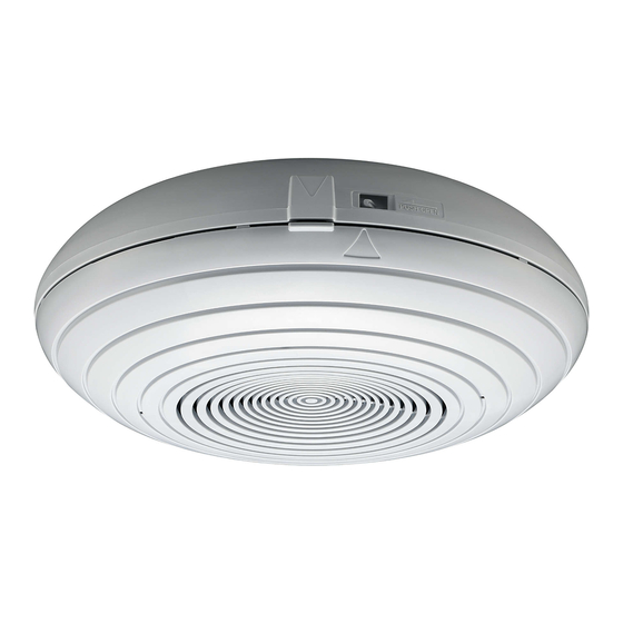
SPLASH-PROOF CEILING SPEAKER
Speaker
TABLE OF CONTENTS
1. SAFETY PRECAUTIONS .................................................. 2
2. GENERAL DESCRIPTION AND FEATURES ................... 4
3. NOMENCLATURE ............................................................ 4
4.1. Installation Precautions ............................................... 5
4.2. Before Installation ....................................................... 5
4.3. Installation procedure ................................................. 6
4.4. Removing the Front Case ......................................... 11
5. WIRING DIAGRAM ......................................................... 12
6. SPECIFICATIONS ........................................................... 12
Accessories ..................................................................... 12
Thank you for purchasing TOA Splash-proof Ceiling Speaker.
Please carefully follow the instructions in this manual to ensure long, trouble-free use of your equipment.
INSTRUCTION MANUAL
PC-2268WP
Knob nuts
(accessory)
Speaker mounting panel
(accessory)
Advertisement
Table of Contents

Related Manuals for Toa PC-2268WP


Summary of Contents for Toa PC-2268WP
-
Page 1: Table Of Contents
4.4. Removing the Front Case ......... 11 5. WIRING DIAGRAM ............12 6. SPECIFICATIONS ............12 Accessories ..............12 Thank you for purchasing TOA Splash-proof Ceiling Speaker. Please carefully follow the instructions in this manual to ensure long, trouble-free use of your equipment. -
Page 2: Safety Precautions
· If water or any metallic object gets into the speaker · If the speaker falls, or the speaker case breaks • To prevent a fire or electric shock, never open nor remove the speaker case. Refer all servicing to your nearest TOA dealer. - Page 3 Indicates a potentially hazardous situation which, if mishandled, could CAUTION result in moderate or minor personal injury, and/or property damage. When Installing the Unit • To avoid electric shocks, be sure to switch off the amplifier's power when connecting speakers. •...
-
Page 4: General Description And Features
2. GENERAL DESCRIPTION AND FEATURES The PC-2268WP is a splash-proof surface mount ceiling speaker with rated input of 6 W (100 V line application). It meets IPX4 water protection requirements and can be installed in locations where it may not be directly exposed to wind and rain. -
Page 5: Installation
4. INSTALLATION 4.1. Installation Precautions • Although the unit meets IPX4 water protection requirements, it is not completely water resistant. Avoid installing it in locations where it may be directly exposed to wind and rain. If rainwater could enter inside the unit, the aging of parts may cause the unit failure. -
Page 6: Installation Procedure
4.3. Installation procedure Step 1. Apply caulking compound correctly over the mounting surface of the speaker mounting panel (accessory) or an electrical box to ensure waterproof integrity. 1-1. When installing the speaker mounting panel directly to a ceiling (Refer to the figure below.); Be sure to follow the same waterproof treatment described below when attaching the panel to an electrical box installed behind the ceiling. - Page 7 2-2. When installing the speaker mounting panel to an exposed electrical box (Refer to the figure below.); Caulking treatment Note Be sure to waterproof the joint of the cable conduit and electrical box. Exposed electrical box Caulking compound Exposed electrical box Cable conduit Cable entry hole Speaker mounting panel dimensional diagram...
- Page 8 Step 3. Route the speaker cables through a cable entry opening (ø30 mm) in the rear case, then secure the rear case to the speaker mounting panel with the supplied knob nuts. The knob nut can be finger- tightened. Exposed electrical box Ceiling Speaker mounting panel Speaker mounting panel...
- Page 9 Step 4. Connect the speaker cables to the input terminal. Connect both the input line (cable from the amplifier) and bridge line (cable to the next speaker) to the input terminal. Reinforcement bracket Rear case secured to the ceiling Bind the speaker cables to the reinforcement bracket using its idle holes with the cable ties (2 places).
- Page 10 Step 5. Set the input tap. Disconnect the black lead (HOT) connected to the matching transformer, then connect it to the desired input tap. Matching transformer is installed inside the front case. Impedance 1.7 kΩ 3.3 kΩ 6.7 kΩ 13 kΩ 100 V line 1.5 W 0.8 W...
-
Page 11: Removing The Front Case
Step 8. Secure the front case to the rear case. 8-1. Align the positioning mark on the front case ( ) with that on the rear case, then insert the front case to the rear case. Confirm that the cables are not pinched between the cases and that speaker cables do not touch the components inside the speaker. -
Page 12: Wiring Diagram
Note: The design and specifications are subject to change without notice for improvement. • Accessories Speaker mounting panel ......1 Knob nut ............. 2 Tapping screw (4 x 35) ....... 2 Machine screw (M4 x 35) ......2 URL: http://www.toa.jp/ 533-06-206-9A...
Need help?
Do you have a question about the PC-2268WP and is the answer not in the manual?
Questions and answers