Table of Contents
Advertisement
Quick Links
Advertisement
Table of Contents

Related Manuals for Supero X9SCM


Summary of Contents for Supero X9SCM
- Page 1 X9SCM X9SCM-F X9SCL X9SCL-F USER’S MANUAL Revision 1.0a...
- Page 2 This product, including software and docu- mentation, is the property of Supermicro and/or its licensors, and is supplied only under a license. Any use or reproduction of this product is not allowed, except as expressly permitted by the terms of said license.
-
Page 3: About This Motherboard
X9SCM/X9SCM-F/X9SCL/X9SCL-F supports a single Intel® Xeon E3-1200 series, 2nd generation Intel Core® i3, Pentium®, Celeron® processor in an LGA 1155 socket. With the Intel® Cougar Point chipset built in, the X9SCM/ X9SCL series motherboard offers substantial enhancement in system performance and storage capability for entry-level to mid-range servers in a sleek package. -
Page 4: Conventions Used In This Manual
X9SCM/X9SCM-F/X9SCL/X9SCL-F User’s Manual Conventions Used in This Manual Pay special attention to the following symbols for proper motherboard installation and to prevent damage to the system or injury to yourself: Danger/Caution: Instructions to be strictly followed to prevent catastrophic system failure or to avoid bodily injury,... -
Page 5: Contacting Supermicro
Super Micro Computer, Inc. 980 Rock Ave. San Jose, CA 95131 U.S.A. Tel: +1 (408) 503-8000 Fax: +1 (408) 503-8008 Email: marketing@supermicro.com (General Information) support@supermicro.com (Technical Support) Web Site: www.supermicro.com Europe Address: Super Micro Computer B.V. Het Sterrenbeeld 28, 5215 ML... -
Page 6: Table Of Contents
X9SCM/X9SCM-F/X9SCL/X9SCL-F User’s Manual Table of Contents Preface About This Motherboard ....................iii Manual Organization ..................... iii Conventions Used in This Manual ................iv Contacting Supermicro ....................v Chapter 1 Introduction Overview ......................1-1 Checklist ......................1-1 Motherboard Features ..................1-7 Chipset Overview ..................1-10 Intel C202/C204 Express Chipset Features .......... - Page 7 Table of Contents Memory Population Guidelines ..............2-11 Motherboard Installation ................2-13 Tools Needed ....................2-13 Location of Mounting Holes ................2-13 Installing the Motherboard ................2-14 Connectors/IO Ports ..................2-15 Backplane I/O Panel ..................2-15 ATX PS/2 Keyboard/Mouse Ports ............2-16 Universal Serial Bus (USB) ..............
- Page 8 X9SCM/X9SCM-F/X9SCL/X9SCL-F User’s Manual Watch Dog Enable ................... 2-33 USB Wake-Up ..................2-34 BMC Enable ..................... 2-34 ME Recovery .................... 2-35 Onboard Indicators ..................2-36 LAN 1/LAN 2 LEDs .................. 2-36 IPMI Dedicated LAN LEDs ..............2-36 Onboard Power LED ......................2-37 IPMI Heartbeat LED .................
- Page 9 Table of Contents AddOn ROM Display Mode ................ 4-4 Bootup Num-Lock ..................4-4 Wait For 'F1' If Error ................... 4-4 Interrupt 19 Capture ................... 4-4 Watch Dog Function ................... 4-5 Power Button Function ................4-5 Restore on AC Power Loss ................ 4-5 VFC ......................
- Page 10 X9SCM/X9SCM-F/X9SCL/X9SCL-F User’s Manual Wake on LAN from S5 ................4-9 Legacy USB Support .................. 4-9 BIOS EHCI Hand-Off.................. 4-9 IDE/SATA Configuration ................4-9 SATA Mode ....................4-9 IDE Mode ....................4-9 Serial-ATA Controller 0~1 ................4-9 SATA Port0~Port5 ..................4-9 AHCI Mode ....................
- Page 11 Smbios Event Log ..................4-15 Erase Event Log ..................4-15 When Log is Full ..................4-15 MECI ......................4-15 METW ....................... 4-15 IPMI Configuration (X9SCL-F/X9SCM-F Only) ..........4-16 BMC Support .................... 4-16 Wait For BMC ................... 4-16 BMC Self Test Log................. 4-16 ...
- Page 12 X9SCM/X9SCM-F/X9SCL/X9SCL-F User’s Manual Appendix A BIOS Error Beep Codes BIOS Error Beep Codes .................A-1 Appendix B Software Installation Instructions Installing Drivers ....................B-1 Configuring Supero Doctor III .................B-2 Appendix C BIOS Recovery Recovery Process from a USB Device/Drive (Recommended Method) ..C-1 Part 1: Boot Sector Recovery Process ............C-1...
-
Page 13: Chapter 1 Introduction
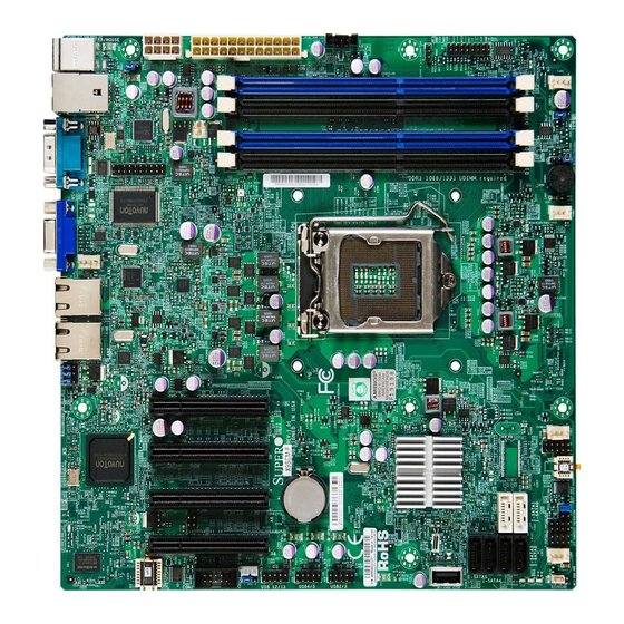
Checklist Congratulations on purchasing your computer motherboard from an acknowledged leader in the industry. Supermicro boards are designed with the utmost attention to detail to provide you with the highest standards in quality and performance. Please check that the following items have all been included with your motherboard. - Page 14 X9SCM/X9SCM-F/X9SCL/X9SCL-F User’s Manual Motherboard Image (X9SCM/X9SCM-F) Note: All graphics shown in this manual were based upon the latest PCB Revision available at the time of publishing of the manual. The motherboard you've received may or may not look exactly the same as the graphics...
- Page 15 Chapter 1: Introduction Motherboard Image (X9SCL/X9SCL-F) Note: All graphics shown in this manual were based upon the latest PCB Revision available at the time of publishing of the manual. The motherboard you've received may or may not look exactly the same as the graphics shown in this manual.
-
Page 16: Motherboard Layout
For X9SCM(-F): Two SATA-III ports (I-SATA#0~1) and four SATA-II ports (3 Gb/s, I-SATA#2~5) are located on the board. For X9SCL(-F): Six SATA-II ports (I-SATA #0~5) are included on the motherboard. • PCI-E Slot5 (PCI-E 2.0 x4 on x8 slot) is available on the X9SCM(-F) only. - Page 17 Cougar Point CTRL (For X9SCM only) Standard PCH Slot5 PCI-E 2.0 x4 on x8 Battery JI2C1 (*I-SATA 0/1: JI2C2 T-SGPIO2 X9SCL: SATA2, X9SCM: SATA3) Slot4 PCI-E 2.0 x4 on x8 T-SGPIO1 JBT1 Memory Chip JWOL COM2 FANA USB 12/13 USB4/5...
- Page 18 +12V 8-pin CPU power Connector (Required) KB/Mouse Keyboard/Mouse Connectors 8,9,3 LAN1/LAN2, IPMI_LAN Gigabit (RJ45) Ports (LAN1/2), IPMI_LAN (F-models) 50,49 I-SATA 0/1 Serial ATA Ports 0/1 (X9SCL: SATA-II Ports, X9SCM: SATA-III Ports) 27,26,25,24 I-SATA 0~5 SATA-II Ports PWR supply (I C) System Management Bus JSPK...
-
Page 19: Motherboard Features
SATA-II Ports Six (6) (I-SATA 0~5) RAID (Windows) RAID 0, 1, 5, 10 Integrated IPMI 2.0 (X9SCM-F/X9SCL-F Only) IPMI 2.0 supported by the WPCM450 Server BMC USB Devices Two (2) USB ports on the rear IO panel (USB 0/1) Six (6) USB header connectors for front access (USB... - Page 20 Drivers and software for Intel® Cougar Point chipset utilities Other ROHS 6/6 (Full Compliance, Lead Free) Dimensions Micro ATX form factor (9.6" x 9.6") (243.84mm x 243.84mm) Note: For IPMI Configuration Instructions, please refer to the Embedded IPMI Configuration User's Guide available @ http://www.supermicro.com/ support/manuals/.
-
Page 21: System Block Diagram
RJ45 5.0Gbps 2.5Gbps 82574L PCIe_x1 GLAN2 RJ45 SATA-II 6/4 SATA Ports 2.5Gbps 82579 Cougar Point 300MB/s (X9SCL/X9SCM) (*See Note below) SATA-III PCI32 Hermon WPCM450 0/2 SATA Ports 600MB/s Winbond BMC USB2.0 9 USB Ports 480Mbps RMII TPM1.2 Header RTL8201 Port... -
Page 22: Chipset Overview
Direct Media Interface (DMI) for chip-to-chip true iso- chronous communication, providing up to 10 Gb/s of software-transparent data transfer rate on each read/write direction. In addition, the X9SCM/X9SCM-F/ X9SCL/X9SCL-F also features a TCO timer which allows the system to recover from a software/hardware lock and perform tasks, including ECC Error Reporting, Function Disable and Intruder Detect. -
Page 23: Special Features
Chapter 1: Introduction Special Features Recovery from AC Power Loss Basic I/O System (BIOS) provides a setting for you to determine how the system will respond when AC power is lost and then restored to the system. You can choose for the system to remain powered off (in which case you must press the power switch to turn it back on), or for it to automatically return to a power-on state. -
Page 24: Acpi Features
X9SCM/X9SCM-F/X9SCL/X9SCL-F User’s Manual the Windows OS environment or used with Supero Doctor II in Linux. Supero Doctor is used to notify the user of certain system events. For example, you can also configure Supero Doctor to provide you with warnings when the system temperature, CPU temperatures, voltages and fan speeds go beyond predefined thresholds. -
Page 25: Super I/O
Chapter 1: Introduction 8-pin (JPW2) power connectors on the motherboard. Failure in doing so will void the manufacturer warranty on your power supply and motherboard. 2. To provide adequate power to SATA devices, please connect the SATA DOM PWR connector (JWF1) to the power supply. It is strongly recommended that you use a high quality power supply that meets ATX power supply Specification 2.02 or above. - Page 26 X9SCM/X9SCM-F/X9SCL/X9SCL-F User’s Manual Notes 1-14...
-
Page 27: Chapter 2 Installation
Chapter 2: Installation Chapter 2 Installation Static-Sensitive Devices Electrostatic-Discharge (ESD) can damage electronic com ponents. To avoid dam- aging your system board, it is important to handle it very carefully. The following measures are generally sufficient to protect your equipment from ESD. Precautions •... -
Page 28: Processor And Heatsink Installation
CPU socket cap is in place and none of the socket pins are bent; otherwise, contact your retailer immediately. Refer to the Supermicro website for updates on CPU support. Installing the LGA1155 Processor Press the load lever to release the load plate, which covers the CPU socket, from its locking position. - Page 29 Chapter 2: Installation Gently lift the load lever to open the load plate. Remove the plastic cap. Use your thumb and your index finger to hold the CPU at the North center edge and the South center edge of the CPU. North Center Edge South Center Edge Align the CPU key that is the semi-circle cutouts against the socket keys.
- Page 30 X9SCM/X9SCM-F/X9SCL/X9SCL-F User's Manual Do not rub the CPU against the surface or against any pins of the socket to avoid damaging the CPU or the socket.) With the CPU inside the socket, inspect the four corners of the CPU to make sure that the CPU is properly installed.
-
Page 31: Installing A Passive Cpu Heatsink
Screw in two diagonal screws (i.e., the #1 and the #2 screws) until just snug (-do not over-tighten the screws to avoid possible damage to the CPU.) Finish the installation by fully tightening all four screws. Screw#1 Screw#2 Motherboard Mounting Holes Recommended Supermicro heatsink: SNK-P0046P heatsink with BKT- 0028L bottom bracket Heatsink Bracket... -
Page 32: Removing The Heatsink
X9SCM/X9SCM-F/X9SCL/X9SCL-F User's Manual Removing the Heatsink Warning: We do not recommend that the CPU or the heatsink be removed. However, if you do need to uninstall the heatsink, please follow the instruc- tions below to uninstall the heatsink to prevent damage done to the CPU or the CPU socket. -
Page 33: Installing An Active Fan Cpu Heatsink
If necessary, rearrange the wires to make sure that the wires are not pinched between the heatsink and the CPU. Also make sure to keep Recommended Supermicro heatsink: clearance between the fan wires SNK-P0046A4 active heatsink and the fins of the heatsink. - Page 34 X9SCM/X9SCM-F/X9SCL/X9SCL-F User's Manual Align the four heatsink fasten- ers with the mounting holes on the motherboard. Gently push the pairs of diagonal fasteners (#1 & #2, and #3 & #4) into the mounting holes until you hear a click. Also,...
-
Page 35: Removing The Heatsink
Chapter 2: Installation Removing the Heatsink Warning: We do not recommend that the CPU or the heatsink be removed. However, if you do need to remove the heatsink, please follow the instructions be- low to remove the heatsink and to prevent damage done to the CPU or other components. -
Page 36: Installing Ddr3 Memory
X9SCM/X9SCM-F/X9SCL/X9SCL-F User's Manual Installing DDR3 Memory Note: Check the Supermicro website for recommended memory mod- ules. CAUTION Exercise extreme care when installing or removing DIMM modules to prevent any possible damage. DIMM Installation Insert the desired number of DIMMs into the memory slots, starting with DIMM1A (Slot 1, Channel 1). -
Page 37: Memory Support
Chapter 2: Installation Memory Support The X9SCM(-F)/X9SCL(-F) series supports up to 32GB of Unbuffered (UDIMM) DDR3 ECC 1333/1066 MHz in 4 memory slots. Populating these DIMM modules with a pair of memory modules of the same type and same size will result in... - Page 38 X9SCM/X9SCM-F/X9SCL/X9SCL-F User's Manual For Microsoft Windows users: Microsoft implemented a design change in the Win- dows XP with Service Pack 2 (SP2) and Windows Vista. This change is specific to the behavior of Physical Address Extension (PAE) mode which improves driver compatibility.
-
Page 39: Motherboard Installation
Philips Screwdriver Philips Screwdriver Standoffs Location of Mounting Holes X9SCM/X9SCL(-F) Rev.1.0 Caution: 1) To prevent damage to the motherboard and its components, please do not use a force greater than 8 lb/inch on each mounting screw during motherboard installation. 2) Some components are very close to the mounting holes. -
Page 40: Installing The Motherboard
X9SCM/X9SCM-F/X9SCL/X9SCL-F User's Manual Installing the Motherboard Install the I/O shield into the chassis. Locate the mounting holes on the motherboard. Locate the matching mounting holes on the chassis. Align the mounting holes on the motherboard against the mounting holes on the chassis. -
Page 41: Connectors/Io Ports
I/O ports. Backplane I/O Panel X9SCM/X9SCL(-F) Rev.1.0 Backplane I/O Panel 1. Keyboard (Purple) 6. COM 1 2. PS/2 Mouse (Green) 7. VGA 3. USB Port 0 8. LAN1 4. USB Port 1 9. LAN2 5. IPMI LAN (X9SCM-F/X9SCL-F Only) 2-15... -
Page 42: Atx Ps/2 Keyboard/Mouse Ports
X9SCM/X9SCM-F/X9SCL/X9SCL-F User's Manual ATX PS/2 Keyboard/Mouse PS/2 Keyboard/Mouse Pin Ports Definitions PS2 Keyboard PS2 Mouse The ATX PS/2 keyboard and Pin# Definition Pin# Definition PS/2 mouse are located next to KB Data Mouse Data the Back Panel USB Ports 0/1 on... -
Page 43: Universal Serial Bus (Usb)
USB_PN3 USB_PP2 USB_PP3 Ground Ground No Con- nection 1. Backpanel USB 0 2. Backpanel USB 1 3. Front Panel USB 2/3 4. Front Panel USB 4/5 5. Front Panel USB 12/13 6. Internal 'Type A' USB 11 X9SCM/X9SCL(-F) Rev.1.0 2-17... -
Page 44: Ethernet Ports
I/O Backpanel. In addition, an IPMI TD0+ P3V3SB Dedicated LAN is also located above TD1- Act LED USB 0/1 ports on the X9SCM-F/X9S- TD1+ Link 100 LED CL-F to provide a dedicated network (Green, +3V3SB) connection for IPMI 2.0. These ports... -
Page 45: Serial Ports
Pin # Definition Pin # Definition the I/O backpanel, and another Serial Connection (COM2) is located below PCI-E Slot4 to provide front access. See the table on the right for pin definitions. Ground 1. COM1 2. COM2 X9SCM/X9SCL(-F) Rev.1.0 2-19... -
Page 46: Video Connector
X9SCM/X9SCM-F/X9SCL/X9SCL-F User's Manual Video Connector VGA/CRT Pin Definitions A Video (VGA) connector is located Pin# Definition Pin# Definition next to the COM Port on the I/O Ground backpanel. This connector is used Green to provide video and CRT display. Blue... -
Page 47: Front Control Panel
These connectors are designed specifically for use with Supermicro server chassis. See the figure below for the descriptions of the various control panel buttons and LED indicators. Refer to the following section for descriptions and pin definitions. -
Page 48: Front Control Panel Pin Definitions
X9SCM/X9SCM-F/X9SCL/X9SCL-F User's Manual Front Control Panel Pin Definitions Power LED Power LED Pin Definitions (JF1) The Power LED connection is located Pin# Definition on pins 15 and 16 of JF1. Refer to the 3.3V/vcc table on the right for pin definitions. Ground HDD LED The HDD LED connection is located... -
Page 49: Nic1/Nic2 (Lan1/Lan2)
Chapter 2: Installation NIC1/NIC2 (LAN1/LAN2) LAN1/LAN2 LED Pin Definitions (JF1) The NIC (Network Interface Controller) Pin# Definition LED connection for LAN port 1 is located 9/11 on pins 11 and 12 of JF1, and the LED 10/12 LAN Active connection for LAN Port 2 is on Pins 9 and 10. -
Page 50: Reset Button
X9SCM/X9SCM-F/X9SCL/X9SCL-F User's Manual Reset Button Reset Button The Reset Button connection is located Pin Definitions (JF1) on pins 3 and 4 of JF1. Attach it to a Pin# Definition hardware reset switch on the computer Reset case to reset the system. Refer to the Ground table on the right for pin definitions. -
Page 51: Connecting Cables
Cougar Point CTRL (For X9SCM only) Standard PCH Slot5 PCI-E 2.0 x4 on x8 Battery JI2C1 (*I-SATA 0/1: JI2C2 T-SGPIO2 X9SCL: SATA2, X9SCM: SATA3) Slot4 PCI-E 2.0 x4 on x8 T-SGPIO1 JBT1 Memory Chip COM2 JWOL FANA USB 12/13 USB4/5... -
Page 52: Fan Headers
Cougar Point CTRL (For X9SCM only) Standard PCH Slot5 PCI-E 2.0 x4 on x8 Battery JI2C1 (*I-SATA 0/1: JI2C2 T-SGPIO2 X9SCL: SATA2, X9SCM: SATA3) Slot4 PCI-E 2.0 x4 on x8 T-SGPIO1 JBT1 Memory Chip COM2 JWOL FANA USB 12/13 USB4/5... -
Page 53: Internal Buzzer
Cougar Point CTRL (For X9SCM only) Standard PCH Slot5 PCI-E 2.0 x4 on x8 Battery JI2C1 (*I-SATA 0/1: JI2C2 T-SGPIO2 X9SCL: SATA2, X9SCM: SATA3) Slot4 PCI-E 2.0 x4 on x8 T-SGPIO1 JBT1 Memory Chip COM2 JWOL FANA USB 12/13 USB4/5... -
Page 54: Onboard Power Led
Cougar Point CTRL (For X9SCM only) Standard PCH Slot5 PCI-E 2.0 x4 on x8 Battery JI2C1 (*I-SATA 0/1: JI2C2 T-SGPIO2 X9SCL: SATA2, X9SCM: SATA3) Slot4 PCI-E 2.0 x4 on x8 T-SGPIO1 JBT1 Memory Chip COM2 JWOL FANA USB 12/13 USB4/5... -
Page 55: T-Sgpio 0/1 Headers
Cougar Point CTRL (For X9SCM only) Standard PCH Slot5 PCI-E 2.0 x4 on x8 Battery JI2C1 (*I-SATA 0/1: JI2C2 T-SGPIO2 X9SCL: SATA2, X9SCM: SATA3) Slot4 PCI-E 2.0 x4 on x8 T-SGPIO1 JBT1 Memory Chip COM2 JWOL FANA USB 12/13 USB4/5... -
Page 56: Dom Pwr Connector
Cougar Point CTRL (For X9SCM only) Standard PCH Slot5 PCI-E 2.0 x4 on x8 Battery JI2C1 (*I-SATA 0/1: JI2C2 T-SGPIO2 X9SCL: SATA2, X9SCM: SATA3) Slot4 PCI-E 2.0 x4 on x8 T-SGPIO1 JBT1 Memory Chip COM2 JWOL FANA USB 12/13 USB4/5... -
Page 57: Jumper Settings
CTRL (For X9SCM only) Standard PCH Slot5 PCI-E 2.0 x4 on x8 Battery JI2C1 (*I-SATA 0/1: JI2C2 T-SGPIO2 Slot4 PCI-E 2.0 x4 on x8 X9SCL: SATA2, X9SCM: SATA3) T-SGPIO1 Memory Chip JBT1 COM2 JWOL FANA USB 12/13 USB4/5 USB2/3 JPG1... -
Page 58: Cmos Clear
Cougar Point CTRL (For X9SCM only) Standard PCH Slot5 PCI-E 2.0 x4 on x8 Battery JI2C1 (*I-SATA 0/1: JI2C2 T-SGPIO2 X9SCL: SATA2, X9SCM: SATA3) Slot4 PCI-E 2.0 x4 on x8 T-SGPIO1 JBT1 Memory Chip COM2 JWOL FANA USB 12/13 USB4/5... -
Page 59: Vga Enable
Cougar Point CTRL (For X9SCM only) Standard PCH Slot5 PCI-E 2.0 x4 on x8 Battery JI2C1 (*I-SATA 0/1: JI2C2 T-SGPIO2 X9SCL: SATA2, X9SCM: SATA3) Slot4 PCI-E 2.0 x4 on x8 T-SGPIO1 JBT1 Memory Chip COM2 JWOL FANA USB 12/13 USB4/5... -
Page 60: Usb Wake-Up
Cougar Point CTRL (For X9SCM only) Standard PCH Slot5 PCI-E 2.0 x4 on x8 Battery JI2C1 (*I-SATA 0/1: JI2C2 T-SGPIO2 X9SCL: SATA2, X9SCM: SATA3) Slot4 PCI-E 2.0 x4 on x8 T-SGPIO1 JBT1 Memory Chip COM2 JWOL FANA USB 12/13 USB4/5... -
Page 61: Me Recovery
Cougar Point CTRL (For X9SCM only) Standard PCH Slot5 PCI-E 2.0 x4 on x8 Battery JI2C1 (*I-SATA 0/1: JI2C2 T-SGPIO2 X9SCL: SATA2, X9SCM: SATA3) Slot4 PCI-E 2.0 x4 on x8 T-SGPIO1 Memory Chip JBT1 COM2 JWOL FANA USB 12/13 USB4/5... -
Page 62: Onboard Indicators
IPMI LAN Link LED (Left) & Activity LED (Right) In addition to LAN 1/LAN 2, an IPMI Dedi- Status Color Definition cated LAN is also located on the X9SCM-F/ Link (Left) Green: Solid 100 Mbps X9SCL-F. The yellow LED on the right Activity... -
Page 63: Onboard Power Led
Cougar Point CTRL (For X9SCM only) Standard PCH Slot5 PCI-E 2.0 x4 on x8 Battery JI2C1 (*I-SATA 0/1: JI2C2 T-SGPIO2 X9SCL: SATA2, X9SCM: SATA3) Slot4 PCI-E 2.0 x4 on x8 T-SGPIO1 JBT1 Memory Chip COM2 JWOL FANA USB 12/13 USB4/5... -
Page 64: Sata Connections
SATA Connections Six Serial ATA (SATA) connectors (I-SATA 0~5) are located on the motherboard. For the X9SCM series, I-SATA Ports 0/1 support SATA-III, and I-SATA Ports 2~5 support SATA-II. For the X9SCL models, all SATA ports support SATAII. These Serial Link connections provide faster data transmission than legacy Parallel ATA. -
Page 65: Chapter 3 Troubleshooting
Chapter 3: Troubleshooting Chapter 3 Troubleshooting Troubleshooting Procedures Use the following procedures to troubleshoot your system. If you have followed all of the procedures below and still need assistance, refer to the ‘Technical Support Procedures’ and/or ‘Returning Merchandise for Service’ section(s) in this chapter. Always disconnect the AC power cord before adding, changing or installing any hardware components. -
Page 66: No Video
X9SCM/X9SCM-F/X9SCL/X9SCL-F User's Manual No Video If the power is on, but you have no video--in this case, you will need to re- move all the add-on cards and cables first. Use the speaker to determine if any beep codes exist. (Refer to Appendix A for details on beep codes.) -
Page 67: Technical Support Procedures
Before contacting Technical Support, please make sure that you have followed all the steps listed below. Also, Note that as a motherboard manufacturer, Supermicro does not sell directly to end users, so it is best to first check with your distributor or reseller for troubleshooting services. -
Page 68: Frequently Asked Questions
Note: Always use the file named “ami.bat” to update the BIOS, and insert a space between "ami.bat" and the filename. The BIOS-ROM-filename will bear the motherboard name (i.e., X9SCM) and build version as the extension. For example, "X9SCM0.115".When completed, your system will automatically reboot. - Page 69 Question: Why do I get an error message “IASTOR.SYS read error” and "press F6 to install Intel RAID driver" when installing Windows on my motherboard? Question: What is the heatsink part number for my X9SCM/X9SCM-F/X9SCL/ X9SCL-F motherboard? Answer: For the 1U passive heatsink, ask for SNK-P0046P (back plate is included).
-
Page 70: Battery Removal And Installation
X9SCM/X9SCM-F/X9SCL/X9SCL-F User's Manual Battery Removal and Installation Battery Removal To remove the onboard battery, follow the steps below: Power off your system and unplug your power cable. Locate the onboard battery as shown below. Using a tool such as a pen or a small screwdriver, push the battery lock out- wards to unlock it. -
Page 71: Returning Merchandise For Service
You can obtain service by calling your vendor for a Returned Merchandise Authorization (RMA) number. For faster service, you may also obtain RMA authorizations online (http://www.supermicro. com/support/rma/). When you return the motherboard to the manufacturer, the RMA number should be prominently displayed on the outside of the shipping carton, and mailed prepaid or hand-carried. - Page 72 X9SCM/X9SCM-F/X9SCL/X9SCL-F User's Manual Notes...
-
Page 73: Chapter 4 Bios
When an option is selected in the left frame, it is highlighted in white. Often a text message will accompany it. (Note: the AMI BIOS has default text messages built in. Supermicro retains the option to include, omit, or change any of these text messages.) The AMI BIOS Setup Utility uses a key-based navigation system called "hot keys". -
Page 74: How To Start The Setup Utility
Warning! Do not upgrade the BIOS unless your system has a BIOS-related issue. Flashing the wrong BIOS can cause irreparable damage to the system. In no event shall Supermicro be liable for direct, indirect, special, incidental, or consequential damages arising from a BIOS update. If you have to update the BIOS, do not shut down or reset the system while the BIOS is updating. -
Page 75: System Overview: The Following Bios Information Will Be Displayed
<Tab> key or the arrow keys to move between fields. The date must be entered in Day MM/DD/YY format. The time is entered in HH:MM:SS format. (Note: The time is in the 24-hour format. For example, 5:30 P.M. appears as 17:30:00.) Supermicro X9SCM/X9SCM-F/X9SCL/X9SCL-F Version Build Date... -
Page 76: 4-3 Advanced Setup Configurations
X9SCM/X9SCM-F/X9SCL/X9SCL-F 4-3 Advanced Setup Configurations Use the arrow keys to select Boot Setup and hit <Enter> to access the submenu items: BOOT Feature Quiet Boot This option allows the bootup screen options to be modified between POST mes- sages or the OEM logo. Select Disabled to display the POST messages. Select Enabled to display the OEM logo instead of the normal POST messages. -
Page 77: Watch Dog Function
Chapter 4: AMI BIOS 19 at boot and allow the drives that are attached to these host adaptors to function as bootable disks. If this item is set to Disabled, the ROM BIOS of the host adap- tors will not capture Interrupt 19, and the drives attached to these adaptors will not function as bootable devices. -
Page 78: Adjacent Cache Line Prefetch (Available When Supported By The Cpu)
X9SCM/X9SCM-F/X9SCL/X9SCL-F Adjacent Cache Line Prefetch (Available when supported by the CPU) The CPU fetches the cache line for 64 bytes if this option is set to Disabled. The CPU fetches both cache lines for 128 bytes as comprised if Enabled. -
Page 79: P-State Coordination
Chapter 4: AMI BIOS P-STATE Coordination This feature selects the type of coordination for the P-State of the processor. P-State is a processor operational state that reduces the processor's voltage and frequency. This makes the processor more energy effiicient, resulting in further gains. -
Page 80: North Bridge Configuration
X9SCM/X9SCM-F/X9SCL/X9SCL-F North Bridge Configuration This item displays the current North Bridge Revision. VT-d Select Enabled to enable Intel's Virtualization Technology support for Direct I/O VT-d by reporting the I/O device assignments to VMM through the DMAR ACPI Tables. This feature offers fully-protected I/O resource- sharing across the Intel platforms, providing the user with greater reliabil- ity, security and availability in networking and data-sharing. -
Page 81: Wake On Lan From S5
Chapter 4: AMI BIOS Wake on LAN from S5 Select Enabled to enable the capabiltiy to 'wake-up' the system from the S5 power state (Soft Off State) through the Ethernet controller. The set- tings are Enabled and Disabled. Legacy USB Support This feature enables support for legacy USB devices. -
Page 82: Aggressive Link Power Management
X9SCM/X9SCM-F/X9SCL/X9SCL-F Aggressive Link Power Management This feature Enables or Disables Agressive Link Power Management support for Cougar Point B0 stepping and later. The options are Enabled and Disabled. SATA Port0~Port5 This item displays the information detected on the installed SATA drives on the particular SATA port. -
Page 83: Pci Latency Timer
Chapter 4: AMI BIOS PCI Latency Timer This feature sets the latency Timer of each PCI device installed on a PCI bus. Select 64 to set the PCI latency to 64 PCI clock cycles. The options are 32, 64, 96, 128, 160, 192, 224 and 248. -
Page 84: Remote Access Configuration
X9SCM/X9SCM-F/X9SCL/X9SCL-F Serial Port 2 Mode Use this feature to configure Serial Port 2 mode. The options are Normal, IrDA and ASK IR. IrDA (Infrared Data) is an industry standard for remote control devices. ASK IR (Amplitude Shifted Keying Infrared) is a protocol compatible with Sharp® branded PDAs and other infrared devices. -
Page 85: Hardware Health Configuration
Chapter 4: AMI BIOS Data Bits: 8 or 7 Parity: None, Even, Odd, Mark, or Space Stop Bits: 1 or 2 Hardware Health Configuration Fan Speed Control Mode This feature allows the user to decide how the system controls the speeds of the onboard fans. -
Page 86: Fan1 ~ Fan4, Fana Reading
X9SCM/X9SCM-F/X9SCL/X9SCL-F User intervention: No action is required. However, consider checking the CPU fans and the chassis ventilation for blockage. High – The processor is running hot. This is a ‘caution’ level since the CPU’s ‘Temperature Tolerance’ has been reached (or has been exceeded) and may activate an overheat alarm: The information provided above is for your reference only. -
Page 87: Event Logs
Chapter 4: AMI BIOS Event Logs Smbios Event Log Change this item to enable or disable all features of the Smbios Event Logging during boot. The options are Enabled and Disabled. Erase Event Log This option erases all logged events. The options are No, Yes, Next reset and Yes, Every reset. -
Page 88: Ipmi Configuration (X9Scl-F/X9Scm-F Only)
X9SCM/X9SCM-F/X9SCL/X9SCL-F 4-5 IPMI Configuration (X9SCL-F/X9SCM-F Only) Intelligent Platform Management Interface (IPMI) is a set of common interfaces that IT administrators can use to monitor system health and to manage the system as a whole. For more information on the IPMI specifications, please visit Intel's website at www.intel.com. -
Page 89: When Sel Full
Chapter 4: AMI BIOS SEL Components - Change this item to enable or disable all features of System Event Logging. The options are Enabled and Disabled. When Enabled, the following can be configured: Erase SEL - This option erases all logged SEL events. The options are No, Yes, On Next reset and Yes, On Every reset. -
Page 90: Boot Settings
X9SCM/X9SCM-F/X9SCL/X9SCL-F Boot Settings Use this feature to configure Boot Settings: Boot Options Priority This feature allows the user to specify which devices are boot devices and the order of priority from which the systems boots from during startup. Boot Option #1, Boot option #2, Boot Option #3, etc The settings are Built-in EFI Shell, [any detected boot device] and Disabled. -
Page 91: Security Settings
Chapter 4: AMI BIOS Security Settings • If the Administrator password is defined ONLY - this controls access to the BIOS setup ONLY. • If the User's password is defined ONLY - this password will need to be entered during each system startup or boot, and will also have Administrator rights in the setup. -
Page 92: Exit Options
X9SCM/X9SCM-F/X9SCL/X9SCL-F Exit Options Select the Exit tab from the BIOS Setup Utility screen to enter the Exit BIOS Setup screen. Save Changes and Exit When you have completed the system configuration changes, select this option to leave the BIOS Setup Utility and reboot the computer, so the new system con- figuration parameters can take effect. -
Page 93: Save As User Defaults
Chapter 4: AMI BIOS Save As User Defaults To set this feature, select Save as User Defaults from the Exit menu and press <En- ter>. This enables the user to save any changes to the BIOS setup for future use Restore User Defaults To set this feature, select Restore User Defaults from the Exit menu and press <En- ter>. - Page 94 X9SCM/X9SCM-F/X9SCL/X9SCL-F Notes 4-22...
-
Page 95: Appendix A Bios Error Beep Codes
Appendix A: POST Error Beep Codes Appendix A BIOS Error Beep Codes During the POST (Power-On Self-Test) routines, which are performed each time the system is powered on, errors may occur. Non-fatal errors are those which, in most cases, allow the system to continue with bootup. - Page 96 X9SCM/X9SCM-F/X9SCL/X9SCL-F User's Manual Notes...
-
Page 97: Appendix B Software Installation Instructions
To install these software programs and drivers, click the icons to the right of these items. (Note: To install the Windows Operating System, please refer to the instructions posted on our website at http://www.supermicro.com/ support/manuals/.) Driver/Tool Installation Display Screen Note 1. -
Page 98: Configuring Supero Doctor Iii
X9SCM/X9SCM-F/X9SCL/X9SCL-F User's Manual B-2 Configuring Supero Doctor III The Supero Doctor III program is a Web-based management tool that supports remote management capability. It includes Remote and Local Management tools. The local management is called the SD III Client. The Supero Doctor III program included on the CDROM that came with your baseboard allows you to monitor the environment and operations of your system. - Page 99 Supero Doctor III Interface Display Screen-II (Remote Control) Note: SD III Software Revision 1.0 can be downloaded from our Web- site at: ftp://ftp.Supermicro.com/utility/Supero_Doctor_III/. You can also download SDIII User's Guide at: http://www.supermicro.com/PRODUCT/ Manuals/SDIII/UserGuide.pdf. For Linux, we will still recommend that you...
- Page 100 X9SCM/X9SCM-F/X9SCL/X9SCL-F User's Manual Notes...
-
Page 101: Appendix C Bios Recovery
The recovery procedure described in this section is to be used only when you are advised by your Supermicro Technical Support representative, or in cases of emergencies where the system no longer can boot due to a corrupted BIOS. DO NOT reprogram (re-flash) the BIOS if your system is running properly. -
Page 102: Part 2: Bios Reprogramming (Re-Flashing
X9SCM/X9SCM-F/X9SCL/X9SCL-F User’s Manual Part 2: BIOS Reprogramming (Re-Flashing) After completing the Boot Sector Recovery Process, you will need to reprogram (“re-flash”) the proper BIOS binary file again into the BIOS ROM in order to have the correct BIOS file loaded by the system. For details on how to flash/re-flash a BIOS, please check our website for “Update your BIOS”, or see the section 3-3... - Page 103 (Disclaimer Continued) The products sold by Supermicro are not intended for and will not be used in life support systems, medical equipment, nuclear facilities or systems, aircraft, aircraft devices, aircraft/emergency communication devices or other critical systems whose failure to perform be reasonably expected to result in significant injury or loss of life or catastrophic property damage.
Need help?
Do you have a question about the X9SCM and is the answer not in the manual?
Questions and answers