Table of Contents
Advertisement
Quick Links
Advertisement
Table of Contents

Related Manuals for Supero X9SRH-7F


Summary of Contents for Supero X9SRH-7F
- Page 1 X9SRH-7F X9SRH-7TF USER’S MANUAL Revision 1.0a...
- Page 2 The information in this User’s Manual has been carefully reviewed and is believed to be accurate. The vendor assumes no responsibility for any inaccuracies that may be contained in this document, makes no commitment to update or to keep current the information in this manual, or to notify any person or organization of the updates.
-
Page 3: About This Motherboard
Preface Preface This manual is written for system integrators, IT technicians and knowledgeable end users. It provides information for the installation and use of the X9SRH Motherboard Series motherboard. About This Motherboard X9SRH Motherboard Series supports a single Intel ® E5-1600/E5-2600 series processor (2011-pin, Socket R). -
Page 4: Conventions Used In The Manual
X9SRH Motherboard Series User’s Manual Conventions Used in the Manual: Special attention should be given to the following symbols for proper installation and to prevent damage done to the components or injury to yourself: Danger/Caution: Instructions to be strictly followed to prevent catastrophic system failure or to avoid bodily injury Warning: Critical information to prevent damage to the components or data loss. -
Page 5: Contacting Supermicro
Contacting Supermicro Contacting Supermicro Headquarters Address: Super Micro Computer, Inc. 980 Rock Ave. San Jose, CA 95131 U.S.A. Tel: +1 (408) 503-8000 Fax: +1 (408) 503-8008 Email: marketing@supermicro.com (General Information) support@supermicro.com (Technical Support) Website: www.supermicro.com Europe Address: Super Micro Computer B.V. Het Sterrenbeeld 28, 5215 ML 's-Hertogenbosch, The Netherlands Tel:... -
Page 6: Table Of Contents
X9SRH Motherboard Series User’s Manual Table of Contents Preface About This Motherboard ....................iii Manual Organization ..................... iii Conventions Used in the Manual: .................iv Safety Information ......................iv Contacting Supermicro ....................v Chapter 1 Introduction Overview ......................1-1 Checklist ......................1-1 Motherboard Features ..................1-7 Chipset Overview ..................1-11 Intel C602J Chipset Series Features .............1-11 Special Features ................... - Page 7 Table of Contents Memory Population Guidelines ..............2-11 Motherboard Installation ................2-12 Tools Needed ....................2-12 Location of Mounting Holes ................2-12 Installing the Motherboard ................2-13 Connectors/IO Ports ..................2-14 Motherboard I/O Backpanel ................2-14 ATX PS/2 Keyboard/Mouse Ports ............2-15 Universal Serial Bus (USB) ..............
- Page 8 X9SRH Motherboard Series User’s Manual Explanation of Jumpers ................2-32 LAN Port Enable/Disable (JPL1~2) ............2-32 CMOS Clear (JBT1) ................. 2-33 PCI-E Slot SMB Enable (JI2C1/JI2C2) ............ 2-33 VGA Enable (JPG1) ................. 2-34 Watch Dog Reset (JWD1) ................ 2-34 USB Wake-Up (JPUSB1) ................. 2-35 BMC Enable/Disable (JPB1) ..............
- Page 9 Table of Contents System Date/System Time ................ 4-3 Supermicro X9SRH-7F/7TF ............... 4-3 Memory Information ................... 4-3 Total Memory ....................4-3 4-3 Advanced Setup Configurations..............4-4 BOOT Feature ....................4-4 Quiet Boot ....................4-4 AddOn ROM Display Mode ................ 4-4 Bootup Num-Lock ..................4-4 Wait For 'F1' If Error ...................
- Page 10 X9SRH Motherboard Series User’s Manual Integrated IO Configuration ..............4-8 Intel VT-d ....................4-8 ® Intel I/OAT ....................4-8 ® DCA Support ....................4-8 MMCFG BASE ................... 4-9 IIO 1 PCIe Port Bifurcation Control ............4-9 CPU1 Slot 3 PCI-E 3.0 x8 (in x16) Link Speed ......... 4-9 CPU1 Slot 6 PCI-E 3.0 x16 Link Speed ............
- Page 11 Slot1 PCI 33MHZ OPROM Slot2 PCI 33MHZ OPROM CPU1 Slot3 PCI-E 3.0 x8 (in x16) OPROM Slot4 PCI 33MHz OPROM (X9SRH-7F only) PCH Slot5 PCI-E 2.0 x4 OPROM CPU1 Slot6 PCI-E 3.0 x16 OPROM ............4-14 Onboard LAN Option ROM Select ............4-14 Load Onboard LAN1 Option ROM / Load Onboard LAN2 Option ROM .
- Page 12 X9SRH Motherboard Series User’s Manual Link Speed ....................4-19 Wake On LAN ..................4-19 Blink LEDs (Range 0-15 seconds) ............4-19 Port Configuration Information ..............4-19 Event Logs ....................4-20 Change SmBIOS Event Log Settings ............4-20 Smbios Event Log ..................4-20 Runtime Error Logging Support ...............
- Page 13 Table of Contents Appendix A BIOS Error Beep Codes BIOS Error Beep Codes .................A-1 Appendix B Software Installation Instructions Installing Drivers ....................B-1 B-2 Configuring SuperDoctor ® III ................B-2 Appendix C UEFI BIOS Recovery Instructions An Overview to the UEFI BIOS ..................C-1 How to Recover the UEFI BIOS Image (the Main BIOS Block) ........C-1 To Recover the Main BIOS Block Using a USB-Attached Device ......C-1 xiii...
- Page 14 X9SRH Motherboard Series User’s Manual Notes...
-
Page 15: Chapter 1 Introduction
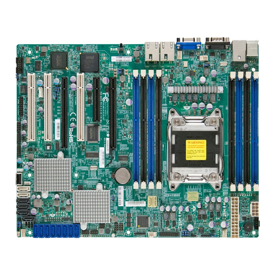
Chapter 1: Introduction Chapter 1 Introduction Overview Checklist Congratulations on purchasing your computer motherboard from an acknowledged leader in the industry. Supermicro boards are designed with the utmost attention to detail to provide you with the highest standards in quality and performance. Please check that the following items have all been included with your motherboard. - Page 16 X9SRH Motherboard Series User’s Manual X9SRH-7F Motherboard Series Image Note: All graphics shown in this manual were based upon the latest PCB Revision available at the time of publishing of the manual. The motherboard you've received may or may not look exactly the same as the graphics...
- Page 17 Chapter 1: Introduction X9SRH-7TF Motherboard Series Image Note: All graphics shown in this manual were based upon the latest PCB Revision available at the time of publishing of the manual. The motherboard you've received may or may not look exactly the same as the graphics shown in this manual.
- Page 18 X9SRH Motherboard Series User’s Manual Motherboard Layout UID_LED FAN4 FAN3 UID_SW JPL1/2: LAN USB0/1 JPUSB1 1-2 Enable 2-3 Disable IPMI_LAN LAN2 JLAN2 LAN1 JLAN1 JPL2 JVR1 JWOR1 DIMM_A2 DIMM_A1 DIMM_B1 DIMM_B2 JPB1 1-2 Enable JPL1 2-3 Disable JI2C2 CPU1 CLOSE 1st C361 Socket R LGA 2011...
- Page 19 Chapter 1: Introduction X9SRH Motherboard Series Quick Reference IPMI PS/2 MS FAN4 FAN3 USB0/1 PS/2 KB LAN2 LAN1 COM1 UID LED UID_LED UID SW FAN4 JI2C2 JI2C1 FAN3 UID_SW JPG1 JPL1/2: LAN JPUSB1 USB0/1 COM2 1-2 Enable 2-3 Disable JWOR1 IPMI_LAN LAN2 JLAN2...
- Page 20 JRK1 RAIDkey Header SPK1 Internal Speaker/Buzzer BATT Internal Battery SLOT1/SLOT2/SLOT4 PCI-32 Expansion Slot (SLOT4 is available on the X9SRH-7F Only) SLOT3 PCI-Express 3.0 x8 (in x16) Slot SLOT5 PCI-Express 2.0 x4 (in x8) Slot SLOT6 PCI-Express 3.0 x16 Slot DIMMA1~DIMMD2...
-
Page 21: Motherboard Features
One (1) PCI-Express 2.0 x4 in x8 Slot Integrated Graphics Matrox® G200eW (on BMC controller) Network Connections X9SRH-7F: Two (2) Gbit LAN Ports (1x Intel i350) X9SRH-7TF: Two (2) 10Gbit LAN Ports (1x Intel x540) I/O Devices SAS2/SATA Connections SAS2 Ports, 6Gb/s... - Page 22 X9SRH Motherboard Series User’s Manual Keyboard/Mouse One (1) each PS/2 KB and PS/2 Mouse port Serial (COM) Ports Two (2) Fast UART 16550 connections: one 9-pin RS-232 port (Backpanel COM1 port) and one header (COM2) Super I/O Winbond Super I/O NCT6776F BIOS 64 Mb SPI AMI BIOS SM Flash BIOS...
- Page 23 Chapter 1: Introduction X9SRH Motherboard Features Comparison Model SATA IPMI PCI-32 PCI-E PCI-E PCI-E (2.0/3.0) Slots x8 on x16 x4 on x8 X9SRH-7F 8 (6Gb/s) X9SRH-7TF 8 (6Gb/s) 10Gb...
-
Page 24: System Block Diagram
X9SRH Motherboard Series User’s Manual X9SRH Motherboard Series Block Diagram X9SRH #0-8 #0-7 #0-4 VR12 #0-6 #0-3 6 PHASE #0-5 #0-2 #0-1 Intel Processor 8 SNB CORE DDR-III MAX 130W #2A/B DMI2 #3A/B LAN#1/2 RJ45 1X "PCI-E X8 G3" SAS2308 PCI-E X8 G3 i350/x540 SLOT 6... -
Page 25: Chipset Overview
Chapter 1: Introduction Chipset Overview The Intel ® C602J is a single chip solution that is designed for dedicated servers and workstations. It supports high-speed SAS, SATA and advanced requirements for Intel ® Xeon platforms. Intel C602J Chipset Series Features •... -
Page 26: Special Features
X9SRH Motherboard Series User’s Manual Special Features Recovery from AC Power Loss Basic I/O System (BIOS) provides a setting for you to determine how the system will respond when AC power is lost and then restored to the system. You can choose for the system to remain powered off (in which case you must press the power switch to turn it back on), or for it to automatically return to a power-on state. -
Page 27: Acpi Features
Chapter 1: Introduction Windows OS environment or used with SuperDoctor II in Linux. SuperDoctor is used to notify the user of certain system events. For example, you can also configure SuperDoctor to provide you with warnings when the system temperature, CPU temperatures, voltages and fan speeds go beyond predefined thresholds. ACPI Features ACPI stands for Advanced Configuration and Power Interface. The ACPI specifica- tion defines a flexible and abstract hardware interface that provides a standard way to integrate power management features throughout a PC system, including its hardware, operating system and application software. -
Page 28: Super I/O
X9SRH Motherboard Series User’s Manual filter to shield the computer from noise. It is recommended that you also install a power surge protector to help avoid problems caused by power surges. Super I/O The Super I/O supports two high-speed, 16550 compatible serial communication ports (UARTs). Each UART includes a 16-byte send/receive FIFO, a programmable baud rate generator, complete modem control capability and a processor interrupt system. -
Page 29: Chapter 2 Installation
Chapter 2: Installation Chapter 2 Installation Static-Sensitive Devices Electrostatic-Discharge (ESD) can damage electronic com ponents. To avoid dam- aging your system board, it is important to handle it very carefully. The following measures are generally sufficient to protect your equipment from ESD. Precautions • Use a grounded wrist strap designed to prevent static discharge. • Touch a grounded metal object before removing the board from the antistatic bag. -
Page 30: Processor And Heatsink Installation
X9SRH Motherboard Series User’s Manual Processor and Heatsink Installation Warning: When handling the processor package, avoid placing direct pressure on the label area. Notes: Always connect the power cable last, and always remove it before adding, removing or changing any hardware components. Make sure that you in- stall the processor into the CPU socket before you install the CPU heatsink. -
Page 31: Opening The Lga2011 Socket
Chapter 2: Installation Opening the LGA2011 Socket The instructions on the following pages will show the 'regular' type socket. How- ever, they also apply to the 'narrow' type as well. The drawings are provided for illustration purposes only. 1. Before opening the LGA2011 socket, remove the black 'IMPORTANT!' plas- tic protective cap using your fingers and save it for future use. - Page 32 X9SRH Motherboard Series User’s Manual 1. Press the second load lever labeled 'Close 1st' to release the load plate which covers the CPU socket from its locking position. Press down on Load Lever 'Close 1st' Pull lever away from the socket 2.
-
Page 33: Installing The Lga2011 Processor
Chapter 2: Installation Installing the LGA2011 Processor 1. Use your thumb and index finger to hold the CPU on its edges. Align the CPU keys (semi-circle cutouts) against the socket keys. Socket Keys CPU Keys 2. Once it is aligned, carefully lower the CPU straight down into the socket. (Do not drop the CPU on the socket. Do not move the CPU horizontally or verti- cally.) Warning: You can only install the CPU inside the socket in one direction. - Page 34 X9SRH Motherboard Series User’s Manual 1. Do not rub the CPU against the surface or against any pins of the socket to avoid damaging the CPU or the socket.) 2. With the CPU inside the socket, inspect the four corners of the CPU to make sure that the CPU is properly installed.
-
Page 35: Installing A Passive Cpu Heatsink
Chapter 2: Installation Installing a Passive CPU Heatsink 1. Do not apply any thermal grease to the heatsink or the CPU die -- the re- quired amount has already been applied. 2. Place the heatsink on top of the CPU so that the four mounting holes are aligned with those on the Motherboard's and the Heatsink Bracket under- neath. -
Page 36: Removing The Heatsink
X9SRH Motherboard Series User’s Manual Removing the Heatsink Warning: We do not recommend that the CPU or the heatsink be removed. How- ever, if you do need to uninstall the heatsink, please follow the instructions below to uninstall the heatsink to prevent damage done to the CPU or the CPU socket. 1. -
Page 37: Installing Ddr3 Memory
Chapter 2: Installation Installing DDR3 Memory Note: Check the Supermicro website for recommended memory modules. CAUTION Exercise extreme care when installing or removing DIMM modules to prevent any possible damage. DIMM Installation UID_LED FAN4 FAN3 UID_SW JPL1/2: LAN USB0/1 JPUSB1 1-2 Enable 2-3 Disable IPMI_LAN... -
Page 38: Memory Support
X9SRH Motherboard Series User’s Manual Memory Support The X9SRH motherboard series supports up to 256GB of 1600/1066/1333/1600 MHz ECC/Non-ECC DDR3 DIMMs in eight (8) memory slots (UDIMM/RDIMM). Populating these DIMM modules with a pair of memory modules of the same type and same size will result in interleaved memory, which will improve memory performance. -
Page 39: Memory Population Guidelines
Chapter 2: Installation Memory Population Guidelines When installing memory modules, the DIMM slots should be populated in the follow- ing order: DIMMA1, DIMMB1, DIMMC1, DIMMD1 then DIMMA2, DIMMB2, DIMMC2, DIMMD2. • Always use DDR3 DIMM modules of the same size, type and speed. •... -
Page 40: Motherboard Installation
X9SRH Motherboard Series User’s Manual Motherboard Installation All motherboards have standard mounting holes to fit different types of chassis. Make sure that the locations of all the mounting holes for both motherboard and chassis match. Although a chassis may have both plastic and metal mounting fas- teners, metal ones are highly recommended because they ground the motherboard to the chassis. -
Page 41: Installing The Motherboard
Chapter 2: Installation Installing the Motherboard 1. Install the I/O shield into the chassis. 2. Locate the mounting holes on the motherboard. 3. Locate the matching mounting holes on the chassis. Align the mounting holes on the motherboard against the mounting holes on the chassis. 4. -
Page 42: Connectors/Io Ports
X9SRH Motherboard Series User’s Manual Connectors/IO Ports The I/O ports are color coded in conformance with the industry standards. See the figure below for the colors and locations of the various I/O ports. Motherboard I/O Backpanel UID_LED FAN4 FAN3 UID_SW JPL1/2: LAN USB0/1 JPUSB1 1-2 Enable 2-3 Disable IPMI_LAN LAN2 JLAN2 JLAN1 LAN1 JPL2... -
Page 43: Atx Ps/2 Keyboard/Mouse Ports
Chapter 2: Installation ATX PS/2 Keyboard/Mouse PS/2 Keyboard/Mouse Pin Ports Definitions PS2 Keyboard PS2 Mouse The ATX PS/2 keyboard and Pin# Definition Pin# Definition PS/2 mouse are located next to KBDAT_R MSDAT_R the Back Panel USB Ports 0/1 on No Connection No Connection the motherboard. -
Page 44: Universal Serial Bus (Usb)
X9SRH Motherboard Series User’s Manual Universal Serial Bus (USB) Back Panel USB Ports Pin Definitions Two Universal Serial Bus ports (USB Pin# Definition Pin# Definition 0/1) are located on the I/O back panel. In addition, six USB headers (USB USB_PN0 USB_PN1 2/3, USB 4/5, USB 6/7) are used to USB_PP0... -
Page 45: Ethernet Ports
USB 0/1 to provide a dedicated TRD3+ network connection for IPMI 2.0 on the TRD3- L1-COMMON motherboard. TRCT3 L1-GRE- LAN Connection Speeds: TRCT1 L2-YEL X9SRH-7F: 1Gb/sec TRD1+ L2-COMMON TRD1- L2-GRE- X9SRH-7TF: 10Gb/sec TRD4+ TRD4- TRCT4 (NC: No Connection) 1. LAN1 2. -
Page 46: Serial Ports
X9SRH Motherboard Series User’s Manual Serial Ports Serial Port Pin Definitions (COM1/COM2) A COM Port (COM1) is located on Pin # Definition Pin # Definition the I/O backpanel, and another Serial header (COM2) is located towards the rear of Slot 1 to provide front se- rial access. -
Page 47: Video Port
Chapter 2: Installation Video Port VGA Pin Definitions A Video (VGA) port is located next to Pin# Definition Pin# Definition the COM Port on the I/O backpanel. Ground This port is used to provide a connec- Green tion for video and graphics display. Blue MS1: SDA (DDC Data) Refer to the board layout below for... -
Page 48: Front Control Panel
X9SRH Motherboard Series User’s Manual Front Control Panel JF1 contains header pins for various buttons and indicators that are normally lo- cated on a control panel at the front of the chassis. These connectors are designed specifically for use with Supermicro server chassis. See the figure below for the descriptions of the various control panel buttons and LED indicators. -
Page 49: Front Control Panel Pin Definitions
Chapter 2: Installation Front Control Panel Pin Definitions Power LED Power LED Pin Definitions (JF1) The Power LED connection is located Pin# Definition on pins 15 and 16 of JF1. Refer to the +3.3V table on the right for pin definitions. Ground HDD LED HDD LED The HDD LED connection is located Pin Definitions (JF1) on pins 13 and 14 of JF1. -
Page 50: Nic1/Nic2 (Lan1/Lan2)
X9SRH Motherboard Series User’s Manual NIC1/NIC2 (LAN1/LAN2) LAN1/LAN2 LED Pin Definitions (JF1) The NIC (Network Interface Controller) Pin# Definition LED connection for LAN port 1 is located 9/11 on pins 11 and 12 of JF1, and the LED 10/12 LAN Active connection for LAN Port 2 is on Pins 9 and 10. -
Page 51: Nmi Button
Chapter 2: Installation NMI Button NMI Button Pin Definitions (JF1) The non-maskable interrupt button Pin# Definition header is located on pins 19 and 20 Control of JF1. Refer to the table on the right Ground for pin definitions. Reset Button The Reset Button connection is located Reset Button on pins 3 and 4 of JF1. -
Page 52: Connecting Cables & Optional Devices
X9SRH Motherboard Series User’s Manual Connecting Cables & Optional Devices This section provides brief descriptions and pin-out definitions for onboard headers and connectors. Be sure to use the correct cable for each header or connector. ATX Power 24-pin Connector ATX Main PWR (JPW1) & CPU PWR Pin Definitions (JPW1) Connectors (JPW2) Pin# Definition Pin # Definition The 24 - pin main power connector +3.3V... -
Page 53: Fan Headers (Fan1~4, Fana)
Chapter 2: Installation Fan Headers (FAN1~4, FANA) Fan Header Pin Definitions The X9SRH series has five fan headers (Fan Pin# Definition 1~Fan 4 and Fan A). These fans are 4-pin fan Ground (Black) headers. Pins 1-3 of these fan headers are +12V (Red) backward compatible with the traditional 3-pin Tachometer... -
Page 54: Speaker (Jd1)
X9SRH Motherboard Series User’s Manual Speaker (JD1) Speaker Connector Pin Definitions On the JD1 header, Pins 6~7 are used for Pin Setting Definition the internal speaker. Close Pins 6~7 with a Pins 6~7 Internal Speaker jumper or cap to use the onboard speaker. Pins 1~3 PWR LED If you wish to use an external speaker, at-... -
Page 55: Power Supply I
Chapter 2: Installation Power Supply I C (JPI2C1) PWR Supply I2C Pin Definitions The Power Supply I2C Connector, Pin# Definition located at JPI2C, monitors the status Clock of the power supply, fan and system Data temperature. See the table on the right PWR Fail for pin definitions. -
Page 56: T-Sgpio 1/2 & 6-Sgpio 1/2 Headers
X9SRH Motherboard Series User’s Manual T-SGPIO 1/2 & 6-SGPIO 1/2 Headers Serial_Link-SGPIO Pin Definitions Two T-SGPIO (Serial-Link General Pin# Definition Pin Definition Purpose Input/Output) headers are located next to the I-SATA Ports on the Ground DATA Out motherboard. Additionally, two 6-SGPIO Load Ground ports (for SAS2) are also located next Clock... -
Page 57: Unit Id Switch (Uid Sw)
Chapter 2: Installation Unit ID Switch (UID SW) UID Switch The rear UID switch, the rear UID LED and Pin# Definition front UID LED on JF1 are designed to work Button In together. When the user pushes the rear Ground UID switch, the blue backpanel UID LED Ground and front UID LED will turn on. -
Page 58: System Management Bus (Jipmb1 )
X9SRH Motherboard Series User’s Manual System Management Bus (JIPMB1 System Management A System Management Bus header for the Pin# Definition IPMI slot is located at IPMB. Connect the Clock appropriate cable here to use the IPMB I2C Ground connection on your system. Data No Connection Wake-On-Ring... -
Page 59: Raid Key Header (Jrk1 )
Chapter 2: Installation RAID Key Header (JRK1 RAID Key Header (Intel/LSI) The RAID key header supports an optional Pin# Definition RAID key (available separately). When RAID Key (Intel) plugged into this header, it will allow the user to enable the onboard SAS controller for software RAID 5 support (Intel or LSI). -
Page 60: Jumper Settings
X9SRH Motherboard Series User’s Manual Jumper Settings Explanation of Jumpers To modify the operation of the mother- board, jumpers can be used to choose between optional settings. Jumpers create shorts between two pins to change the function of the connector. Pin 1 is identified with a square solder pad on the printed circuit board. -
Page 61: Cmos Clear (Jbt1)
Chapter 2: Installation CMOS Clear (JBT1) JBT1 is used to clear CMOS. Instead of pins, this "jumper" consists of contact pads to prevent accidental clearing of CMOS. To clear CMOS, use a metal object such as a small screwdriver to touch both pads at the same time to short the connec- tion. -
Page 62: Vga Enable (Jpg1)
X9SRH Motherboard Series User’s Manual VGA Enable (JPG1) VGA Enable/Disable Jumper Settings (JPG1) JPG1 allows you to enable or disable the Both Jumpers Definition onboard VGA connector. The default posi- Pins 1-2 Enabled (Default) tion is on pins 1 and 2 to enable VGA. See Pins 2-3 Disabled the table on the right for jumper settings. -
Page 63: Usb Wake-Up (Jpusb1)
Chapter 2: Installation USB Wake-Up (JPUSB1) USB 0/1 Wake-up Enable Jumper Settings Use the jumper JPUSB1 to "wake-up" Pin# Definition your system by pressing a key on a USB Enabled (Default) keyboard or clicking the USB mouse con- Disabled nected to the backpanel USB Ports 0/1. JPUSB1 is used together with a USB Wake-Up feature in the BIOS. -
Page 64: Me Recovery (Jpme1)
X9SRH Motherboard Series User’s Manual ME Recovery (JPME1) ME Recovery (JPME1) When enabled, Intel ME Recovery (JPME1) Pin# Definition is used to update the ME (Management En- Normal (Default) gine) firmware. When disabled, the firmware ME Recovery is protected. It is optional for ME firmware update to exclude the protected area. ME Manufacturing Mode (JPME2) ME Manufacturing Mode (JPME2) -
Page 65: Onboard Indicators
Chapter 2: Installation Onboard Indicators Link LED Activity LED LAN Port LEDs The LAN ports are located on the I/O backpanel of the motherboard. Each Eth- Link LEDs (Green/Amber/Off) ernet LAN port has two LEDs. A blinking LED Color Definition Activity LED indicates there is data passing 100 Mbps through the port, while the Link LED may be Amber... -
Page 66: Rear Unit Id Led (Uid Led)
X9SRH Motherboard Series User’s Manual Rear Unit ID LED (UID LED) Rear UID LED LED Settings The rear Unit ID LED is located at UID Blue: Solid UID Toggled On LED on the backpanel. This LED is used in conjunction with the rear UID switch to provide easy identification of a system that might be in need of service. -
Page 67: Sata And Sas Connections
Chapter 2: Installation SATA and SAS Connections SATA/SAS Connections SATA/SAS Connectors Pin Definitions Six Serial ATA (SATA) connectors (I-SATA Pin# Signal 0~5) are located on the motherboard. I-SATA Ground 0/1 supports data transfer rates of up to SATA_TXP 6Gb/s (SATA 3.0), while I-SATA 2~5 supports SATA_TXN data transfer rates of up to 3Gb/s (SATA Ground... - Page 68 X9SRH Motherboard Series User’s Manual 2-40...
-
Page 69: Chapter 3 Troubleshooting
Chapter 3: Troubleshooting Chapter 3 Troubleshooting Troubleshooting Procedures Use the following procedures to troubleshoot your system. If you have followed all of the procedures below and still need assistance, refer to the ‘Technical Support Procedures’ and/or ‘Returning Merchandise for Service’ section(s) in this chapter. Always disconnect the AC power cable before adding, changing or installing any hardware components. -
Page 70: No Video
X9SRH Motherboard Series User’s Manual No Video 1. If the power is on, but you have no video--in this case, you will need to re- move all the add-on cards and cables first. 2. Use the speaker to determine if any beep codes exist. (Refer to Appendix A for details on beep codes.) 3. -
Page 71: Technical Support Procedures
Chapter 3: Troubleshooting Technical Support Procedures Before contacting Technical Support, please make sure that you have followed all the steps listed below. Also, Note that as a motherboard manufacturer, Supermicro does not sell directly to end users, so it is best to first check with your distributor or reseller for troubleshooting services. They should know of any possible problem(s) with the specific system configuration that was sold to you. -
Page 72: Frequently Asked Questions
X9SRH Motherboard Series User’s Manual Frequently Asked Questions Question: What type of memory does my motherboard support? Answer: Please see Section 2-3 for a comprehensive answer. Question: How do I update my BIOS? Answer: It is recommended that you do not upgrade your BIOS if you are not experiencing any problems with your system. Updated BIOS files are located on our website at http://www.supermicro.com/support/bios/. - Page 73 Chapter 3: Troubleshooting Answer: To solve this issue, disable the IPMI jumper. Another solution is to use a USB floppy drive instead of the onboard floppy drive. For the IPMI jumper location, please check Chapter 1. Question: What is the heatsink part number for my X9SRH Series motherboard? Answer: For the 1U passive heatsink, ask for SNK-P0046P (back plate is included). For the 2U active heatsink, use SNK-P0046A4.
-
Page 74: Battery Removal And Installation
X9SRH Motherboard Series User’s Manual Battery Removal and Installation Battery Battery Lock Battery Removal To remove the onboard battery, follow the steps below: 1. Power off your system and unplug your power Battery Holder cable. 2. Locate the onboard battery as shown below. 3. -
Page 75: Returning Merchandise For Service
Chapter 3: Troubleshooting Returning Merchandise for Service A receipt or copy of your invoice marked with the date of purchase is required before any warranty service will be rendered. You can obtain service by calling your vendor for a Returned Merchandise Authorization (RMA) number. For faster service, you may also obtain RMA authorizations online (http://www.supermicro. - Page 76 X9SRH Motherboard Series User’s Manual Notes...
-
Page 77: Chapter 4 Bios
Chapter 4: AMI BIOS Chapter 4 BIOS Introduction This chapter describes the AMI BIOS Setup Utility for the X9SRH Motherboard Series. The AMI ROM BIOS is stored in a Flash EEPROM and can be easily up- dated. This chapter describes the basic navigation of the AMI BIOS Setup Utility setup screens. -
Page 78: How To Start The Setup Utility
X9SRH Motherboard Series User’s Manual How To Change the Configuration Data The configuration data that determines the system parameters may be changed by entering the AMI BIOS Setup utility. This Setup utility can be accessed by pressing <Del> at the appropriate time during system boot. How to Start the Setup Utility Normally, the only visible Power-On Self-Test (POST) routine is the memory test. As the memory is being tested, press the <Delete> key to enter the main menu of the AMI BIOS Setup Utility. -
Page 79: Main Setup
Day MM/DD/YY format. The time is entered in HH:MM:SS format. (Note: The time is in the 24-hour format. For example, 5:30 P.M. appears as 17:30:00.) Supermicro X9SRH-7F/7TF Version: This item displays the version of the BIOS used in the system. -
Page 80: Advanced Setup Configurations
X9SRH Motherboard Series User’s Manual Advanced Setup Configurations Use the arrow keys to select Boot Setup and hit <Enter> to access the submenu items: BOOT Feature Quiet Boot This option allows the bootup screen options to be modified between POST mes- sages or the OEM logo. Select Disabled to display the POST messages. Select Enabled to display the OEM logo instead of the normal POST messages. The op- tions are Enabled and Disabled. -
Page 81: Retry Boot
Chapter 4: AMI BIOS 19 at boot and allow the drives that are attached to these host adaptors to function as bootable disks. If this item is set to Disabled, the ROM BIOS of the host adap- tors will not capture Interrupt 19, and the drives attached to these adaptors will not function as bootable devices. -
Page 82: Hyper Threading
X9SRH Motherboard Series User’s Manual Hyper Threading Set to Enabled to use the processor's Hyper Threading Technology feature. The options are Enabled and Disabled. Active Processor Cores Set to Enabled to use a processor's Second Core and beyond. (Please refer to Intel's web site for more information.) The options are All,1, 2, 4 and 6. -
Page 83: Intel ® Virtualization Technology (If Supported By The Cpu)
Chapter 4: AMI BIOS Intel Virtualization Technology (if supported by the CPU) ® Select Enabled to use the feature of Virtualization Technology to allow one plat- form to run multiple operating systems and applications in independent partitions, creating multiple "virtual" systems in one physical computer. The options are Enabled and Disabled. -
Page 84: Energy/Performance Bias
X9SRH Motherboard Series User’s Manual Energy/Performance Bias This feature sets the optimization balance between performance and power savings. The options are Performance, Balanced Performance, Balanced Energy and Energy Efficient. Long duration power limit This feature is the processor power consumption limit (in Watts) during a long duration time window. -
Page 85: Mmcfg Base
Chapter 4: AMI BIOS MMCFG BASE This feature allows the user to specify a base address computation (for ACPI base address reporting) for regions that do not start at bus 0. The options are 0x80000000, 0xA0000000, and 0xC0000000. IIO 1 PCIe Port Bifurcation Control CPU1 Slot 3 PCI-E 3.0 x8 (in x16) Link Speed This feature enables the user to select the target link speed for this slot. -
Page 86: Ddr Speed
X9SRH Motherboard Series User’s Manual processors The options are DRAM RAPL MODE0 , DRAM RAPL MODE1, and Disabled. DDR Speed Use this option to force the system memory to run at a different frequency than the default frequency. The available options are Auto, Force DDR- 800, Force DDR-1066, Force DDR-1333, Force DDR3-1600 and Force SPD. -
Page 87: Thermal Throttling
Chapter 4: AMI BIOS Thermal Throttling This feature selects from the different throttling methods. The options are Disabled and CLTT (Closed Loop Thermal Throttling). South Bridge Configuration This item displays the current South Bridge Revision. All USB Devices This feature enables all USB ports/devices. The options are Enabled and Disabled. -
Page 88: Sata Mode
X9SRH Motherboard Series User’s Manual SATA Mode This item selects the mode for the installed drives. The options are Disabled, IDE Mode, AHCI Mode and RAID Mode. The following are displayed depending on your selection: IDE Mode The following items are displayed when IDE Mode is selected: Serial-ATA Controller 0~1 This feature is used to activate/deactivate the SATA controller, and sets the compatibility mode. -
Page 89: Pcie/Pci/Pnp Configuration
Chapter 4: AMI BIOS PCIe/PCI/PnP Configuration This feature allows the user to set the PCI/PnP configurations for the following items: Launch Storage OpROM Policy In case of multiple Option ROMs (Legacy and UEFI-compatible), this feature speci- fies what ROM to launch. The options are Legacy Only and UEFI Only. PCI Latency Timer This feature sets the latency Timer of each PCI device installed on a PCI bus. Se- lect 64 to set the PCI latency to 64 PCI clock cycles. -
Page 90: Slot1 Pci 33Mhz Oprom
Slot1 PCI 33MHZ OPROM Slot2 PCI 33MHZ OPROM CPU1 Slot3 PCI-E 3.0 x8 (in x16) OPROM Slot4 PCI 33MHz OPROM (X9SRH-7F only) PCH Slot5 PCI-E 2.0 x4 OPROM CPU1 Slot6 PCI-E 3.0 x16 OPROM Use this feature to enable or disable PCI-E slot Option ROMs. The options are Disabled and Enabled. -
Page 91: Serial Port Console Redirection
Chapter 4: AMI BIOS Auto, IO=3F8h; IRQ=4; IO=3F8h; IRQ=3, 4, 5, 6, 7, 9, 10, 11, 12; IO=2F8h; IRQ=3, 4, 5, 6, 7, 9, 10, 11, 12; IO=3E8h; IRQ=3, 4, 5, 6, 7, 9, 10, 11, 12; IO=2E8h; IRQ=3, 4, 5, 6, 7, 9, 10, 11, 12; The options for Serial Port 2 are: Auto, IO=2F8h; IRQ=3; IO=3F8h; IRQ=3, 4, 5, 6, 7, 9, 10, 11, 12; IO=2F8h; IRQ=3, 4, 5, 6, 7, 9, 10, 11, 12; IO=3E8h; IRQ=3, 4, 5, 6, 7, 9, 10, 11, 12; IO=2E8h; IRQ=3, 4, 5, 6, 7, 9, 10, 11, 12; Serial Port Console Redirection COM1, COM2, or SOL Console Redirection Use this feature to enable console redirection for COM1, COM2, and SOL ports. The options are Enabled and Disabled. -
Page 92: Acpi Settings
X9SRH Motherboard Series User’s Manual Resolution 100x31: Disabled or Enabled Legacy OS Redirection Resolution: 80x24 or 80x25 PuTTY Keypad: VT100, Linux, XTerm86, SCO, ESCN, VT400 Redirection After BIOS POST: Always Enable, Bootloader Serial Port for Out-of-Band Management / Windows Emergency Management Services (EMS) Use this feature to enable console redirection. -
Page 93: Trusted Computing
Chapter 4: AMI BIOS synchronizing multimedia streams, providing smooth playback and reducing the de- pendency on other timestamp calculation devices, such as an x86 RDTSC Instruc- tion embedded in the CPU. The High Performance Event Timer is used to replace the 8254 Programmable Interval Timer. -
Page 94: Me Subsystem
X9SRH Motherboard Series User’s Manual ME Subsystem This item displays the ME Subsystem information. iSCSI Configuration When sharing the iSCSI devices on this machine (iSCSI target), this section is used to enter the worldwide unique name of an iSCSI initiator. An iSCSI initiator application must be configured on the machine that will access the iSCSI drives in this machine. -
Page 95: Delete Attempts
Chapter 4: AMI BIOS Boot LUN - This is the target's LU number in Hexadecimal format. Authentication Type - Select CHAP or None. If CHAP is selected above: CHAP Type - Select One Way or Mutual. CHAP Name - Assign a name for this authentication. CHAP Secret - Assign a secret word that is also defined in the target iSCSI device. -
Page 96: Event Logs
X9SRH Motherboard Series User’s Manual Event Logs Change SmBIOS Event Log Settings Smbios Event Log Change this item to enable or disable all features of the Smbios Event Logging during boot. The options are Enabled and Disabled. Runtime Error Logging Support Change this item to enable or disable runtime error logging. -
Page 97: Log System Boot Event
Chapter 4: AMI BIOS Log System Boot Event This option toggles the System Boot Event logging to enabled or disabled. The options are Disabled and Enabled. MECI The Multiple Event Count Increment (MECI) counter counts the number of occurences a duplicate event must happen before the MECI counter is incre- mented. -
Page 98: Ipmi
X9SRH Motherboard Series User’s Manual IPMI Intelligent Platform Management Interface (IPMI) is a set of common interfaces that IT administrators can use to monitor system health and to manage the system as a whole. For more information on the IPMI specifications, please visit Intel's website at www.intel.com. System Event Log This feature is used to change the Sytem Event Log (SEL) configuration. -
Page 99: Configuration Address Source
Chapter 4: AMI BIOS Configuration Address Source This feature selects whether the IP address, Subnet Mask and Gateway Address are automatically assigned by the network's DHCP server (Dynamic Host and Con- figuration Protocol) "Dynamic" or manually entered by the user "Static". If Static is selected, the IP Address, Subnet Mask and Gateway Address must be manually entered below. -
Page 100: Boot Settings
X9SRH Motherboard Series User’s Manual Boot Settings Use this feature to configure Boot Settings: Set Boot Priority 1st Boot Device, 2nd Boot Device, 3rd Boot Device, etc. Use these items to specify the sequence of boot device priority. Add Boot Option This feature appears if the BIOS detects UEFI-capable devices. This allows the user to define a boot device from which the systems boots during startup. -
Page 101: Security Settings
Chapter 4: AMI BIOS Security Settings Password Check Use this feature to determine when a password entry is required. Select Setup to require the password only when entering setup. Select Always to require the pass- word when entering setup and on each boot. The options are Setup and Always. Administrator Password Use this feature to set the Administrator Password which is required to enter the BIOS setup utility. -
Page 102: Save & Exit
X9SRH Motherboard Series User’s Manual Save & Exit Select the Exit tab from the BIOS Setup Utility screen to enter the Exit BIOS Setup screen. Discard Changes and Exit Select this option to quit the BIOS Setup without making any permanent changes to the system configuration, and reboot the computer. Select Discard Changes and Exit from the Exit menu and press <Enter>. -
Page 103: Restore Optimized Defaults
Chapter 4: AMI BIOS Restore Optimized Defaults To set this feature, select Restore Defaults from the Exit menu and press <Enter>. These are factory settings designed for maximum system stability, but not for maximum performance. Save As User Defaults To set this feature, select Save as User Defaults from the Exit menu and press <En- ter>. This enables the user to save any changes to the BIOS setup for future use. Restore User Defaults To set this feature, select Restore User Defaults from the Exit menu and press <En- ter>. Use this feature to retrieve user-defined settings that were saved previously. - Page 104 X9SRH Motherboard Series User’s Manual Notes 4-28...
-
Page 105: Appendix A Bios Error Beep Codes
Appendix A: POST Error Beep Codes Appendix A BIOS Error Beep Codes During the POST (Power-On Self-Test) routines, which are performed each time the system is powered on, errors may occur. Non-fatal errors are those which, in most cases, allow the system to continue with bootup. - Page 106 X9SRH Motherboard Series User’s Manual Notes...
-
Page 107: Appendix B Software Installation Instructions
Appendix B: Software Installation Instructions Appendix B Software Installation Instructions B-1 Installing Drivers After you've installed the Windows Operating System, a screen as shown below will appear. You are ready to install software programs and drivers that have not yet been installed. To install these software programs and drivers, click the icons to the right of these items. -
Page 108: Configuring Superdoctor ® Iii
X9SRH Motherboard Series User’s Manual B-2 Configuring SuperDoctor ® The SuperDoctor III program is a Web-based management tool that supports remote management capability. It includes Remote and Local Management tools. The local management tool is called the SD III Client. The SuperDoctor III program included on the CDROM that came with your motherboard allows you to monitor the environment and operations of your system. - Page 109 Appendix B: Software Installation Instructions SuperDoctor® III Interface Display Screen-II (Remote Control) Note: The SuperDoctor III software and manual may be downloaded from our Website at: http://www.supermicro.com/products/accessories/software/SuperDoctorIII.cfm. For Linux, we still recommend that you use SuperDoctor II, this version is also available for download at the link above.
- Page 110 X9SRH Motherboard Series User’s Manual Notes...
-
Page 111: Appendix C Uefi Bios Recovery Instructions
UEFI BIOS Recovery Appendix C UEFI BIOS Recovery Instructions Warning! Do not upgrade the BIOS unless your system has a BIOS-related issue. Flashing the wrong BIOS can cause irreparable damage to the system. In no event shall Supermicro be liable for direct, indirect, special, incidental, or consequential damages arising from a BIOS update. - Page 112 X9SRH Motherboard Series User’s Manual To perform UEFI BIOS recovery using a USB-attached device, follow the instruc- tions below. 1. Using a different machine, copy the "Super.ROM" binary image file into the disc Root "\" Directory of a USB device or a writeable CD/DVD. Note: If you cannot locate the "Super.ROM" file in your driver disk, visit our website at www.supermicro.com to download the BIOS image into a USB flash device and rename it to "Super.ROM" for BIOS recovery use.
- Page 113 UEFI BIOS Recovery Aptio Setup Utility - Copyright (C) 2011 American Megatrends, Inc. Recovery WARNING! System rmware is being updated. Keyboard is locked. DO NOT TURN THE POWER OFF!!! Once rmware update is completed press any key to reboot the system Flash update progress Select Screen Select Item...
- Page 114 X9SRH Motherboard Series User’s Manual 8. When a DOS prompt appears, type AMI.BAT BIOSname.### at the prompt. Note: Do not interrupt this process until BIOS flashing is completed. 9. After seeing the message that BIOS update is completed, unplug the AC power cable to clear CMOS, and then plug in the AC power cable to power on the system.
- Page 115 (Disclaimer Continued) The products sold by Supermicro are not intended for and will not be used in life support systems, medical equipment, nuclear facilities or systems, aircraft, aircraft devices, aircraft/emergency com- munication devices or other critical systems whose failure to perform be reasonably expected to result in significant injury or loss of life or catastrophic property damage. Accordingly, Supermicro disclaims any and all liability, and should buyer use or sell such products for use in such ultra-hazardous ap- plications, it does so entirely at its own risk.
Need help?
Do you have a question about the X9SRH-7F and is the answer not in the manual?
Questions and answers