Table of Contents
Advertisement
Quick Links
Advertisement
Table of Contents

Related Manuals for Supero Supero X9SAE


Summary of Contents for Supero Supero X9SAE
- Page 1 X9SAE X9SAE-V USER’S MANUAL Revision 1.0...
- Page 2 This product, including software and docu- mentation, is the property of Supermicro and/or its licensors, and is supplied only under a license. Any use or reproduction of this product is not allowed, except as expressly permitted by the terms of said license.
-
Page 3: About This Motherboard
PC gaming platform. Please refer to our website (http://www.supermicro.com/products/) for processor and memory support updates. This product is intended to be installed and serviced by professional technicians. -
Page 4: Conventions Used In The Manual
X9SAE Motherboard Series User’s Manual Conventions Used in the Manual: Special attention should be given to the following symbols for proper installation and to prevent damage done to the components or injury to yourself: Danger/Caution: Instructions to be strictly followed to prevent catastrophic system failure or to avoid bodily injury Warning: Critical information to prevent damage to the components or data loss. -
Page 5: Contacting Supermicro
Super Micro Computer, Inc. 980 Rock Ave. San Jose, CA 95131 U.S.A. Tel: +1 (408) 503-8000 Fax: +1 (408) 503-8008 Email: marketing@supermicro.com (General Information) support@supermicro.com (Technical Support) Web Site: www.supermicro.com Europe Address: Super Micro Computer B.V. Het Sterrenbeeld 28, 5215 ML... -
Page 6: Table Of Contents
X9SAE Motherboard Series User’s Manual Table of Contents Preface About This Motherboard ....................iii Manual Organization ..................... iii Conventions Used in the Manual: .................iv Contacting Supermicro ....................v Chapter 1 Introduction Overview ......................1-1 Checklist ......................1-1 Motherboard Features ..................1-7 Chipset Overview .................. - Page 7 Table of Contents Memory Population Guidelines ............... 2-9 Motherboard Installation .................2-11 Tools Needed ....................2-11 Location of Mounting Holes ................2-11 Installing the Motherboard ................2-12 Connectors/IO Ports ..................2-13 Backplane I/O Panel ..................2-13 ATX PS/2 Keyboard/Mouse Ports ............2-14 Universal Serial Bus (USB) ..............2-15 Ethernet Ports ..................
- Page 8 X9SAE Motherboard Series User’s Manual LAN Port Enable/Disable (JPL1/JPL2) ............. 2-30 CMOS Clear (JBT1) ................. 2-31 PCI Slot SMB Enable (I C1/I C2) ............. 2-31 ME Manufacturing Mode (JPME2) ............2-32 ME Recovery Mode (JPME1)..............2-32 Audio Enable (JPAC1)................2-33 Watch Dog Timer Reset (JWD1) ..............
- Page 9 Table of Contents Supermicro X9SAE ..................4-3 Version ......................4-3 Build Date ....................4-3 Processor ....................4-3 Speed ......................4-3 Physical Count ................... 4-3 Logical Count ..................... 4-3 System Memory ..................4-3 Size......................4-3 4-3 Advanced Setup Configurations..............4-4 Boot Feature ....................4-4 Quiet Boot ....................
- Page 10 X9SAE Motherboard Series User’s Manual Chipset Configuration ..................4-8 Memory Frequency ..................4-8 VT-d ......................4-8 Active State Power Management ............... 4-8 PCIE Maximum Read Request ..............4-8 PCI Express Port ..................4-8 PCI Express Port - Gen X ................4-9 De-emphasis Control ..................
- Page 11 Table of Contents Fan Speed Control Mode ................. 4-15 CPU Temperature ..................4-15 System Temperature / Peripheral Temperature / PCH Temperature ..4-15 Fan 1 ~ Fan 4, Fan A Reading ..............4-16 VCORE, 12V, VDIMM, 5VCC, VTT, AVCC, 3.3VCC, VSB, VBAT ... 4-16 ...
- Page 12 X9SAE Motherboard Series User’s Manual View SmBIOS Event Log ................. 4-20 Boot Settings ....................4-21 Setup Prompt Timeout ................4-21 Retry Boot Devices .................. 4-21 Boot Option Filter ..................4-21 Boot Option #1, #2, #3, ................4-21 Network Device BBS Priorities, CD/DVD ROM Drive BBS Priorities, Hard Drive BBS Priorities, ................
-
Page 13: Introduction
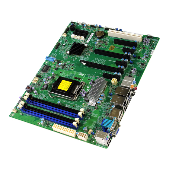
Checklist Congratulations on purchasing your computer motherboard from an acknowledged leader in the industry. Supermicro boards are designed with the utmost attention to detail to provide you with the highest standards in quality and performance. Please check that the following items have all been included with your motherboard. - Page 14 X9SAE Motherboard Series User’s Manual X9SAE Motherboard Image Note: All graphics shown in this manual were based upon the latest PCB Revision available at the time of publishing of the manual. The motherboard you've received may or may not look exactly the same as the graphics shown in this manual.
- Page 15 Chapter 1: Introduction X9SAE Motherboard Layout X9SAE REV:1.01 HDMI_ VGA/ HDMI1/2 COM1 JUSBLAN2 JPCIE5 JPCIE8 JPCIE9 JPL1 JPW2 JPW3 JPME2 BIOS LICENSE JPME1 JTPM1 DESIGNED IN USA JPUSB2 C3102 USB4/5 I-SATA4 I-SATA2 I-SATA0 I-SATA5 I-SATA3 I-SATA1 JSD1 JBT1 USB11/12 BUZZER R616 JD1: PWR RST...
- Page 16 X9SAE Motherboard Series User’s Manual X9SAE Quick Reference JAUDIO1 LAN2 LAN1 HDMI1 COM1 KB/MS S/PDIF IN USB2/3 USB10/13 HDMI2 USB8/9 S/PDIF OUT JPL1 JPAC1 JI2C2 JI2C1 JPL2 JPW3 X9SAE REV:1.01 AUDIO FP HDMI_ VGA/ HDMI1/2 COM1 JUSBLAN2 JPUSB1 JPCIE5 JPCIE8 JPCIE9 JPL1 JPW2...
-
Page 17: Back Panel
Chapter 1: Introduction Back Panel HD Audio Backplane I/O Panel A. USB 2.0 Port 9 G. USB 2.0 Port 13 M. SPDIF Out B. USB 2.0 Port 8 H. USB 2.0 Port 10 N. Surround Out C. Keyboard/Mouse I. Gb LAN Port 1 O. - Page 18 X9SAE Motherboard Series User’s Manual X9SAE Motherboard Series Headers/Connectors Connector Description AUDIO FP Front Panel Audio Header JAUDIO High-Definition Audio Connectors (on the I/O back panel) BAT1, SPK1 Onboard Battery, Internal Speaker/Buzzer COM1, COM2 COM1 Port (Back Panel), COM2 Serial Port Header FAN1~FAN4, FANA System/CPU Fan Headers (FAN1: CPU Fan, FANA: I/O Cards) Speaker/buzzer (Pins 1-2: Buzzer, Pins 1~4: External Speaker)
-
Page 19: Motherboard Features
Chapter 1: Introduction Motherboard Features Intel® Xeon® E3-1200 v2 series, Xeon E3-1200 series, Pentium®, and Celeron® processor in an LGA 1155 socket Memory Four (4) slots support up to 32 GB of unbuffered, ECC DDR3 UDIMM memory (1600/1333/1066 MHz) Supports dual-channel memory bus DIMM sizes UDIMM 2 GB, 4GB, and 8GB... - Page 20 X9SAE Motherboard Series User’s Manual Audio Five (5) Female Mini Jacks for High Definition Audio on the Back Panel Front Panel Audio Header One (1) S/PDIF Optical Out on the back panel S/PDIF In and S/PDIF Out Headers Video One VGA (D-Sub), two (2) HDMI ports on the back panel nVidia®...
-
Page 21: Block Diagram
Chapter 1: Introduction X9SAE Motherboard Series Block Diagram BLOCK DIAGRAM RoHS 6/6 PCIe3.0_x8 SVID PCIe x16 SLOT #6 VRM 12 8.0GT/s X9SAE-V Only INTEL CPU PCIe3.0_x8 DDR3 (CHA) DIMM1A (Blue) PCIe x16 SLOT #4 8.0GT/s DIMM1B (Socket-H2) 1600/1333MHz DDR3 (CHB) PCIe2.0_x4 DIMM2A (Blue) PCIe x4 SLOT #7... -
Page 22: Chipset Overview
X9SAE Motherboard Series User’s Manual Chipset Overview The X9SAE Motherboard Series supports a single Intel® Xeon® E3-1200 v2 series, Xeon E3-1200 series, Pentium®, and Celeron® processor in an LGA 1155 socket. Leveraging the features of the Intel C216 chipset, the X9SAE motherboard pro- vides substantial enhancement to system performance high performance gaming platforms and entry-level workstations. -
Page 23: Special Features
Chapter 1: Introduction Special Features Recovery from AC Power Loss Basic I/O System (BIOS) provides a setting for you to determine how the system will respond when AC power is lost and then restored to the system. You can choose for the system to remain powered off, (in which case you must press the power switch to turn it back on), or for it to automatically return to a power-on state. -
Page 24: System Resource Alert
X9SAE Motherboard Series User’s Manual System Resource Alert This feature is available when the system is used with Supero Doctor III in the Windows OS environment or used with Supero Doctor II in Linux. Supero Doctor is used to notify the user of certain system events. For example, you can also configure Supero Doctor to provide you with warnings when the system temperature, CPU temperatures, voltages and fan speeds go beyond predefined thresholds. -
Page 25: Super I/O
Chapter 1: Introduction nectors. Be sure to connect these connectors to the 24-pin (JPW1) and the 8-pin (JPW2) power connectors on the motherboard. Failure in doing so will void the manufacturer warranty on your power supply and motherboard. 2. To provide adequate power to Disk on Module SATA devices, please connect them to the SATA DOM PWR connector (JWF1). - Page 26 X9SAE Motherboard Series User’s Manual Notes 1-14...
-
Page 27: Installation
Chapter 2: Installation Chapter 2 Installation Static-Sensitive Devices Electrostatic-Discharge (ESD) can damage electronic com ponents. To avoid dam- aging your system board, it is important to handle it very carefully. The following measures are generally sufficient to protect your equipment from ESD. Precautions •... -
Page 28: Processor And Heatsink Installation
CPU socket cap is in place and none of the socket pins are bent; otherwise, contact your retailer immediately. Refer to the Supermicro website for updates on CPU support. Installing the LGA1155 Processor 1. Press the load lever to release the load plate, which covers the CPU socket, from its locking position. - Page 29 Chapter 2: Installation 2. Gently lift the load lever to open the load plate. Remove the plastic cap. 3. Use your thumb and your index finger to hold the CPU at the North center edge and the South center edge of the CPU. North Center Edge South Center Edge 4.
- Page 30 X9SAE Motherboard Series User’s Manual 5. Do not rub the CPU against the surface or against any pins of the socket to avoid damaging the CPU or the socket.) 6. With the CPU inside the socket, inspect the four corners of the CPU to make sure that the CPU is properly installed.
-
Page 31: Installing An Active Cpu Heatsink With Fan
6. If necessary, rearrange the wires to make sure that the wires are not pinched between the heatsink and the CPU. Also make sure to keep clearance between the fan wires Recommended Supermicro heatsink: and the fins of the heatsink. SNK-P0046A4 active heatsink... - Page 32 X9SAE Motherboard Series User’s Manual 7. Align the four heatsink fasten- ers with the mounting holes on the motherboard. Gently push the pairs of diagonal fasteners (#1 & #2, and #3 & #4) into the mounting holes until you hear a click. Also, make sure to orient each fastener so that the narrow end of the groove is pointing...
-
Page 33: Removing The Heatsink
Chapter 2: Installation Removing the Heatsink Caution: We do not recommend that the CPU or the heatsink be removed. However, if you do need to remove the heatsink, please follow the instructions be- low to remove the heatsink and to prevent damage done to the CPU or other components. -
Page 34: Installing Ddr3 Memory
X9SAE Motherboard Series User’s Manual Installing DDR3 Memory Note: Check the Supermicro website for recommended memory mod- ules. CAUTION Exercise extreme care when installing or removing DIMM modules to prevent any possible damage. X9SAE REV:1.01 DIMM Installation HDMI_ HDMI1/2 VGA/... -
Page 35: Memory Support
Chapter 2: Installation Memory Support The X9SAE Motherboard Series supports up to 32GB of Unbuffered (UDIMM) DDR3 ECC/Non-ECC 1600/1333/1066 MHz in 4 memory slots. Populating these DIMM modules with a pair of memory modules of the same type and same size will result in interleaved memory, which will improve memory performance. - Page 36 X9SAE Motherboard Series User’s Manual Possible System Memory Allocation & Availability Area Reserved for the chipset 2 MB 3.99 I/O APIC (4 Kbytes) 4 KB 3.99 PCI Enumeration Area 1 256 MB 3.76 PCI Express (256 MB) 256 MB 3.51 PCI Enumeration Area 2 (if needed) -Aligned on 256-MB 512 MB 3.01...
-
Page 37: Motherboard Installation
Chapter 2: Installation Motherboard Installation All motherboards have standard mounting holes to fit different types of chassis. Make sure that the locations of all the mounting holes for both motherboard and chassis match. Although a chassis may have both plastic and metal mounting fas- teners, metal ones are highly recommended because they ground the motherboard to the chassis. -
Page 38: Installing The Motherboard
X9SAE Motherboard Series User’s Manual Installing the Motherboard 1. Install the I/O shield into the back of the chassis. 2. Locate the mounting holes on the motherboard. (See the previous page.) 3. Locate the matching mounting holes on the chassis. Align the mounting holes on the motherboard against the mounting holes on the chassis. -
Page 39: Connectors/Io Ports
Chapter 2: Installation Connectors/IO Ports The I/O ports are color coded in conformance with the PC 99 specification. See the figure below for the colors and locations of the various I/O ports. Backplane I/O Panel X9SAE REV:1.01 HDMI_ VGA/ HDMI1/2 COM1 JUSBLAN2 JPCIE8... -
Page 40: Atx Ps/2 Keyboard/Mouse Ports
X9SAE Motherboard Series User’s Manual ATX PS/2 Keyboard/Mouse PS/2 Keyboard/Mouse Pin Ports Definitions PS2 Keyboard PS2 Mouse The ATX PS/2 keyboard and Pin# Definition Pin# Definition PS/2 mouse are located next to KB Data Mouse Data the Back Panel USB Ports 8/9 on No Connection No Connection the motherboard. -
Page 41: Universal Serial Bus (Usb)
Chapter 2: Installation Universal Serial Bus (USB) Four Universal Serial Bus 2.0 ports #2, #3, #8, #9, #10, #13, USB 3.0 #3, #4, are located on the I/O back panel. USB 2.0 headers #4/5, #11/12, #0/1 and USB 3.0 header #1/2 are used to provide front chassis access using USB cables (not included). -
Page 42: Ethernet Ports
X9SAE Motherboard Series User’s Manual Ethernet Ports LAN Ports Pin Definition Two Gigabit Ethernet ports (LAN1/ Pin# Definition LAN2) are located next to the HD Au- P2V5SB SGND dio Connector on the I/O Backpanel to TD0+ Act LED provide network connections. These TD0- P3V3SB ports accept RJ45 type cables. -
Page 43: Front Accessible Audio Header
Chapter 2: Installation Front Accessible Audio Header 10-in Audio Pin Definitions A 10-pin Audio header is also Pin# Signal located on the motherboard. This Microphone_Left header allows you to use the on- Audio_Ground board sound for audio playback. Microphone_Right Connect an audio cable to the au- Audio_Detect dio header to use this feature. -
Page 44: Hdmi Ports
X9SAE Motherboard Series User’s Manual HDMI Ports Two HDMI (High-Definition Multimedia Inter- face) Ports are located next to the VGA port on the I/O backpanel. This connector is used to display both high definition video and digi- tal sound through an HDMI-capable display, using a single HDMI cable (not included). -
Page 45: Front Control Panel
These connectors are designed spe- cifically for use with Supermicro chassis. See the figure below for the descriptions of the front control panel buttons and LED indicators. Refer to the following section for descriptions and pin definitions. -
Page 46: Front Control Panel Pin Definitions
X9SAE Motherboard Series User’s Manual Front Control Panel Pin Definitions Power LED Power LED Pin Definitions (JF1) The Power LED connection is located Pin# Definition on pins 15 and 16 of JF1. Refer to the table on the right for pin definitions. Ground HDD LED The HDD LED connection is located... -
Page 47: Nic1/Nic2 (Lan1/Lan2)
Chapter 2: Installation NIC1/NIC2 (LAN1/LAN2) LAN1/LAN2 LED Pin Definitions (JF1) The NIC (Network Interface Controller) Pin# Definition LED connection for LAN port 1 is located 9/11 on pins 11 and 12 of JF1, and the LED 10/12 Ground connection for LAN Port 2 is on Pins 9 and 10. -
Page 48: Reset Button
X9SAE Motherboard Series User’s Manual Reset Button The Reset Button connection is located Reset Button Pin Definitions (JF1) on pins 3 and 4 of JF1. Attach it to a Pin# Definition hardware reset switch on the computer Reset case to reset the system. Refer to the Ground table on the right for pin definitions. -
Page 49: Connecting Cables
Chapter 2: Installation Connecting Cables This section provides brief descriptions and pin-out definitions for onboard headers and connectors. Be sure to use the correct cable for each header or connector. ATX Power 24-pin Connector ATX Main PWR & CPU PWR Pin Definitions (JPW1) Connectors (JPW1 &... -
Page 50: Fan Headers (Fan 1 ~ Fan 4, Fan A)
X9SAE Motherboard Series User’s Manual Fan Headers (FAN 1 ~ FAN 4, FAN A) Fan Header Pin Definitions The X9SAE Motherboard Series has five fan Pin# Definition headers (Fan 1~Fan 4 & Fan A). These fans Ground (Black) are 4-pin fan headers. Although pins 1-3 of the 2.5A/+12V fan headers are backward compatible with the (Red) -
Page 51: Internal Buzzer (Spk1)
Chapter 2: Installation Internal Buzzer (SPK1) Internal Buzzer Pin Definition The Internal Buzzer (SPK1) can be Pin# Definitions used to provide audible indications for Pin 1 Pos. (+) Beep In various beep codes. See the table on Pin 2 Neg. (-) Alarm the right for pin definitions. -
Page 52: Onboard Power Led (Jled)
X9SAE Motherboard Series User’s Manual Onboard Power LED (JLED) Onboard PWR LED Pin Definitions An onboard Power LED header is lo- Pin# Definition cated at JLED. This Power LED header is connected to the Front Control Panel No Connection located at JF1 to indicate the status of Connection to PWR system power. -
Page 53: Dom Pwr Connector (Jsd1)
Chapter 2: Installation DOM PWR Connector (JSD1) DOM PWR Pin Definitions The Disk-On-Module (DOM) power Pin# Definition connector, located at JSD1, provides 5V (Gen1/Gen) power to a solid state Ground DOM storage device connected to one Ground of the SATA ports. See the table on the right for pin definitions. -
Page 54: Spdif In / Spdif Out (Jspdif_In/Jspdif_Out)
X9SAE Motherboard Series User’s Manual SPDIF IN / SPDIF OUT (JSPDIF_IN/ SPDIF_Out SPDIF_In JSPDIF_OUT) Pin Definitions Pin Definitions The SP/DIF In (JSPDIF_IN) and SP/ Pin# Definition Pin# Definition DIF Out (JSPDIF_OUT) are used S/PDIF_Out S/PDIF_In for digital audio. You will also need Ground Ground the appropriate cables to use these... -
Page 55: T-Sgpio Headers (T-Sgpio1/2)
Chapter 2: Installation T-SGPIO Headers (T-SGPIO1/2) Serial_Link-SGPIO Pin Definitions The T-SGPIO1 and T-SGPIO2 (Serial- Pin# Definition Definition Link General Purpose Input/Output) headers are located near the SATA Ground DATA Out connectors on the motherboard. These Load Ground headers are used to communicate with Clock the enclosure management chip in the system. -
Page 56: Jumper Settings
X9SAE Motherboard Series User’s Manual Jumper Settings Explanation of Jumpers To modify the operation of the mother- board, jumpers can be used to choose between optional settings. Jumpers create shorts between two pins to change the function of the connector. Pin 1 is identified with a square solder pad on the printed circuit board. -
Page 57: Cmos Clear (Jbt1)
Chapter 2: Installation CMOS Clear (JBT1) JBT1 is used to clear the saved system setup stored in the CMOS chip. To clear the contents of the CMOS, completely shut down the system, remove the AC power cord and then short JBT1 with a jumper. Remove the jumper before powering on the system again. -
Page 58: Me Manufacturing Mode (Jpme2)
X9SAE Motherboard Series User’s Manual ME Manufacturing Mode (JPME2) JPME2 Jumper Settings Close pins 2-3 of JPME2 to enable ME Manu- Both Jumpers Definition facturing Mode. See the table on the right Pins 1-2 Disabled for jumper settings. Note: ME Manufactur- Pins 2-3 Enabled ing Mode may be enabled without changing... -
Page 59: Audio Enable (Jpac1)
Chapter 2: Installation Audio Enable (JPAC1) Audio Enable/Disable Jumper Settings JPAC1 allows you to enable or disable Both Jumpers Definition the onboard audio support. The default Pins 1-2 Enabled position is on pins 1 and 2 to enable on- Pins 2-3 Disabled board audio connections. -
Page 60: Usb Wake-Up (Jpusb1/Jusb2)
X9SAE Motherboard Series User’s Manual USB Wake-Up (JPUSB1/JUSB2) USB Wake-Up Jumper Settings Use the JPUSB jumpers to enable system Jumper Setting Definition "wake-up" via a USB device. These jump- Pins 1-2 Enabled ers allow you to "wake-up" the system by Pins 2-3 Disabled (Default) pressing a key on the USB keyboard or by... -
Page 61: Onboard Indicators
Chapter 2: Installation Onboard Indicators LAN1 LAN2 Activity LED Link LED LAN 1/LAN 2 LEDs Two LAN ports (LAN 1/LAN 2) are located on the I/O back panel of the motherboard. LAN 1/LAN 2 Link LEDs (Green/Amber/Off) Each Ethernet LAN port has two LEDs. The LED Color Definition yellow LED indicates activity, while the Link... -
Page 62: Sata Connections
X9SAE Motherboard Series User’s Manual SATA Connections SATA Connections (I-SATA0~I-SATA5) Two 6Gb/s I-SATA 3.0 connectors (I-SATA 0/1) are located on the motherboard. In addition, four I-SATA 2.0 (I-SATA 2~5) connectors are also located on the board. The SATA 3.0 ports support RAID 0, 1 while the SATA 2.0 ports support RAID 0, 1, 5 &10. -
Page 63: Troubleshooting
Chapter 3: Troubleshooting Chapter 3 Troubleshooting Troubleshooting Procedures Use the following procedures to troubleshoot your system. If you have followed all of the procedures below and still need assistance, refer to the ‘Technical Support Procedures’ and/or ‘Returning Merchandise for Service’ section(s) in this chapter. Always disconnect the AC power cord before adding, changing or installing any hardware components. -
Page 64: No Video
X9SAE Motherboard Series User’s Manual No Video 1. If the power is on, but you have no video--in this case, you will need to re- move all the add-on cards and cables first. 2. Use the speaker to determine if any beep codes exist. (Refer to Appendix A for details on beep codes.) 3. -
Page 65: Technical Support Procedures
Before contacting Technical Support, please make sure that you have followed all the steps listed below. Also, Note that as a motherboard manufacturer, Supermicro does not sell directly to end users, so it is best to first check with your distributor or reseller for troubleshooting services. -
Page 66: Frequently Asked Questions
Answer: We do NOT recommend that you upgrade your BIOS if you are not experiencing any problems with your system. Updated BIOS files are located on our website at http://www.supermicro.com/support/bios/. Please check our BIOS warning message and the information on how to update your BIOS on our web site. - Page 67 Important: The SPI BIOS chip installed on this motherboard is not re- movable. To repair or replace a damaged BIOS chip, please send your motherboard to RMA at Supermicro for service. Question: I think my BIOS is corrupted. How can I recover my BIOS? Answer: Please see Appendix C-BIOS Recovery for detailed instructions.
-
Page 68: Battery Removal And Installation
X9SAE Motherboard Series User’s Manual Battery Removal and Installation Battery Removal To remove the onboard battery, follow the steps below: 1. Power off your system and unplug your power cable. 2. Locate the onboard battery as shown below. Battery Battery Lock 3. -
Page 69: Battery Installation
You can obtain service by calling your vendor for a Returned Merchandise Authorization (RMA) number. For faster service, you may also obtain RMA authorizations online (http://www.supermicro. com/support/rma/). When you return the motherboard to the manufacturer, the RMA number should be prominently displayed on the outside of the shipping carton, and mailed prepaid or hand-carried. - Page 70 X9SAE Motherboard Series User’s Manual Notes...
-
Page 71: Introduction
When an option is selected in the left frame, it is highlighted in white. Often a text message will accompany it. (Note: the AMI BIOS has default text messages built in. Supermicro retains the option to include, omit, or change any of these text messages.) The AMI BIOS Setup Utility uses a key-based navigation system called "hot keys". -
Page 72: How To Start The Setup Utility
Warning! Do not upgrade the BIOS unless your system has a BIOS-related issue. Flashing the wrong BIOS can cause irreparable damage to the system. In no event shall Supermicro be liable for direct, indirect, special, incidental, or consequential damages arising from a BIOS update. If you have to update the BIOS, do not shut down or reset the system while the BIOS is updating. -
Page 73: System Overview: The Following Bios Information Will Be Displayed
Note: The time is in the 24-hour format. For example, 5:30 P.M. appears as 17:30:00. The following BIOS items will also be displayed: Supermicro X9SAE Version Build Date The AMI BIOS will automatically display the status of the processor used in the... -
Page 74: Advanced Setup Configurations
X9SAE Motherboard Series User’s Manual Advanced Setup Configurations Use the arrow keys to select Boot Setup and press <Enter> to access the submenu items: Main Advanced Event Logs Boot Security Save & Exit System Boot Feature Setting. Boot Feature ... -
Page 75: Power Configuration
Chapter 4: AMI BIOS as bootable disks. If this item is set to Disabled, the ROM BIOS of the host adap- tors will not capture Interrupt 19, and the drives attached to these adaptors will not function as bootable devices. The options are Enabled and Disabled. Power Configuration ... -
Page 76: Hardware Prefetcher
X9SAE Motherboard Series User’s Manual Hardware Prefetcher (Available when supported by the CPU) If set to Enabled, the hardware prefetcher will prefetch streams of data and instruc- tions from the main memory to the L2 cache to improve CPU performance. The options are Disabled and Enabled. -
Page 77: Turbo Boost Technology
Chapter 4: AMI BIOS Turbo Boost Technology (Available when Intel® EIST technology is Enabled) This feature allows processor cores to run faster than marked frequency in specific conditions. Turbo Mode This feature allows processor cores to run faster than marked frequency in specific conditions. -
Page 78: Chipset Configuration
X9SAE Motherboard Series User’s Manual Chipset Configuration WARNING: Setting the wrong values in the following sections may cause the system to malfunction. CPU Bridge Configuration This item displays the current CPU Revision, Current CPU1 Memory Fre- quency, Memory Type and Memory Reference Code Revision. Memory Frequency This feature allows the user to select the memory speed. -
Page 79: Pci Express Port - Gen X
Chapter 4: AMI BIOS PCI Express Port - Gen X This feature forces Gen1 or Gen2 support on the PCI Express Graphics (PEG) port. The options are Auto, Gen1 and Gen2. De-emphasis Control This feature configures de-emphasis control on the PEG port. The options are -3.5 dB, and -6 dB. -
Page 80: Rc6+ (Deep Rc6)
X9SAE Motherboard Series User’s Manual RC6+ (Deep RC6) This item enables or disables Deep RC6 (RC6+) support by the Internal Graphics Device (IGD). The options are Disabled and Enabled. GT OverClocking Support This item enables or disables GT over clocking support by the Inter- nal Graphics Device (IGD). -
Page 81: Azalia Hd Audio
Chapter 4: AMI BIOS Azalia HD Audio (available if JPAC1 jumper is enabled) This feature enables or disables the motherboard's built-in High Defini- tion (HD) audio. The options are Enabled and Disabled. Frontside Audio Mode (available if Azalia HD Audio is enabled) This feature selects between AC'97 legacy audio and HD audio. -
Page 82: Pcie/Pci/Pnp Configuration
X9SAE Motherboard Series User’s Manual SATA Port0~Port5 This item displays the information detected on the installed SATA drives on the particular SATA port. RAID Mode The following items are displayed when RAID Mode is selected: SATA Port0~Port5 This item displays the information detected on the installed SATA drives on the particular SATA port. -
Page 83: Onboard Lan Option Rom Select
Chapter 4: AMI BIOS Onboard LAN Option ROM Select Use this feature to select which option ROM the system will use. The options are PXE, and iSCSI. Onboard LAN1/LAN2 Option ROM This feature enables or disables the onboard ROM option for LAN1 and LAN2. The options are Disabled and Enabled. -
Page 84: Serial Port Console Redirection
X9SAE Motherboard Series User’s Manual Serial Port Console Redirection COM1/COM2 Console Redirection Use this feature to enable console redirection for COM1 and COM2 ports. The op- tions are Enabled and Disabled. Console Redirection Settings Configure the following options for the Console Redirection Settings. The most common settings are set as default: Terminal Type : Select ANSI, VT100, VT100+, or VT-UTF8 Bits per Second (BPS): 9600, 19200, 38400, 57600, or 115200... -
Page 85: Hardware Health Configuration
Chapter 4: AMI BIOS Hardware Health Configuration Fan Speed Control Mode This feature allows the user to decide how the system controls the speeds of the onboard fans. The CPU temperature and the fan speed are correlative. When the CPU on-die temperature increases, the fan speed will also increase for effective system cooling. -
Page 86: Fan 1 ~ Fan 4, Fan A Reading
X9SAE Motherboard Series User’s Manual Fan 1 ~ Fan 4, Fan A Reading This feature displays the fan speed readings from fan interfaces Fan1 through Fan4 and Fan A. VCORE, 12V, VDIMM, 5VCC, VTT, AVCC, 3.3VCC, VSB, VBAT This feature displays the current voltages of the above voltage monitors. ACPI Settings ... -
Page 87: Intel Txt (Lt) Support
Chapter 4: AMI BIOS Intel TXT (LT) Support Intel TXT (Trusted Execution Technology) helps protect against software-based at- tacks and ensures protection, confidentiality and integrity of data stored or created on the system. The options are Enabled and Disabled. PCH-FW Configuration ... -
Page 88: Disable Me
X9SAE Motherboard Series User’s Manual Disable ME This option temporarily sets the Management Engine to soft disable. The options are Enabled and Disabled. This option enables or disables Alert Specification Format. The options are Enabled and Disabled. Activate Remote Assistance Process This option enables or disables the Remote Assistance Process (triggers CIRA boot). -
Page 89: Event Logs
Chapter 4: AMI BIOS Event Logs Main Advanced Event Logs Boot Security Save & Exit Press <Enter> to change the Change Smbios Event Log Settings Smbios Event Log Configuration. View Smbios Event Log : Select Screen : Select Item Enter: Select... -
Page 90: Metw
X9SAE Motherboard Series User’s Manual METW The Multiple Event Time Window (METW) defines number of minutes must pass between duplicate log events before MECI is incremented. This is in minutes, from 0 to 99. The default value is 60. View SmBIOS Event Log This feature displays the contents of the SmBIOS Event Log. -
Page 91: Boot Settings
Chapter 4: AMI BIOS Boot Settings Security Main Advanced Event Logs Boot Save & Exit Sets the system boot order Setup Prompt Timeout Retry Boot Devices [Disabled] Boot Option Filter [UEFI and Legacy] Boot Option Priorities Boot Option #1 [P5: XXX XXXXXXX ...] Boot Option #2 [IBA GE Slot 00C8 v.. -
Page 92: Security Settings
X9SAE Motherboard Series User’s Manual Security Settings Security Main Advanced Event Logs Save & Exit Boot Password Description Set Administrator Password If ONLY the administrator’s password is set, then this only limits access to Setup and is only asked for when entering Setup. If ONLY the User’s password is set, then this is a power on password and must be entered to boot or enter Setup. -
Page 93: Save & Exit Options
Chapter 4: AMI BIOS Save & Exit Options Main Advanced Event Logs Boot Security Save & Exit Discard Changes and Exit Exit system setup without Save Changes and Reset saving the changes. Discard Changes Restore Defaults Save as User Defaults Restore User Defaults Boot Override IBA GE Slot 00C8 v1371... -
Page 94: Restore User Defaults
X9SAE Motherboard Series User’s Manual Restore User Defaults To set this feature, select Restore User Defaults from the Exit menu and press <En- ter>. Use this feature to retrieve user-defined settings that were saved previously. Boot Override Set this feature to override a previously defined boot device. The available devices will be listed below. -
Page 95: A-1 Bios Error Beep Codes
Appendix A: POST Error Beep Codes Appendix A BIOS Error Beep Codes During the POST (Power-On Self-Test) routines, which are performed each time the system is powered on, errors may occur. Non-fatal errors are those which, in most cases, allow the system to continue with bootup. - Page 96 X9SAE Motherboard Series User’s Manual Notes...
-
Page 97: Software Installation Instructions
Appendix B Software Installation Instructions B-1 Installing Drivers Drivers and utility software for this motherboard may be downloaded at the Supermicro website at http://www.supermicro.com. To install these software programs and drivers, run the downloaded software and follow these instructions. Driver/Tool Installation Display Screen Note 1. -
Page 98: Configuring Superdoctor ® Iii
X9SAE Motherboard Series User’s Manual B-2 Configuring SuperDoctor ® The SuperDoctor III program is a Web-based management tool that supports remote management capability. It includes Remote and Local Management tools. The local management tool is called the SD III Client. The SuperDoctor III program included on the CDROM that came with your motherboard allows you to monitor the envi- ronment and operations of your system. - Page 99 SuperDoctor III Interface Display Screen-II (Remote Control) Note: The SuperDoctor III software and manual may be downloaded from our Website at: http://www.supermicro.com/products/accessories/software/SuperDoctorIII.cfm. For Linux, we still recommend that you use SuperDoctor II, this version is also available for download at the link above.
- Page 100 X9SAE Motherboard Series User’s Manual Notes...
-
Page 101: Uefi Bios Recovery Instructions
Warning! Do not upgrade the BIOS unless your system has a BIOS-related issue. Flashing the wrong BIOS can cause irreparable damage to the system. In no event shall Supermicro be liable for direct, indirect, special, incidental, or consequential damages arising from a BIOS update. If you need to update the BIOS, do not shut down or reset the system while the BIOS is updating to avoid possible boot failure. - Page 102 Root "\" Directory of a USB device or a writeable CD/DVD. Note: If you cannot locate the "Super.ROM" file in your driver disk, visit our website at www.supermicro.com to download the BIOS image into a USB flash device and rename it to "Super ROM" for BIOS recovery use.
- Page 103 Appendix C: UEFI BIOS Recovery 5. When the screen as shown above displays, using the arrow key, select the item- "Proceed with flash update" and press the <Enter> key. You will see the progress of BIOS Recovery as shown in the screen below. Note: Do not interrupt the process of BIOS flashing until it is com- pleted.
- Page 104 X9SAE Motherboard Series User’s Manual 8. When a DOS prompt appears, enter AMI.BAT BIOSname.### at the prompt. Note: Do not interrupt this process until BIOS flashing is completed. 9. After seeing the message that BIOS update is completed, unplug the AC pow- er cable from the power supply to clear CMOS, and then plug the AC power cable in the power supply again to power on the system.
- Page 105 (Disclaimer Continued) The products sold by Supermicro are not intended for and will not be used in life support systems, medical equipment, nuclear facilities or systems, aircraft, aircraft devices, aircraft/emergency communication devices or other critical systems whose failure to perform be reasonably expected to result in significant injury or loss of life or catastrophic property damage.
Need help?
Do you have a question about the Supero X9SAE and is the answer not in the manual?
Questions and answers