Table of Contents
Advertisement
Quick Links
Advertisement
Table of Contents

Subscribe to Our Youtube Channel
Related Manuals for Supero X9SCAA


Summary of Contents for Supero X9SCAA
- Page 1 X9SCAA X9SCAA-L USER’S MANUAL Revision 1.0...
- Page 2 This product, including software and docu- mentation, is the property of Supermicro and/or its licensors, and is supplied only under a license. Any use or reproduction of this product is not allowed, except as expressly permitted by the terms of said license.
-
Page 3: About This Manual
SODIMM support, USB 2.0, VGA, and an on-board LVDS. A VESA DisplayPort, HDMI port, an LVDS header, USB 3.0 and a Mini-PCIe slot with mSATA are also supported on the X9SCAA. This enables the X9SCAA motherboard series to deliver a cost-effective, energy efficient, HD and rich media solution in a mini-ITX form-factor. -
Page 4: Conventions Used In The Manual
X9SCAA Motherboard Series User’s Manual Conventions Used in the Manual: Special attention should be given to the following symbols for proper installation and to prevent damage done to the components or injury to yourself: Danger/Caution: Instructions to be strictly followed to prevent catastrophic... -
Page 5: Contacting Supermicro
Super Micro Computer, Inc. 980 Rock Ave. San Jose, CA 95131 U.S.A. Tel: +1 (408) 503-8000 Fax: +1 (408) 503-8008 Email: marketing@supermicro.com (General Information) support@supermicro.com (Technical Support) Web Site: www.supermicro.com Europe Address: Super Micro Computer B.V. Het Sterrenbeeld 28, 5215 ML... -
Page 6: Table Of Contents
X9SCAA Image ................1-2 X9SCAA-L Image ................ 1-3 X9SCAA Layout ....................1-4 X9SCAA-L Layout ................... 1-5 X9SCAA / X9SCAA-L Quick Reference ............1-6 Jumper Descriptions ..................1-6 Ports, Connectors, LED Indicators..............1-7 Motherboard Features ..................1-8 X9SCAA Motherboard Series Block Diagram ..........1-10 Chipset Overview ..................1-11... - Page 7 Table of Contents System Memory ....................2-4 How to Install SODIMMs ................. 2-4 Memory Support ....................2-4 The SODIMM Socket ..................2-5 Connectors and I/O Ports ................2-6 Back Panel Connectors and I/O Ports ............2-6 Universal Serial Bus (USB 0~7)) ............... 2-7 Serial Ports (COM1~4) ................
- Page 8 X9SCAA Motherboard Series User’s Manual LVDS Voltage Select ................2-25 Onboard Indicators ..................2-26 LAN Port LEDs ..................2-26 Onboard Power LED ................2-27 Suspend LED ................... 2-27 Serial ATA and HDD Connections ..............2-28 SATA Connections (SATA0, SATA1) ............2-28...
- Page 9 Table of Contents Re-try Boot ....................4-5 Watch Dog Function ................... 4-5 Power Button Function ................4-5 Restore on AC Power Loss ................ 4-5 Processor and Clock Options............... 4-6 Clock Spread Spectrum ................4-6 Hyper-Threading ..................4-6 Execute-Disable Bit ..................4-6 Limit CPUID Maximum ................
- Page 10 X9SCAA Motherboard Series User’s Manual Serial Port 3 ..................... 4-12 Serial Port 3 Settings ................4-12 Serial Port 3 Mode ................... 4-13 Serial Port 4 ..................... 4-13 Serial Port 4 Settings ................4-13 Hardware Health Configuration ..............4-14 Fan Speed Control Mode ................. 4-14 CPU Temperature, Peripheral Temperature ..........
- Page 11 Table of Contents Appendix A POST Error Beep Codes Recoverable POST Error Beep Codes ..............A-1 Appendix B Software Installation Instructions Installing Software Programs ................B-1 B-2 Configuring SuperDoctor III ................B-2...
- Page 12 X9SCAA Motherboard Series User’s Manual Notes...
-
Page 13: Introduction
Checklist Congratulations on purchasing your computer motherboard from an acknowledged leader in the industry. Supermicro boards are designed with the utmost attention to detail and to provide you with the highest standards in quality and performance. Please check that the following items have all been included with your motherboard. -
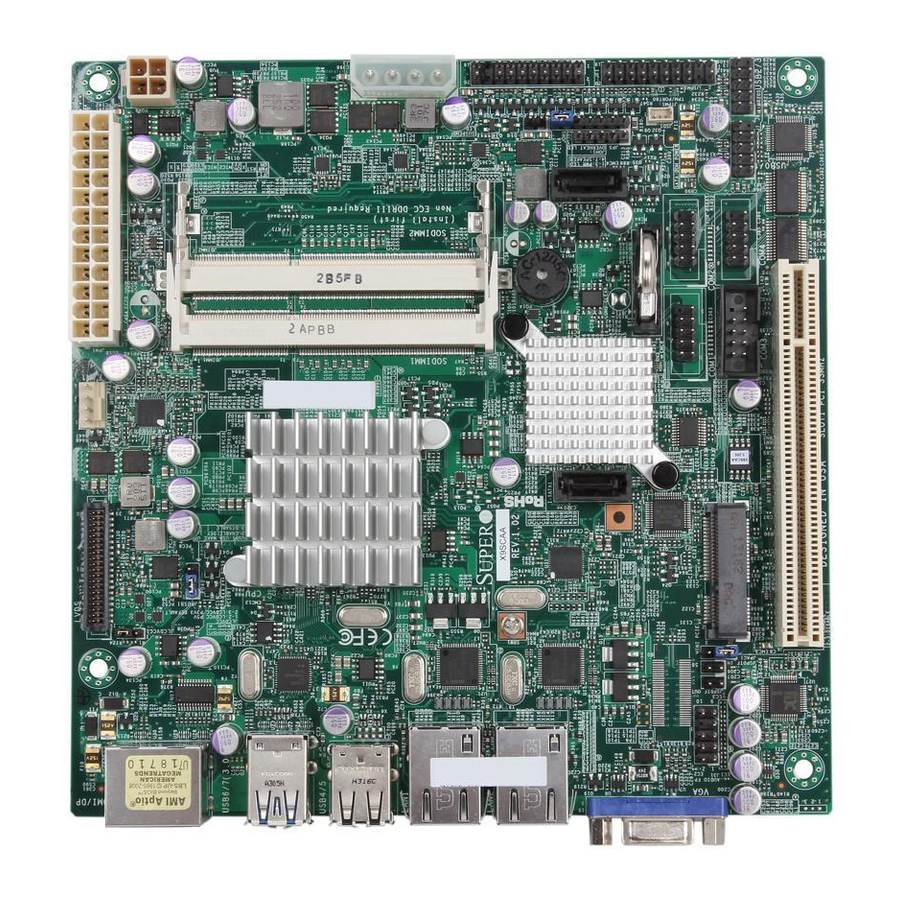
Page 14: X9Scaa Image
X9SCAA Motherboard Series User's Manual X9SCAA Image Note: All graphics and images shown in this manual were based upon the latest PCB Revision available at the time of publishing of the manual. The motherboard you've received may or may not look exactly the same as the image shown in... -
Page 15: X9Scaa-L Image
Chapter 1: Introduction X9SCAA-L Image Note: All graphics and images shown in this manual were based upon the latest PCB Revision available at the time of publishing of the manual. The motherboard you've received may or may not look exactly the same as the image shown in... -
Page 16: X9Scaa Layout
X9SCAA Motherboard Series User's Manual X9SCAA Layout JVGA1 HDMI/DP AUDIO FP JSPDIF_OUT JSPDIF_IN JPAC1 JLCDVCC1 JLCDVCC 1-2:LCDVCC P5V 2-3:LCDVCC P3V3 DEFAULT JPUSB1 PRT1 FAN1 SODIMM1 JDIMM1 JPW1 JBT1 JDIMM2 SODIMM2 (Install rst) Non ECC DDRIII Required I-SATA0 JF1: JD1: NIC1 HDD... -
Page 17: X9Scaa-L Layout
Chapter 1: Introduction X9SCAA-L Layout JVGA1 AUDIO FP JSPDIF_OUT JSPDIF_IN JPAC1 JLCDVCC1 JLCDVCC 1-2:LCDVCC P5V 2-3:LCDVCC P3V3 DEFAULT JPUSB1 PRT1 FAN1 SODIMM1 JDIMM1 JPW1 JBT1 JDIMM2 SODIMM2 (Install rst) Non ECC DDRIII Required I-SATA0 JF1: JD1: NIC1 HDD NIC2 LED X... -
Page 18: X9Scaa / X9Scaa-L Quick Reference
X9SCAA Motherboard Series User's Manual X9SCAA / X9SCAA-L Quick Reference (not drawn to scale) JVGA1 HDMI/DP AUDIO FP JSPDIF_OUT JSPDIF_IN JPAC1 JLCDVCC1 JLCDVCC 1-2:LCDVCC P5V 2-3:LCDVCC P3V3 DEFAULT JPUSB1 PRT1 FAN1 SODIMM1 JDIMM1 JPW1 JBT1 9 10 JDIMM2 SODIMM2 11 12... -
Page 19: Ports, Connectors, Led Indicators
Intel Atom N2800 Series Processor LVDS LVDS Port for VGA (Optional HDMI/Dual Display) SATA1,SATA0 Internal SATA Ports 3,32 Internal Speaker/Buzzer 34,35 SODIMM1,SODIMM2 SODIMM Memory Slots *X9SCAA Only Item # Description Color/State Status Power LED Green/Solid Power is On Suspend LED Green/Blinking... -
Page 20: Motherboard Features
Two (2) USB 2.0 Ports on the back panel (USB 4/5) Four (4) USB Ports on two headers (USB 0/1) HDMI Port (Back Panel) X9SCAA only: One (1) HDMI port VESA DisplayPort (Back Panel) X9SCAA only: One (1) VESA DisplayPort... - Page 21 Chapter 1: Introduction Serial (COM) Ports Up to four (4) fast UART 16550 connections X9SCAA: Four (4) COM headers (COM1~4). COM3 with RS422/RS485. X9SCAA-L: Two (2) COM headers (COM1, COM2) Super I/O ITE IT8760E BIOS 64 Mb SPI AMI BIOS SM Flash BIOS ®...
-
Page 22: X9Scaa Motherboard Series Block Diagram
X9SCAA Motherboard Series User's Manual X9SCAA(-L) BLOCK DIAGRAM ONLY FOR X9SCAA DDI0 HDMI connector Intel ATOM N2800 Single Channel DDI1 DP connector 2 Cores/4 Threads Non-ECC-SODIMM1 LVDS Non-ECC-SODIMM2 (DEFAULT) LVDS connector 1.86G/ 1M L2 Cache MAX. 4G SO-DIMM SUPPORTED VGA connector... -
Page 23: Chipset Overview
Chapter 1: Introduction Chipset Overview The X9SCAA Motherboard Series supports a single Intel® ATOM N2800 Series Processor processor. Built upon the functionality and the capability of the Intel NM10 Express chipset, it enables innovative form factor designs while delivering mainstream I/O technologies.. -
Page 24: 1-3 Power Configuration Settings
CPU, some are inadequate. A 2-Amp of current supply on a 5V Standby rail is strongly recommended. Note: The X9SCAA Motherboard Series alternatively supports a 4-pin 12V DC in- put power supply for embedded applications. However, the motherboard's design dictates that you only use only one power source for your application. -
Page 25: Super I/O
Chapter 1: Introduction Super I/O The Super I/O provides two high-speed, 16550 compatible serial communication ports (UARTs). Each UART includes a 16-byte send/receive FIFO, a programmable baud rate generator, complete modem control capability and a processor interrupt system. Both UARTs provide legacy speed with baud rate of up to 115.2 Kbps as well as an advanced speed with baud rates of 250 K, 500 K, or 1 Mb/s, which sup- port higher speed modems. - Page 26 X9SCAA Motherboard Series User's Manual Notes 1-14...
-
Page 27: Installation
Chapter 2: Installation Chapter 2 Installation Static-Sensitive Devices Electrostatic-Discharge (ESD) can damage electronic com ponents. To prevent dam- age to your system board, it is important to handle it very carefully. The following measures are generally sufficient to protect your equipment from ESD. Precautions •... -
Page 28: Tools Needed
Stand Offs (4 pieces) Pan head screws (4 pieces) (Only if needed) Note: The above items are not provided with this motherboard. Location of Mounting Holes There are four (4) mounting holes on the X9SCAA motherboard series. JVGA1 HDMI/DP AUDIO FP JSPDIF_OUT... -
Page 29: Installation Instructions
Chapter 2: Installation Caution: To avoid damaging the motherboard and its components, please do not use a force greater than 8 lb/inch on each mounting screw during motherboard installation. Installation Instructions Install the I/O shield into the chassis. I/O Shield Locate the mounting holes on the motherboard. -
Page 30: System Memory
2. Insert each DIMM module at an angle and snap it into place. Repeat step 1 to install SODIMM1 if needed. See instructions on the next page. Memory Support The X9SCAA Motherboard Series supports up to 4GB (2 x 2GB) of unbuffered Non-ECC DDR3 1066MHz SODIMMs in two low-profile horizontal slots. Installing and Removing DIMMs... -
Page 31: The Sodimm Socket
Chapter 2: Installation The SODIMM Socket Align Position the SODIMM module's bottom key so it aligns with the receptive point on the slot. Insert the SODIMM module vertically at about a 45 degree Press down until the module angle. locks into place. Insert this end first Press down until the module locks into... -
Page 32: Connectors And I/O Ports
X9SCAA Motherboard Series User's Manual Connectors and I/O Ports The I/O ports are color coded in conformance with the PC 99 specification. See the figure below for the colors and locations of the various I/O ports. Back Panel Connectors and I/O Ports... -
Page 33: Universal Serial Bus (Usb 0~7))
(Cables are not Ground included). See the tables on the right for Front Panel USB Headers pin definitions. Pin Definitions Pin # Definition Pin # Definition *X9SCAA only USB_N1 USB_N2 USB_P1 USB_P2 Ground Ground Backpanel USB 6,7 (3.0)* JVGA1 HDMI/DP AUDIO FP Backpanel USB 5,4 (2.0) -
Page 34: Serial Ports (Com1~4)
X9SCAA Motherboard Series User's Manual Serial Ports (COM1~4) Four COM headers (COM1, COM2, Serial Ports COM3*, COM4*) are located on the Pin Definitions motherboard. These are located next Pin # Definition Pin # Definition to the PCI slot to provide front panel access using a compatible cable (not included). -
Page 35: Vga Connector (Vga)
Chapter 2: Installation VGA Connector (VGA) VGA Port/Connector Pin Definitions A VGA connector is located next to Pin # Definition Pin # Definition LAN2 Port on the I/O back panel. Red Video +5V DC This connector is used to provide Green Video Ground (Vsync, DDC) video display to legacy VGA moni-... -
Page 36: Vesa® Displayport™ (Displayport)
X9SCAA Motherboard Series User's Manual VESA® DisplayPort™ (DisplayPort) DisplayPort is a display interface de- veloped by the VESA consortium. The VESA DisplayPort X9SCAA motherboard series supports the DisplayPort standard version 1.1 (no audio support). HDMI Port (HDMI) One HDMI (High-Definition Multimedia... -
Page 37: Front Control Panel
These connectors are designed specifically for use with Supermicro server chassis. See the figure below for the descriptions of the various control panel buttons and LED indicators. Refer to the following section for descriptions and pin definitions. -
Page 38: Front Control Panel Pin Definitions
X9SCAA Motherboard Series User's Manual Front Control Panel Pin Definitions Power LED Power LED Pin Definitions (JF1) The Power LED connection is located on Pin# Definition pins 15 and 16 of JF1. Refer to the table +3.3V on the right for pin definitions. -
Page 39: Overheat (Oh)/Fan Fail Led
Chapter 2: Installation Overheat (OH)/Fan Fail LED OH/Fan Fail Indicator Pin Definitions (JF1) Connect an LED Cable to the OH/Fan State Definition Fail connection on pins 7 and 8 of JF1 Normal to provide advanced warnings of chassis Overheat overheat or fan failure. Refer to the table Flash- Fan Fail on the right for pin definitions. -
Page 40: Connecting Cables
X9SCAA Motherboard Series User's Manual Connecting Cables This section provides brief descriptions and pin-out definitions for onboard power connectors. Be sure to use the correct cable for each header or connector. ATX Power 24-pin Connector Power Connectors (JPW1) Pin Definitions (JPW1) -
Page 41: Fan Headers
Chapter 2: Installation Fan Headers Fan Header Pin Definitions The X9SCAA Motherboard Series has Pin# Definition one fan header reserved for the system Ground (Fan1). +12V Tachometer PWM_Control Front Panel Audio Header The Front Panel Audio header is used Front Panel Audio... -
Page 42: S/Pdif In, S/Pdif Out
X9SCAA Motherboard Series User's Manual S/PDIF IN, S/PDIF OUT S/PDIF IN Pin Definitions S/PDIF (Sony®/Philips® Digital Intercon- Pin# Definition nect Format) is a specification developed S/PDIF In for carrying digital audio signals between Ground digital devices. These headers support a 2-pin input and a 2-pin output cable S/PDIF OUT for digital recording/playback devices. -
Page 43: Sata Dom Power
Chapter 2: Installation SATA DOM Power SATA DOM Power Pin Definitions The SATA DOM Power on JSD1 is used Pin# Definition to supply power to SATA Disk-on-Module (DOM) solid-state storage devices. Ground Ground Overheat/Fan Fail LED (JOH1) Overheat LED The JOH1 header is used to connect an Pin Definitions LED to provide warnings of chassis over- Pin#... -
Page 44: Mini Pci-E Slot (Mini Pcie)
X9SCAA Motherboard Series User's Manual Mini PCI-E Slot (Mini PCIE) Mini PCI-E Pin Definitions The Mini PCI-E slot is used to install a Pin# Definition Pin# Definition compatible Mini PCI-E device. Refer to +3.3Vaux the table on right for pin definitions. -
Page 45: Power Led/Speaker
Chapter 2: Installation Power LED/Speaker On the JD1 header, pins 1~3 are used for Speaker Connector Pin Definitions a power LED and pins 4~7 are used for Pin Setting Definition an external speaker. If you wish to use Pins 6-7 Internal Speaker the onboard speaker, you should close Pins 4-7... -
Page 46: Tpm Header
X9SCAA Motherboard Series User's Manual TPM Header Trusted Platform Module Header Pin Definitions The JTPM1 header is used to connect Pin # Definition Pin # Definition a Trusted Platform Module (TPM), avail- LCLK able from a third-party vendor. A TPM is... -
Page 47: Lvds Header
This signaling system can run at +12V +12V very high speeds over inexpensive copper +12V wires using low power. The LVDS bus on the X9SCAA mother- LCDVCC LCDVCC board is used to transport video data from DDC CLK DDC DATA... -
Page 48: Jumper Settings
X9SCAA Motherboard Series User's Manual Jumper Settings Explanation of Jumpers To modify the operation of the motherboard, jumpers can be used to choose between optional settings. Jumpers create shorts between two pins to change the function of the connector. Pin 1 is identified with a square solder pad on the printed circuit board. -
Page 49: Cmos Clear
Chapter 2: Installation CMOS Clear SODIMM1 JBT1 is used to clear CMOS. Instead of pins, this "jumper" consists of contact pads to pre- JBT1 vent accidental clearing of CMOS. To clear CMOS, use a metal object such as a small screwdriver to touch both pads at the same Motherboard SODIMM2... -
Page 50: Usb Wake-Up
X9SCAA Motherboard Series User's Manual USB Wake-Up USB Wake-Up Jumper Settings Use the JPUSB1 jumper to enable system Jumper Setting Definition "wake-up" via a USB device. This jumper Pins 1-2 Enabled (Default) allows you to "wake-up" the system by Pins 2-3... -
Page 51: Onboard Audio Enable
Chapter 2: Installation Onboard Audio Enable Audio Enable Jumper Settings JPAC1 allows the flexibility of enabling or Jumper Setting Definition disabling the on board audio. Please see Enabled (Default) the table on the right for the jumper settings. Disabled LVDS Voltage Select LVDS Voltage Select Jumper Settings Jumper JLCDVCC1 allows output voltage... -
Page 52: Onboard Indicators
X9SCAA Motherboard Series User's Manual Onboard Indicators GLAN Link/Speed LED Indicator LAN Port LEDs LED Color Definition Two LAN ports are located on the I/O No Connection or 10 Mbps backpanel. Each Ethernet LAN port has Green (On) 100 Mbps... -
Page 53: Onboard Power Led
Chapter 2: Installation Onboard Power LED Onboard PWR LED (PWR) LED Status An Onboard Power LED is located at Status Definition PWR on the motherboard. When PWR System Off (Soft Switch) is on, the AC power cable is connected System is Running and the system is running. -
Page 54: Serial Ata And Hdd Connections
X9SCAA Motherboard Series User's Manual Serial ATA and HDD Connections Note the following conditions when connecting the Serial ATA and hard disk drive cables: • Be sure to use the correct cable for each connector. Refer to Page 1-1 for cables that came with your shipment. -
Page 55: Troubleshooting
X9SCAA Motherboard Series User's Manual Chapter 3 Troubleshooting Troubleshooting Procedures Use the following procedures to troubleshoot your system. If you have followed all of the procedures below and still need assistance, refer to the ‘Technical Support Procedures’ and/or ‘Returning Merchandise for Service’ section(s) in this chapter. -
Page 56: Memory Errors
Before contacting Technical Support, please make sure that you have followed all the steps listed below. Also, Note that as a motherboard manufacturer, Supermicro does not sell directly to end users, so it is best to first check with your distributor or reseller for troubleshooting services. -
Page 57: Frequently Asked Questions
Question: What type of memory does my motherboard support? Answer: The X9SCAA Motherboard Series supports up to 4GB (2 x 2GB) of unbuffered Non-ECC DDR3 1066MHz SODIMMs in two low-profile horizontal slots. See Section 2-4 for details on installing memory. - Page 58 Notes: Always use the file named “ami.bat” to update the BIOS and insert a space between "ami.bat" and the filename. The BIOS-ROM-filename will bear the motherboard name (i.e., X9SCAA) and build version as the extension. For example, "X9SCAA0.526". When completed, your system will automatically reboot. If you choose the .exe file, please run the .exe file under Windows to create the BIOS flash floppy disk.
-
Page 59: Returning Merchandise For Service
X9SCAA Motherboard Series User's Manual Returning Merchandise for Service A receipt or copy of your invoice marked with the date of purchase is required before any warranty service will be rendered. You can obtain service by calling your vendor for a Returned Merchandise Authorization (RMA) number. When returning to the manufacturer, the RMA number should be prominently displayed on the outside of the shipping carton, and mailed prepaid or hand-carried. - Page 60 X9SCAA Motherboard Series User's Manual Notes...
-
Page 61: Introduction
When an option is selected in the left frame, it is highlighted in white. Often a text message will accompany it. (Note: the AMI BIOS has default text messages built in. Supermicro retains the option to include, omit, or change any of these text messages.) The AMI BIOS Setup Utility uses a key-based navigation system called "hot keys". -
Page 62: How To Start The Setup Utility
Flashing the wrong BIOS can cause irreparable damage to the system. In no event shall Supermicro be liable for direct, indirect, special, incidental, or consequential dam- ages arising from a BIOS update. If you have to update the BIOS, do not shut down or reset the system while the BIOS is updating. -
Page 63: System Overview: The Following Bios Information Will Be Displayed
Day MM/DD/YY format. The time is entered in HH:MM:SS format. (Note: The time is in the 24-hour format. For example, 5:30 P.M. appears as 17:30:00.) Supermicro X9SCAA/-L Version: This item displays the version of the BIOS used in the system. -
Page 64: Advanced Setup Configurations
X9SCAA Motherboard User's Manual Advanced Setup Configurations Use the arrow keys to select Boot Setup and hit <Enter> to access the submenu items: Aptio Setup Utility - Copyright (C) 2012 American Megatrends, Inc. Main Advanced Boot Security Save & Exit System Boot Feature Setting. -
Page 65: Interrupt 19 Capture
Chapter 4: AMI BIOS Interrupt 19 Capture Interrupt 19 is the software interrupt that handles the boot disk function. When this item is set to Enabled, the ROM BIOS of the host adaptors will "capture" Interrupt 19 at boot and allow the drives that are attached to these host adaptors to function as bootable disks. -
Page 66: Processor And Clock Options
X9SCAA Motherboard User's Manual Processor and Clock Options The top section is for informational purposes only and displays CPU information including type, speed, number of cores, etc. Warning: Take Caution when changing the Advanced settings. An incorrect value, a very high DRAM frequency or incorrect DRAM timing may cause system to become unstable. -
Page 67: Enhanced C State
Chapter 4: AMI BIOS Enhanced C State (Available when CPU C State Report is Enabled) Use this feature to enable enhanced CPU sleep state reporting. The options are Enabled and Disabled. CPU Hard C4E (Available when CPU C State Report is Enabled) Use this feature to enable the hard C4E function reporting. -
Page 68: Sata Port 0, Sata Port 1
X9SCAA Motherboard User's Manual SATA Port 0, SATA Port 1 Use this option to enable or disable the selected SATA port. The options are Disabled and Enabled. SATA Port 0, SATA Port 1 Hot Plug Set this item to Enabled to enable hot-plugging for the particular port. -
Page 69: Remote Access Configuration
Chapter 4: AMI BIOS Remote Access Configuration COM1, COM2, COM3, COM4 Use this feature to enable console redirection for COM1~COM4 ports. The op- tions are Enabled and Disabled. The default for COM1 is Enabled. The default for COM2~COM4 is Disabled. Console Redirection Settings ... -
Page 70: Serial Port For Out-Of-Band Management/Windows Emergency Management Services (Ems)
X9SCAA Motherboard User's Manual Flow Control This feature allows the user to set the flow control for Console Redirection to prevent data loss caused by buffer overflow. Send a "Stop" signal to stop send- ing data when the receiving buffer is full. Send a "Start" signal to start sending data when the receiving buffer is empty. -
Page 71: Super Io Configuration
Chapter 4: AMI BIOS Console Redirection Settings (for EMS) This feature allows the user to specify how the host computer will exchange data with the client computer, which is the remote computer used by the user. Out-of-Band-Mgmt Port Use this feature to select the port for out-of-band management. The options are COM1, COM2, COM3, COM4. -
Page 72: Serial Port 2
X9SCAA Motherboard User's Manual The options for Serial Port 1 are: Auto, IO=2D8h; IRQ=10; IO=2D8h; IRQ=10, 11; IO=2D0h; IRQ=10, 11; IO=2C8h; IRQ=10, 11; IO=2C0h; IRQ=10, 11; IO=2B8h; IRQ=10, 11 IO=2B0h; IRQ=10, 11 Serial Port 2 Select Enabled to enable the onboard serial port. The options are Enabled and Disabled. -
Page 73: Serial Port 3 Mode
Chapter 4: AMI BIOS The options for Serial Port 3 are: Auto, IO=2C8h; IRQ=10; IO=2D8h; IRQ=10, 11; IO=2D0h; IRQ=10, 11; IO=2C8h; IRQ=10, 11; IO=2C0h; IRQ=10, 11; IO=2B8h; IRQ=10, 11 IO=2B0h; IRQ=10, 11 Serial Port 3 Mode Use this feature to set the mode for this serial port. The options are RS232, RS422, and RS485. -
Page 74: Hardware Health Configuration
X9SCAA Motherboard User's Manual Hardware Health Configuration Fan Speed Control Mode This feature allows the user to decide how the system controls the speeds of the onboard fans. The CPU temperature and the fan speed are correlative. When the CPU on-die temperature increases, the fan speed will also increase for effective system cooling. -
Page 75: Network Stack
Chapter 4: AMI BIOS Network Stack Set this item to Enabled to activate the Network Stack (PXE and UEFI). The options are Enabled and Disabled. When enabled, the following options appear: Ipv4 PXE Support This feature enables Ipv4 boot support. If disabled, an Ipv4 PXE boot option will not be created. -
Page 76: Intel ® 82574L Gigabit Network Connection
X9SCAA Motherboard User's Manual 82574L Gigabit Network Connection Intel ® Use these features to configure the Ethernet device parameters. NIC Configuration Link Speed Use this feature to change the link speed and duplex for the current port. This feature cannot currently be changed using the BIOS. -
Page 77: Boot
Chapter 4: AMI BIOS Boot Use this feature to configure Boot Settings: Aptio Setup Utility - Copyright (C) 2012 American Megatrends, Inc. Main Advanced Boot Security Save & Exit Setup Prompt Timeout Sets the system boot order Driver Option Priorities Boot Option Priorities Boot Option #1 [SATA PM: WDC WD8...]... -
Page 78: Security Settings
X9SCAA Motherboard User's Manual Security Settings Aptio Setup Utility - Copyright (C) 2012 American Megatrends, Inc. Main Advanced Boot Security Save & Exit Set Administrator Password Password Description If ONLY the administrator’s password is set, then this only limits access to Setup and is only asked for when entering Setup. -
Page 79: Save & Exit
Chapter 4: AMI BIOS Save & Exit Select the Exit tab from the BIOS Setup Utility screen to enter the Exit BIOS Setup screen. Aptio Setup Utility - Copyright (C) 2012 American Megatrends, Inc. Main Advanced Boot Security Save & Exit Exit system setup without Discard Changes and Exit saving any changes. -
Page 80: Restore Optimized Defaults
X9SCAA Motherboard User's Manual Restore Optimized Defaults To set this feature, select Restore Defaults from the Exit menu and press <Enter>. These are factory settings designed for maximum system stability, but not for maximum performance. Save As User Defaults To set this feature, select Save as User Defaults from the Exit menu and press <Enter>. -
Page 81: Post Error Beep Codes
X9SCAA Motherboard Series User's Manual Appendix A POST Error Beep Codes This section lists POST (Power On Self Test) error beep codes for the AMI BIOS. POST error beep codes are divided into two categories: recoverable and terminal. This section lists Beep Codes for recoverable POST errors. - Page 82 X9SCAA Motherboard Series User's Manual Notes...
-
Page 83: Software Installation Instructions
Appendix B Software Installation Instructions B-1 Installing Software Programs The Supermicro ftp site contains drivers and utilities for your system at ftp://ftp. supermicro.com. Some of these must be installed, such as the chipset driver. After accessing the ftp site, go into the CDR_Images directory and locate the ISO file for your motherboard. -
Page 84: Configuring Superdoctor Iii
X9SCAA Motherboard Series User's Manual Note 2. When making a storage driver diskette by booting into a Driver CD, please set the SATA Configuration to "Compatible Mode" and configure SATA as IDE in the BIOS Setup. After making the driver diskette, be sure to change the SATA settings back to your original settings. - Page 85 SuperDoctor III Interface Display Screen (Remote Control) Note: SD III Software Revision 1.0 can be downloaded from our Web Site at: ftp://ftp.supermicro.com/utility/Supero_Doctor_III/. You can also download the SDIII User's Guide at: <http://www.supermicro.com/PROD- UCT/Manuals/SDIII/UserGuide.pdf>. For Linux, we will recommend using Supero Doctor II.
- Page 86 X9SCAA Motherboard Series User's Manual Notes...
- Page 87 Disclaimer The products sold by Supermicro are not intended for and will not be used in life support systems, medical equipment, nuclear facilities or systems, aircraft, aircraft devices, aircraft/emergency communication devices or other critical systems whose failure to perform be reasonably expected to result in significant injury or loss of life or catastrophic property damage.
Need help?
Do you have a question about the X9SCAA and is the answer not in the manual?
Questions and answers