Table of Contents
Advertisement
Quick Links
Download this manual
See also:
User Manual
Advertisement
Table of Contents

Subscribe to Our Youtube Channel
Related Manuals for Transcend TS-ASL3


Summary of Contents for Transcend TS-ASL3
- Page 1 TS-ASL3 TS-ASP3 USER’S MANUAL ® Intel Socket 370 Celeron ® Pentium III FC-PGA Series...
- Page 2 This freedom from liability remains in effect even if Transcend has been advised of the possibility of such damages arising from any defect or error in this manual or product.
- Page 3 Utility ezBIOS—One Click is All it Takes! Transcend is proud to inform you that your new motherboard comes with ezBIOS from Transcend. This BIOS updating program developed by Transcend will make BIOS updating easy, and enhance the security and stability of systems built with your Transcend motherboard.
-
Page 4: Table Of Contents
1.4 Specifications and Features ..................3 CHAPTER 2 HARDWARE INSTALLATION 2.1 Transcend’s TS-ASL3/TS-ASP3 Motherboard ............. 6 2.2 Layout of Transcend’s TS-ASL3/TS-ASP3 Motherboard ..........7 2.3 66/100/133MHz System Configuration ................. 8 2.4 Using Jumper JP1 to Clear CMOS ................9 2.5 VCC3 Adjust ......................... 9 2.6 Onboard Audio Setting .................... - Page 5 CHAPTER 4 BIOS UPGRADE 4.1 How to Check Your BIOS File Name and Version ..........53 4.2 Download the Correct BIOS File from Our Web Site ........53 4.3 How to Upgrade Your Motherboard BIOS ............54 Transcend Information, Inc.
-
Page 6: Chapter 1 Introduction
4. Avoid contacting the components on add-on cards, motherboards, and modules with the gold-colored connectors which plug into the expansion slots. 5. Handle system components only by their mounting brackets. 6. Keep components which are not connected to the system in their anti-static packaging whenever possible. TS-ASL3/TS-ASP3... -
Page 7: Checklist: Hardware Required For Setup
• • • • • CD-ROM Drive • • • • • External Peripherals (Optional): Printer, Speakers, Modem • • • • • Internal Peripherals (Optional): Modem, LAN Card • 1 x FDD Cable • 1 x Ultra DMA/66/100 cable Transcend Information, Inc. -
Page 8: Package Contents
815E (B-Step); FSB: 66/100/133 MHz − TS-ASP3: Intel ® 815EP (B-Step); FSB: 66/100/133 MHz • • • • • Display Cache Memory (TS-ASL3 Only) − AIMM (AGP Inline Memory Module) Card (Optional) • • • • • DRAM Memory − Supports Synchronous DRAM −... -
Page 9: Award Bios
− 6 X Master/Slave PCI Bus slots (PCI 2.2 compliant) − 1 X CNR (Communication and Networking Riser) slot • • • • • On Board VGA (TS-ASL3 only) − Full 2D/3D/Direct X acceleration − Texture-mapped 3D with point-sampled, bilinear, trilinear, and anisotropic filtering −... -
Page 10: Other Features
− Power failure resume − FWH (Firmware Hub) supports security manageability − BIOS Virus protection (warning) − Board voltage monitors for CPU core, +3.3V, +/-5.0V, +/-12.0V, VTT, 3.3VSB/5VSB − CPU overheat alarm − CPU fan auto-off in sleep mode TS-ASL3/TS-ASP3... -
Page 11: Chapter 2 Hardware Installation
INTRODUCTION CHAPTER 2 HARDWARE INSTALLATION 2.1 Transcend’s TS-ASL3/TS-ASP3 Motherboard Back panel I/O ports · Game/ MIDI port & Audio Jack · Game/ MIDI port & Audio Jack (Line-out,Line-in,MIC-in) · VGA port/Serial port COMA& · · Intel Pentium III/Celeron Tualatin Parallel printer port Main Memory ·... -
Page 12: Layout Of Transcend's Ts-Asl3/Ts-Asp3 Motherboard
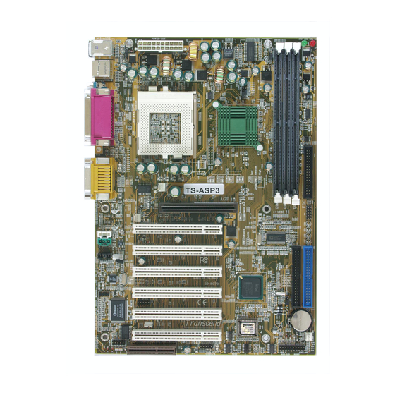
HARDWARE INSTALLATION 2.2 Layout of Transcend’s TS-ASL3/TS-ASP3 Motherboard S T B Y - L E D M E M - L E D K B M O U S E U S B T:Port 1 B:Port 2 F C - P G A... -
Page 13: 66/100/133Mhz System Configuration
FSB to 133MHz, you can select a system bus frequency from 133MHz to 166MHz. J P 4 B U S _ F r e q A U T O 1 3 3 M H z 1 0 0 M H z 6 6 M H z 66/100/133MHz FSB Configuration Jumper Transcend Information, Inc. -
Page 14: Using Jumper Jp1 To Clear Cmos
2.5 VCC3 Adjust Keep this selection fixed unless you are familiar with the system. Default is “Medium”. J P 2 8 V C C 3 Low Load M e d i u m L o a d High Load VCC3 Adjust TS-ASL3/TS-ASP3... -
Page 15: Onboard Audio Setting
CNR Audio Card. When you install a CNR card, remember that the onboard audio CODEC uses the primary channel. Therefore, if you want the onboard CODEC to work, you must set the CNR to be secondary. J P 2 Audio Enable Disable Audio Selection Jumper Transcend Information, Inc. -
Page 16: Keyboard Wake-Up
Keyboard to be able to Power Up your computer. Then, go to the”Power On Function” in “Integrated Peripherals” in BIOS to choose the setting you prefer. J P 6 K B - A W K Disable Enable Keyboard Wake-Up TS-ASL3/TS-ASP3... -
Page 17: Memory Configuration
1 6 8 - p i n U n b u f f e r e d S D R A M M o d u l e ( D I M M 3 ) 168Pin Memory DIMM Sockets Transcend Information, Inc. -
Page 18: Primary/Secondary Ide Connectors
(this may be faint and could be a dotted line) is the nearest to PIN1 (on the left as the motherboard is shown in the picture below). PIN1 Secondary IDE Connector IDE2 IDE1 Primary IDE Connector PIN1 IDE Connectors TS-ASL3/TS-ASP3... -
Page 19: Floppy Disk Drive Connector
FDD(s). Remember, as in the last section, the red stripe on the edge of the ribbon cable must be the nearest to PIN1 or your connection won’t work. PIN1 is on the left as shown below. Floppy Disk Drive Connector F D C PIN1 Floppy Disk Drive Connector Transcend Information, Inc. -
Page 20: Fan Power Connectors
These connectors support cooling fans of 500 mA (6W) or less. P O W E R - F A N CPU-FAN F A N G N D +12V Rotation CASE-FAN Fan Power Connectors TS-ASL3/TS-ASP3... -
Page 21: Wake-On-Lan Connector
MANAGEMENT SETUP in BIOS is set to “Enabled” and that your system has an ATX power supply with at least 720mA +5V standby power. W O L P M E G N D +5V Standby Wake-on-LAN Connector Transcend Information, Inc. -
Page 22: Irda-Compliant Infrared Module Connector
IrDA S I R C I R + 5 V C I R R X I R R X 5 V S B G N D I R T X IrDA Connector TS-ASL3/TS-ASP3... -
Page 23: Panel Connectors
This 4-pin connector connects to the case-mounted speaker. Pin13: Pin15: Pin17: Pin19: Hard Disk LED (2-pin HDD_LED) This 2-pin connector connects to the LED of the hard disk drive (HDD). This LED lights up when an HDD is active. Pin 6: Pin 8: Transcend Information, Inc. -
Page 24: Hardware Installation
Soft Power-Off (2-pin SOFT_OFF) Attach the PW_BTTN Switch of the panel to this connector. Use the switch to power On/Off your system. Set “Soft-Off by PWR-BTTN” in “Power Management Setup” in BIOS to either “Instant-Off” or “Delay 4 Sec.” Pin18 & Pin20 TS-ASL3/TS-ASP3... -
Page 25: Power Connector
P S O N # +5.0V G N D G N D G N D +5.0V G N D G N D -5.0V Power Good +5.0V +5.0V Standby +5.0V +12.0V PSON# : Power Supply on Power Connector Transcend Information, Inc. -
Page 26: External Back Panel I/O Ports
HARDWARE INSTALLATION 2.16 External Back Panel I/O Ports There are either 9 or 10 kinds of external connectors on the motherboard. The TS-ASL3 has a Display VGA Port onboard that is not available on the TS-ASP3. The view in the drawing shown below is the back panel of the motherboard housing of a TS-ASL3. -
Page 27: Internal Serial Port Connector
You can use the provided serial port bracket to add a serial port (COMB) for an additional serial device. C O M B G N D D T R C T S S O U T R T S S I N D S R D C D Internal Serial Port Connector COMB Transcend Information, Inc. -
Page 28: Internal Audio Connectors
G N D Left Audio Channel M o d e m - O u t (Voice from Modem) M O D E M G N D M o d e m - I n (Voice to Modem) Internal Audio Connectors TS-ASL3/TS-ASP3... -
Page 29: Internal Usb Port Connector
U S B P 2 + U S B P 3 + G N D G N D USB 3/4 Connector Congratulations! You have completed Hardware Setup! You may now continue with “Chapter 3 BIOS Setup” and turn on your PC. Transcend Information, Inc. -
Page 30: Chapter 3 Bios Setup
[Enter] key to enter its submenu. The following keys help you navigate in Setup. [Esc] Main Menu: Quit and do not save changes into CMOS RAM Other pages: Exit current page and return to Main Menu [PgUp] Increase the numeric value or make changes [PgDn] Decrease the numeric value or make changes TS-ASL3/TS-ASP3... -
Page 31: Standard Cmos Features
To control the frequency and voltage of the CPU • Load Fail-Safe Defaults To load the most basic BIOS default values required for your system to operate • Load Optimized Defaults To load the BIOS default values that are factory settings for optimal system performance Transcend Information, Inc. -
Page 32: Standard Cmos Features
To abandon all changes and exit Setup 3.3 Standard CMOS Features • Date (mm:dd:yy)/Time (hh:mm:ss) Highlight the items and use [PageUp]/[PageDown] to change the value of Date/Time. • IDE Primary/Secondary Master/Slave Press [Enter] to enter the submenu shown on the following page. TS-ASL3/TS-ASP3... - Page 33 − Auto: The BIOS automatically determines the optimal access mode. • Capacity: Disk drive capacity. Note that this size is slighty greater than the size of a formatted disk given by the disk-checking program. • Cylinder: Number of cylinders Transcend Information, Inc.
- Page 34 − All Errors: If the BIOS detects any non-fatal errors, POST stops and prompts you to take corrective action. − No Errors: POST does not stop for any error. − All, But Keyboard: If the BIOS detects any non-fatal errors except keyboard, POST stops and prompts you to take corrective action. TS-ASL3/TS-ASP3...
-
Page 35: Advanced Bios Features
HDD. NOTE: Many disk diagnostic programs that access the boot sector table can trigger the virus warning message. If you plan to run such a program, we recommend that you disable the virus warning first. Transcend Information, Inc. -
Page 36: Cpu L2 Cache Ecc Checking
“Boot Other Device” field to “Enabled”, and let the system detect the drive automatically. • Swap Floppy Drive This field is effective only in systems with two floppy drives. Selecting “Enabled” assigns physical drive B to logical drive A, and physical drive A to logical drive B. TS-ASL3/TS-ASP3... -
Page 37: Boot Up Floppy Seek
“System” boots, or only when you enter “Setup”. • OS Select For DRAM >64MB Select “OS2” only if you are running the OS/2 operating system with more than 64 MB of RAM on your system. Select “Non-OS/2” for all other operating systems. Transcend Information, Inc. -
Page 38: Advanced Chipset Features
SPD information of the Memory Module and choose the proper setting. You may manually set “SDRAM CAS Latency Time” to either “2” or “3”. • SDRAM Cycle Time Tras/Trc Select the number of SDRAM clocks used per access cycle. Settings available are: “Auto”, “7/9”, or “5/7”. TS-ASL3/TS-ASP3... -
Page 39: Delayed Transaction
When you have AIMM installed, you can set the frequency according to the speed of the SDRAM of your AIMM. Options are: “100MHz” or “133MHz”. • System Memory Frequency Default is “Auto”. When the CPU is 133MHz you can choose 100/133MHz, but when the CPU is 100MHz, only the 100MHz selection functions. Transcend Information, Inc. - Page 40 2. • RAS# Timing Set the RAS timing of the onboard display cache memory. Options are: “Fast” or “Slow”. • RAS# Precharge Timing Set the RAS precharge timing of the onboard display cache memory. Options are: “Fast” or “Slow”. TS-ASL3/TS-ASP3...
-
Page 41: Integrated Peripherals
The four IDE PIO (Programmed Input/Output) fields let you set a PIO mode (0-5) for each of the four IDE devices that the onboard IDE interface supports. Modes 0 through 5 provide successively increased performance. In “Auto” mode, the system automatically determines the best one for each device. Transcend Information, Inc. -
Page 42: Usb Keyboard Support
Any KEY: Press any key to Power On the system. − − − − − BUTTON ONLY: Power On only by pushing the button on the case (Default). − − − − − Keyboard 98: Power On system by pushing the [Power-On] key on a Keyboard 98. TS-ASL3/TS-ASP3... - Page 43 • • • • • IR Transmission Delay Consult your IR peripheral documentation to select “Enabled” or “Disabled” for the IR Transmission Delay. • • • • • UR2 Duplex Mode This item allows you to select the IR “Half” or “Full” duplex function. Transcend Information, Inc.
- Page 44 Set Joystick Game Port Address. The choices are: “Disabled”, “201” and “209”. • • • • • Midi Port Address Set Midi Port Address. The choices are: “Disabled”, “330”, “300” and ”290”. • • • • • Midi Port IRQ Assign IRQ “5” or “10” to the Midi Port. TS-ASL3/TS-ASP3...
-
Page 45: Power Management Setup
STR is an energy-saving feature. It takes only a few seconds to wake up the system and return to the previous situation. NOTE: This feature (STR) requires an ATX power supply with at least 720mA + 5V standby power for the Advanced Configuration and Power Interface (ACPI) functions. Transcend Information, Inc. - Page 46 − − − − − “V/H SYNC+BLANK”: Blanks the screen and turns off vertical and horizontal scanning. − − − − − “DPMS”: The DPMS (Display Power Management System) feature allows the BIOS to control the video display card if it supports the DPMS feature. TS-ASL3/TS-ASP3...
-
Page 47: Video Off In Suspend
NOTE: This function requires an external modem which supports the Ring Wake- Up function. • USB KB Wake-Up From S3 When your system is in S3 (Suspend to RAM) mode, you can wake-up the system by pressing the wake-up key on the USB Keyboard. Transcend Information, Inc. -
Page 48: Resume By Alarm
The settings in these fields “enable” or “disable” the detection of Primary IDE 0 IDE, floppy, serial and parallel port activities for powering down Primary IDE 1 state transition. Actually, it detects read/write to/from I/O ports. Secondary IDE 0 Secondary IDE 1 FDD, COM, LPT Port PCI PIRQ[A-D]# TS-ASL3/TS-ASP3... -
Page 49: Pnp/Pci Configuration Setup
• • • • • PCI/VGA Palette Snoop Some VGA cards, such as graphics accelerators or MPEG video cards, might not show colors properly. Select “Enabled” to correct this problem. If you don’t have such problems, leave this field “Disabled”. Transcend Information, Inc. -
Page 50: Pc Health Status
These features let you know the health status of your PC. • CPU Warning Temperature This field allows you to set the CPU warning temperature. You can choose from “50°C/ 122°F” to “70°C/158°F” or “Disabled”. TS-ASL3/TS-ASP3... -
Page 51: Shutdown Temperature
This field displays the CPU working voltage. • VTT This field displays the GTL bus voltage. • +3.3V/+5V/+12V/-12V/-5V These fields show the power supply voltages. • 3.3VSB/5VSB(V) These fields display the 3.3V/5V standby power supplied to the CMOS battery. Transcend Information, Inc. -
Page 52: Frequency/Voltage Control
100MHz to 132MHz. When JP4 is set to “133MHz”, you can select the system bus frequency from 133MHz to 166MHz. When you overclock the CPU too much, some devices on the motherboard might not function well, like onboard CODEC. When this situation happens, reduce the frequency. TS-ASL3/TS-ASP3... -
Page 53: Cpu Clock Ratio
*System bus frequency is set in the previous field (“Clock By Slight Adjust”). NOTE: Because Intel has locked the frequency ratio for new CPU settings, this field to adjust the frequency ratio is usually useless. However, it is effective for older version CPUs. Transcend Information, Inc. -
Page 54: Load Fail-Safe Defaults
NOTE: These default settings are non-optimal and disable all high performance features. 3.12 Load Optimized Defaults This option allows you to load the default values to the system configuration fields. These default values are the optimized configuration settings for the system. TS-ASL3/TS-ASP3... -
Page 55: Supervisor Password
After password entry, the screen automatically reverts to the main screen. To disable the password, press the [Enter] key when prompted to enter the password. The screen displays a message confirming that the password has been disabled. Transcend Information, Inc. -
Page 56: User Password
TS-ASL3/TS-ASP3 BIOS SETUP Forget the password? If you forget the password, you can clear it by erasing the CMOS Real Time Clock (RTC) RAM with jumper 1(JP1). See Section 2.4 Using Jumper JP1 to Clear CMOS. To erase the RTC RAM: 1. -
Page 57: Save & Exit Setup
BIOS SETUP 3.15 Save & Exit Setup Save the settings and exit the BIOS utility. 3.16 Exit Without Saving Abort the current changes and exit the BIOS utility. Transcend Information, Inc. -
Page 58: Chapter 4 Bios Upgrade
(Make sure the first 5 charactors are exactly the same as your own version if you want to upgrade your BIOS.) 4.2 Download the Correct BIOS File from Our Web Site Go to the Transcend web site: http://www.transcendusa.com/ Choose “Motherboard”. Choose “BIOS”. -
Page 59: How To Upgrade Your Motherboard Bios
Step 3: Download the updated BIOS EXE file from the web site to a floppy disk. (Ref 5.1 and 5.2) Step 4: Execute the downloaded file to decompress it. Step 5: Please read the Readme.TXT file carefully, and follow the instructions step-by-step. Continue upgrading BIOS and reconfigure your system. Transcend Information, Inc.
Need help?
Do you have a question about the TS-ASL3 and is the answer not in the manual?
Questions and answers