Table of Contents
Advertisement
Quick Links
Advertisement
Table of Contents

Subscribe to Our Youtube Channel
Related Manuals for Transcend TS-AVD1


Summary of Contents for Transcend TS-AVD1
- Page 1 TS-AVD1 USER’S MANUAL ® ® Intel Pentium II / III Series...
- Page 2 This is even if Transcend has been advised of the possibility of such damages arising from any defect or error in this manual or product.
-
Page 3: Table Of Contents
1.4 Specifications and Features .................3 CHAPTER 2 HARDWARE INSTALLATION 2.1 Transcend’s TS-AVD1 Motherboard ............... 5 2.2 Layout of Transcend’s TS-AVD1 Motherboard ..........6 2.3 CPU Installation .................... 7 2.4 66/100/133MHz System Configuration ............10 2.5 CPU Internal Frequency Ratio Setting ............10 2.6 Memory Configuration ................... - Page 4 CHAPTER 3 BIOS SETUP BIOS Setup....................21 The Main Menu ................... 21 Standard CMOS Setup................. 23 BIOS Features Setup................... 26 Chipset Features Setup................. 29 Power Management Setup ................32 PnP/PCI Configuration Setup................. 35 Integrated Peripherals ................. 38 Supervisor Password................... 41 3.10 User Password ...................
-
Page 5: Chapter 1 Introduction
INTRODUCTION CHAPTER 1 INTRODUCTION 1.1 Essential Handling Precautions IMPORTANT. Read this page before unpacking your motherboard! Power Supply Be careful! Always ensure that the computer is disconnected from the power supply when working on the motherboard and its components. Static Static electricity may cause damage to the delicate integrated circuit chips on your motherboard. -
Page 6: Checklist: Hardware Required For Setup
This motherboard package should contain the following items. Please check them as soon as you unpack. If you find any damaged or missing items, please contact your retailer. - TS-AVD1 motherboard - 1 x CD-ROM - 1 x FDD cable - 1 x Ultra DMA/66 cable - User’s Manual... -
Page 7: Specifications And Features
INTRODUCTION 1.4 Specifications and Features - Supports Intel Pentium II 233MHz~450MHz - Supports Intel Pentium III 450MHz~1.0GHz and above - Supports Intel Celeron 266MHz~533MHz (Using a converter card) Chipset - VIA 693A/596B AGPset (FSB 66/100/133MHz, Ultra DMA 33/66) DRAM Memory - Supports Synchronous DRAM - Supports Virtual Channel Memory - 3pcs of 168-pin DIMM module sockets on board... - Page 8 INTRODUCTION Award BIOS - Supports Plug-and-Play, PC98 - Supports ACPI, APM, DMI and Green Feature - Easy BIOS Recovery Wake Up Features - PS/2 Mouse and Keyboard Wake Up - Supports Wake-on-LAN function - Remote Ring Wake Up - Time Wake Up PCB Dimensions - ATX form factor, 4-layer PCB, 20.4cm x 30.5cm (8 inch x 12 inch) Switching Voltage Regulator...
-
Page 9: Chapter 2 Hardware Installation
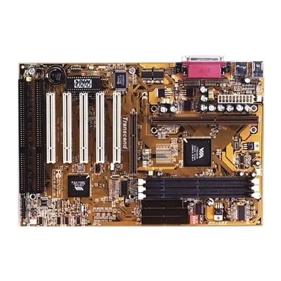
HARDWARE INSTALLATION CHAPTER 2 HARDWARE INSTALLATION 2.1 Transcend’s TS-AVD1 Motherboard I/O Port Slot 1 Memory ·2 x COM Ports & 1 x Parallel Port ·Pentium ® II MMX™ ·3 x 168-pin DIMM Sockets ·2 x USB Ports ·Up to 1.5GB SDRAM CPU 233~450MHz ·PS/2 KB Port &... -
Page 10: Layout Of Transcend's Ts-Avd1 Motherboard
HARDWARE INSTALLATION 2.2 Layout of Transcend TS-AVD1 Motherboard KB MOUSE POWER-FAN CPU-FAN PS/2 T:Mouse B:Keyboard U S B T:Port 1 B:Port 2 C O M B CPU Freq.- Ratio DIP Switch Printer 693/693A chipset C O M A 66/100/133MHz A G P... -
Page 11: Cpu Installation
HARDWARE INSTALLATION 2.3 CPU(Central Processing Unit) Installation 1. The Universal Retention Module (URM) should already be attched to your motherboard when you unpack. It consists of two separate “Ears” to support the CPU. Before installing the CPU, the ears must each be pulled upward 90 degree until they click into place when upright, as in Diagram 1. - Page 12 HARDWARE INSTALLATION Intel Celeron Intel Pentium II Intel Pentium III Processor Processor Processor (S.E.P.P) (S.E.C.C) (S.E.C.C.2) Diagram 2: The Intel Processor Type 2. There are three types of Intel Processor compatible with your motherboard’s URM. The ® Intel Celeron™ Processor (Single Edge Processor Package or SEPP), the Intel Pentium ®...
-
Page 13: Removing The Processor
HARDWARE INSTALLATION Installing the Intel Processor Step 1: Install the Processor into Slot 1 Slide the processor into the URM assembly and insert it into Slot 1, while making sure that the heat sink assembly is facing towards the chipset, as shown in the figure. Press down firmly on the CPU until it is fully seated in the Slot 1 connector. -
Page 14: 66/100/133Mhz System Configuration
HARDWARE INSTALLATION 2.4 66/100/133MHz System Configuration Jumper 1 (JP1) allows you to set the FSB (Front Side Bus) to 66, 100 or 133MHz configuration. When you set the FSB to 66MHz, you can select a system bus frequency from 66MHz to 95MHz through “CPU Host/PCI clock”... - Page 15 HARDWARE INSTALLATION CPU Internal Frequency Freq.-Ratio 233/350/466MHz 66/100/133MHz x 3.5 266/400/533MHz 66/100/133MHz x 4.0 300/450/600MHz 66/100/133MHz x 4.5 333/500/666MHz 66/100/133MHz x 5.0 366/550/733MHz 66/100/133MHz x 5.5 400/600/800MHz 66/100/133MHz x 6.0 433/650/866MHz 66/100/133MHz x 6.5 466/700/933MHz 66/100/133MHz x 7.0 500/750MHz 66/100MHz x 7.5 533/800MHz 66/100MHz...
-
Page 16: Memory Configuration
HARDWARE INSTALLATION 2.6 Memory Configuration This motherboard must be installed with DIMM (Dual Inline Memory Module). The DIMMs must be 3.3 Volt synchronous DRAM modules. The VIA Apollo Pro 133 chipset supports PC100, PC133, Virtual Channel Memory (VCM) and EDO RAM. It also supports ECC (Error Checking and Correcting) module. -
Page 17: Primary / Secondary Ide Connectors
HARDWARE INSTALLATION 2.7 Primary / Secondary IDE Connectors (Two 40-pin IDE) This mainboard supports two 40-pin IDE connectors marked as IDE1 (primary IDE channel) and IDE2 (secondary IDE channel). Each channel supports two IDE devices, making a total of four devices. -
Page 18: Keyboard Wake Up
HARDWARE INSTALLATION 2.8 Keyboard Wake Up (3-pin KB-AWK This function makes the Keyboard Power Up the system. Set this jumper to “Enable” if you would like your Keyboard to Power Up your computer. Then, go to the “Integrated Peripherals” in the BIOS SETUP MENU (please refer to page 38), and choose the setting you prefer. -
Page 19: Fan Power Connectors
HARDWARE INSTALLATION 2.10 Fan Power Connectors There are three fan power connectors on the mainboard: CPU-FAN, POWER-FAN, and CASE- FAN. Each connector provides +12V power. Make sure it is in the right orientation, or it may cause damage. These connectors support cooling fans of 500 mA (6W) or less. P O W E R - F A N F A N G N D... -
Page 20: Irda-Compliant Infrared Module Connector
HARDWARE INSTALLATION 2.12 IrDA-Compliant Infrared Module Connector (5-pin IrDA) The IrDA connector can be configured to support a wireless infrared module. With this module and application software such as Laplink or Win95 Direct Cable Connection, the user can transfer files to or from laptops(notebooks), PDAs and printers. IrDA + 5 V I R T X... - Page 21 HARDWARE INSTALLATION Keylock Lead (2-pin KEYLOCK) Use the keylock to enable or disable the keyboard. Pin4 : KEYLOCK Pin5 : Speaker Lead (4-pin SPEAKER) This 4-pin connector connects to the case-mounted speaker. Pin7 : Pin8 : Pin9 : Pin10 : SPK Suspend Mode LED Lead (2-pin S_LED) The S_LED will light when the suspend mode works.
-
Page 22: Power Connector
HARDWARE INSTALLATION 2.14 Power Connector (20-pin PWR-CONN) Make sure to plug the ATX power supply connector in the right direction. The pin definition is shown below. Make sure that your ATX power supply can support at least 720mA on the standby lead. -
Page 23: Clear Cmos Jumper
HARDWARE INSTALLATION 1. PS/2 Mouse 4. Parallel Port (Printer) 3. USB1 3. USB2 2. PS/2 Keyboard 5 . C O M B 5 . C O M A Back Panel I/O Ports 2.16 Clear CMOS Jumper (3-pin JP4) To clear the CMOS data, you should turn off your computer power and short pin1 and pin2 of JP4. -
Page 24: Sb-Link Connector
HARDWARE INSTALLATION 2.17 SB-Link Connector SB-Link connector is used only for Creative ® PCI sound cards. If your sound card supports this function, attach the SB-Link cable to this connector. P C P C I G N T N D G N D P C P C I R E Q N D G N D S E P I R Q... -
Page 25: Chapter 3 Bios Setup
BIOS SETUP CHAPTER 3 BIOS SETUP 3.1 BIOS Setup Award BIOS has a built-in Setup program that allows users to modify the basic system configuration. This information is stored in CMOS RAM. So it can retain the Setup information when the power is turned off. When the battery of CMOS fails, it will cause the data to be lost. When that happens, you should set up your configuration parameters again after replacing the battery. - Page 26 BIOS SETUP [F1] General help, only for Status Page Setup Menu and Option Page Setup Menu [F2] Change color from total 16 colors [F2] to select color forward [Shift + F2] to select color backward [F3] Calendar, only for Status Page Setup Menu [F5] Restore the previous CMOS value from CMOS, only for Option Page Setup Menu [F6]...
-
Page 27: Standard Cmos Setup
BIOS SETUP SUPERVISOR / USER PASSWORD To change, set, or disable a password. IDE HDD AUTO DETECTION Automatically detect and configure IDE hard disk parameters. SAVE & EXIT SETUP Save settings in nonvolatile CMOS RAM and exit Setup. EXIT WITHOUT SAVING Abandon all changes and exit Setup. - Page 28 BIOS SETUP 1. Match the specifications of your installed IDE hard drive(s) with the preprogrammed values for drive type 1 through 45. 2. Select “USER” and enter values into each drive parameter field. 3. Use the “IDE HDD AUTO DETECTION” function in Main Menu. Here are the brief explanation of drive specifications.
- Page 29 BIOS SETUP Drive A / Drive B Select the correct specifications of the diskette drive(s) installed in the computer. - None : No diskette drive installed. - 360K, 5.25 in. : 5-1/4 inch standard drive; 360 kilobyte capacity. - 1.2M, 5.25 in.: 5-1/4 inch high-density drive; 1.2 megabyte capacity. - 720K, 3.5 in.
-
Page 30: Bios Features Setup
BIOS SETUP 3.4 BIOS Features Setup This “BIOS Features Setup” option allows you to improve your system performance and set up system features according to your preference. Virus Warning When the function is enabled, you will receive a warning message if a program (specifically, a virus) attempts to write to the boot sector or the partition table of the hard disk drive. - Page 31 BIOS SETUP CPU L2 Cache ECC Checking Select “Enabled” to make sure the data is accurate. Quick Power On Self Test Select “Enabled” to reduce the amount of time required to run the Power On Self Test (POST). A quick POST skips certain steps. We recommend that you normally disable quick POST.
- Page 32 BIOS SETUP Typematic Rate Setting When this function is”Disabled”, the following two items ( “Typematic Rate” and “Typematic Delay” ) are irrelevant. Keystrokes repeat at a rate determined by the keyboard controller in your system. When this function is “Enabled”, you can select a typematic rate and typematic delay.
-
Page 33: Chipset Features Setup
BIOS SETUP C8000-DFFFF Shadow You can shadow the ROM on other expansion cards by setting these fields. If you install other expansion cards with ROMs, you need to know which address the ROMs use specifically. Shadowing a ROM reduces the memory available between 640K and 1024K depends on the used amount. - Page 34 BIOS SETUP DRAM Clock This sets the clock frequency of the DRAMs. The default value is “Host Clock”. You can select “HCLK+33M” if your DRAM modules are faster than the CPU (Ex. a 66MHz FSB CPU with a PC100 SDRAM, or a 100MHz FSB CPU with PC133 SDRAM); or select “HCLK-33M” for a faster CPU with slower SDRAMs.
- Page 35 BIOS SETUP CPU Host/PCI Clock This function allows you to set the FSB frequency of the CPU and the speed of the PCI bus. When JP1 is set to 66MHz, the default FSB is 66MHz, and there are several options under 100MHz available.
-
Page 36: Power Management Setup
BIOS SETUP 3.6 Power Management Setup The Power Management Setup allows you to configure your system to save energy most efficiently while operating in a manner consistent with your own style of computer use. ACPI function This item allows you to enable /disable the Advanced Configuration and Power Interface (ACPI) functions. - Page 37 BIOS SETUP PM Control by APM When “Yes”, an Advanced Power Management device will be activated to enhance the Max. Power Saving mode and stop the CPU internal clock. Video Off Method Determines the manner in which the monitor is blanked. -V/H SYNC+BLANK : System turns off vertical and horizontal synchronization ports and writes blanks to the video buffer.
- Page 38 BIOS SETUP HDD Power Down After the selected period of driver inactivity(1 to 15 minutes), the hard disk drive will Power Down while all other devices remain active. Doze Mode After the selected period of system inactivity (1 minute to 1 hour), the CPU clock runs at a slower speed while all other devices still operate at full speed.
-
Page 39: Pnp/Pci Configuration Setup
BIOS SETUP Ring Wake Up This allows either setting of “Enabled” or “Disabled” to Power Up the computer when the MODEM receives a call and the computer is in the soft-off mode. Time Wake Up This feature can Power On your computer at a time you have selected. Date/Time Set the date and time to Power On the system. - Page 40 BIOS SETUP PnP OS Installed This field allows you to use a Plug-and-Play (PnP) operating system to configure the PCI bus slots instead of using the BIOS. Thus interrupts may be re-assigned by the OS when “Yes” is selected. When a non-PnP OS is installed to prevent re-assigning of interrupt settings, select the default setting of “No”.
- Page 41 BIOS SETUP - PCI/ISA PnP devices, whether designed for PCI or ISA bus architecture, compliant with the Plug and Play standard. DMA-n Assigned to When resources are controlled manually, assign each system DMA channel as one of the following types, depending on the type of device using the DMA. - Legacy ISA Devices, requiring a specific DMA channel, compliant with the original PCAT bus specification.
-
Page 42: Integrated Peripherals
BIOS SETUP Assign IRQ For USB When “Enabled”, BIOS will assign an IRQ channel for USB controller. Assign IRQ For VGA Select “Enabled” only if your VGA card requires an assigned IRQ. Most ordinary cards do not; but some high-end cards with video capture function do. Consult your VGA documentation to set this field. - Page 43 BIOS SETUP If your IDE hard drive supports Block Mode (most new drives do), select “Enabled” for automatic detection of the optimal number of Block Read/Write per sector the drive can support. Primary/Secondary Master/Slave PIO The four IDE PIO (Programmed Input/Output) fields let you set a PIO mode (0-4) for each of the four IDE devices that the onboard IDE interface supports.
- Page 44 BIOS SETUP Onboard FDC Controller You can use this function to enable or disable the onboard FDC controller. Onboard Serial Port 1/Port 2 Select an address and the corresponding interrupt for each of the first and second serial ports. The choice: “3F8/IRQ4”, “2F8/IRQ3”, “3E8/IRQ4”, “2F8/IRQ3”, “Disabled” and “Auto”. The second serial port shares resources (address and IRQ) with IrDA.
-
Page 45: Supervisor Password
BIOS SETUP EPP Mode Select There are two versions of 1.7 and 1.9 available for EPP Mode. While setting the version, check if the device connected to the parallel port needs the specified version or not. If not, it’s recommended to select version 1.9. OnChip USB Select “Enabled”... -
Page 46: User Password
BIOS SETUP 3.10 User Password This option allows you to a set the password to prevent others from changing the BIOS setting of your system. This operation is the same as Supervisor Password. 3.11 IDE HDD Auto Detection Use the BIOS utility to detect the HDD type automatically. Press “Y” to accept, “N” to reject, and “ESC”... -
Page 47: Save & Exit Setup
BIOS SETUP 3.12 Save & Exit Setup Save the setting and exit the BIOS utility. 3.13 Exit Without Saving Abort the current change and exit the BIOS utility. -
Page 48: Load Bios Defaults
BIOS SETUP 3.14 Load BIOS Defaults NOTE: This option allows you to load the troubleshooting default values permanently stored in the BIOS ROM. These default settings are non-optimal and disable all high performance features. 3.15 Load Setup Defaults This option allows you to load the default values to the system configuration fields. These default values are the optimized configuration settings for the system. -
Page 49: Chapter 4 Bios Upgrade
BIOS.) 4.2 Download Correct BIOS File from Web Please enter Transcend’s website : http://www.transcendusa.com/ Choose BIOS upgrade environment. The BIOS file name consists of 5 characters. Check the exact BIOS to download. Your BIOS file name must completely match the one shown on our website. -
Page 50: How To Upgrade Your Motherboard Bios
BIOS UPGRADE 4.3 How to Upgrade Your Motherboard BIOS Please follow these 5 steps listed below to updata your BIOS. Step 1: Make a record of your original or existing BIOS Setup parameters. -Press [Del] during the power On self Test to enter BIOS Setup Program when you start your system.
Need help?
Do you have a question about the TS-AVD1 and is the answer not in the manual?
Questions and answers