Table of Contents
Advertisement
Intel
D865GBF/D865GLC
Technical Product Specification
®
The Intel
Desktop Board D865GBF/D865GLC may contain design defects or errors known as errata that may cause the product to deviate from published specifications. Current
characterized errata are documented in the Intel Desktop Board D865GBF/D865GLC Specification Update.
®
Desktop Board
April 2003
Order Number: C32634-001
Advertisement
Table of Contents

Related Manuals for Intel BLKD865GBF


Summary of Contents for Intel BLKD865GBF
- Page 1 Order Number: C32634-001 ® The Intel Desktop Board D865GBF/D865GLC may contain design defects or errors known as errata that may cause the product to deviate from published specifications. Current characterized errata are documented in the Intel Desktop Board D865GBF/D865GLC Specification Update.
-
Page 2: Revision History
Contact your local Intel sales office or your distributor to obtain the latest specifications before placing your product order. Copies of documents which have an ordering number and are referenced in this document, or other Intel literature, may be obtained from: Intel Corporation P.O. -
Page 3: Intended Audience
Preface This Technical Product Specification (TPS) specifies the board layout, components, connectors, ® power and environmental requirements, and the BIOS for these Intel Desktop Boards: D865GBF and D865GLC. It describes the standard product and available manufacturing options. Intended Audience The TPS is intended to provide detailed, technical information about the Desktop Boards D865GBF and D865GLC and their components to the vendors, system integrators, and other engineers and technicians who need this level of information. - Page 4 Intel Desktop Board D865GBF/D865GLC Technical Product Specification WARNING Warnings indicate conditions, which if not observed, can cause personal injury. Other Common Notation Used after a signal name to identify an active-low signal (such as USBP0#) (NxnX) When used in the description of a component, N indicates component type, xn are the relative coordinates of its location on the Desktop Boards D865GBF and D865GLC, and X is the instance of the particular part at that general location.
-
Page 5: Table Of Contents
Processor ........................21 System Memory ......................22 1.7.1 Memory Configurations ................24 ® Intel 865G Chipset ....................29 1.8.1 Intel 865G Graphics Subsystem..............30 1.8.2 Universal 0.8 V / 1.5 V AGP 3.0 Connector..........38 1.8.3 USB......................39 1.8.4 IDE Support ....................39 1.8.5 Real-Time Clock, CMOS SRAM, and Battery..........41 I/O Controller ......................41... - Page 6 Intel Desktop Board D865GBF/D865GLC Technical Product Specification 2 Technical Reference Introduction.........................59 Memory Resources ....................59 2.2.1 Addressable Memory ...................59 2.2.2 Memory Map ....................61 DMA Channels ......................61 Fixed I/O Map......................62 PCI Configuration Space Map ..................63 Interrupts ........................65 PCI Interrupt Routing Map ..................66 Connectors .........................68...
- Page 7 Network Boot....................102 3.8.3 Booting Without Attached Devices .............102 3.8.4 Changing the Default Boot Device During POST........102 ® Fast Booting Systems with Intel Rapid BIOS Boot ..........103 3.9.1 Peripheral Selection and Configuration ............103 3.9.2 Intel Rapid BIOS Boot ................103 3.10 BIOS Security Features....................104 4 BIOS Setup Program Introduction.......................105...
- Page 8 Intel Desktop Board D865GBF/D865GLC Technical Product Specification Figures Desktop Board D865GBF Components ..............14 Desktop Board D865GLC Components ..............15 Block Diagram ......................16 Memory Channel Configuration ..................24 Examples of Dual Channel Configuration with Dynamic Mode ........25 Example of Dual Channel Configuration without Dynamic Mode ........26 Examples of Single Channel Configuration with Dynamic Mode.........27...
- Page 9 Contents LAN Connector LED States ..................47 LAN Connector LED States ..................48 Effects of Pressing the Power Switch .................51 Power States and Targeted System Power ..............51 Wake-up Devices and Events..................52 Fan Connector Function/Operation................54 System Memory Map....................61 DMA Channels ......................61 I/O Map ........................62 PCI Configuration Space Map ..................63 PCI Configuration Space Bus Number Options ............64 Interrupts ........................65...
- Page 10 Intel Desktop Board D865GBF/D865GLC Technical Product Specification Drive Configuration Submenu...................114 SATA/PATA Submenus....................117 Floppy Configuration Submenu ................118 Event Log Configuration Submenu ................119 Video Configuration Submenu ..................120 USB Configuration Submenu..................121 Chipset Configuration Submenu ................122 Fan Control Configuration Submenu ................124 Hardware Monitoring Display..................125 Security Menu ......................126...
-
Page 11: Product Description
1.12 Hardware Management Subsystem................48 1.13 Power Management ....................50 1.1 Board Differences ® This TPS describes these Intel Desktop Boards: D865GBF and D865GLC. The Desktop Boards are identical with the exception of the items listed in Table 1. Table 1. Summary of Board Differences D865GBF ATX Form Factor (11.60 inches by 9.60 inches [294.64 millimeters by... -
Page 12: Overview
One diskette drive interface PS/2* keyboard and mouse ports LAN Support The board provides one of the following: ® Gigabit (10/100/1000 Mbits/sec) LAN subsystem using the Intel 82547EI Platform LAN Connect (PLC) device ® 10/100 Mbits/sec LAN subsystem using the Intel... -
Page 13: Manufacturing Options
1.2.2 Manufacturing Options Table 3 describes the manufacturing options on the Desktop Boards D865GBF and D865GLC. Not every manufacturing option is available in all marketing channels. Please contact your Intel representative to determine which manufacturing options are available to you. -
Page 14: Board Layouts
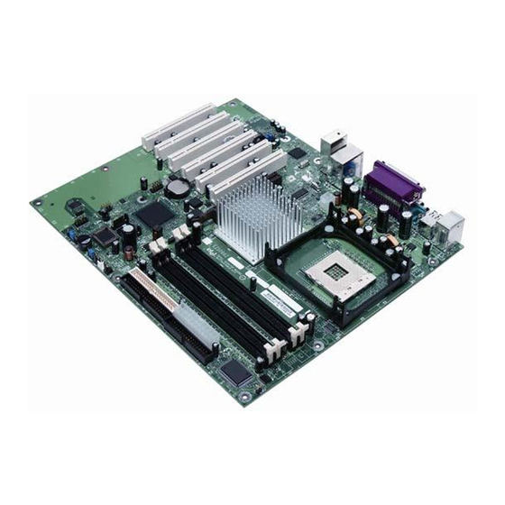
Intel Desktop Board D865GBF/D865GLC Technical Product Specification 1.2.3 Board Layouts Figure 1 shows the location of the major components on the Desktop Board D865GBF. OM15914 Auxiliary line-in connector Diskette drive connector Audio codec Parallel ATA IDE connectors Front panel audio connector... -
Page 15: Desktop Board D865Glc Components
Front panel connector Processor fan connector Serial ATA connectors Intel 82865G GMCH Front panel USB connector DIMM Channel A sockets Intel 82801EB I/O Controller Hub (ICH5) DIMM Channel B sockets Front panel USB connector I/O controller Battery Power connector PCI bus add-in card connectors... -
Page 16: Block Diagram
Intel Desktop Board D865GBF/D865GLC Technical Product Specification 1.2.4 Block Diagram Figure 3 is a block diagram of the major functional areas of the Desktop Boards D865GBF and D865GLC. = connector or socket Back Panel/ Front Panel USB Ports Parallel ATA IDE... -
Page 17: Online Support
Native USB 2.0 support has been tested with drivers for Windows 2000 (with Service Pack 3) and Windows XP (with Service Pack 1) and is not currently supported by any other operating system in the list above. Check Intel’s Desktop Board website for possible driver updates for other operating systems. -
Page 18: Design Specifications
Intel Desktop Board D865GBF/D865GLC Technical Product Specification 1.5 Design Specifications Table 4 lists the specifications applicable to the Desktop Boards D865GBF and D865GLC. Table 4. Specifications Reference Specification Version, Revision Date, The information is Name Title and Ownership available from…... - Page 19 PCI Bus Power Revision 1.1, http://www.pcisig.com/speci Management Interface December 18, 1998, fications Specification PCI Special Interest Group. Plug and Plug and Play BIOS Version 1.0a, http://www.microsoft.com/h Play Specification May 5, 1994, wdev/tech/PnP/default.asp Compaq Computer Corporation, Phoenix Technologies Limited, and Intel Corporation. continued...
- Page 20 Intel Desktop Board D865GBF/D865GLC Technical Product Specification Table 4. Specifications (continued) Reference Specification Version, Revision Date The information is Name Title and Ownership available from… Preboot Execution Version 2.1, ftp://download.intel.com/lab Environment September 20, 1999, s/manage/wfm/download/p Intel Corporation. xespec.pdf SFX/SFX12V Power Version 2.0,...
-
Page 21: Processor
Intel Pentium 4 processors in an mPGA478 processor socket with a 400/533/800 MHz system Intel Celeron processors in an mPGA478 processor socket with a 400 MHz system bus See the Intel web site listed below for the most up-to-date list of supported processors. For information about…... -
Page 22: System Memory
Intel Desktop Board D865GBF/D865GLC Technical Product Specification 1.7 System Memory The Desktop Boards D865GBF and D865GLC have four DIMM sockets and support the following memory features: 2.5 V (only) 184-pin DDR SDRAM DIMMs with gold-plated contacts Unbuffered, single-sided or double-sided DIMMs with the following restriction: Double-sided DIMMS with x16 organization are not supported. -
Page 23: Supported Memory Configurations
Product Description Table 6 lists the supported DIMM configurations. Table 6. Supported Memory Configurations DIMM DDR SDRAM DDR SDRAM Organization Number of DDR Capacity Configuration Density Front-side/Back-side SDRAM Devices 64 MB 64 Mbit 8 M x 8/empty 64 MB 128 Mbit 8 M x 16/empty 128 MB 64 Mbit... -
Page 24: Memory Configurations
Intel Desktop Board D865GBF/D865GLC Technical Product Specification 1.7.1 Memory Configurations The Intel 82865PE MCH component provides two features for enhancing memory throughput: Dual Channel memory interface. The board has two memory channels, each with two DIMM sockets, as shown in Figure 4 Dynamic Addressing Mode. -
Page 25: Examples Of Dual Channel Configuration With Dynamic Mode
Product Description Dual Channel Configuration with Dynamic Mode (All DIMMs matched) Channel A - DIMM 0 Channel B - DIMM 0 Example Intel Channel B - DIMM 1 Channel A - DIMM 1 82865G GMCH Channel A - DIMM 0... -
Page 26: Example Of Dual Channel Configuration Without Dynamic Mode
Intel Desktop Board D865GBF/D865GLC Technical Product Specification Dual Channel Configuration without Dynamic Mode - DIMMs not matched within channel - DIMMs match Channel A to Channel B Channel A - DIMM 0 Channel B - DIMM 0 Intel Channel A - DIMM 1... -
Page 27: Examples Of Single Channel Configuration With Dynamic Mode
Single Channel Configuration with Dynamic Mode (Single DIMM or DIMMs matched within Channel) Channel A - DIMM 0 Channel B - DIMM 0 Example Intel Channel A - DIMM 1 Channel B - DIMM 1 82865G GMCH Channel A - DIMM 0... -
Page 28: Examples Of Single Channel Configuration Without Dynamic Mode
Intel Desktop Board D865GBF/D865GLC Technical Product Specification Single Channel Configuration without Dynamic Mode (DIMMs not matched) Channel A - DIMM 0 Channel B - DIMM 0 Example Intel Channel B - DIMM 1 Channel A - DIMM 1 82865G GMCH... -
Page 29: Intel ® 865G Chipset
1.8 Intel ® 865G Chipset The Intel 865G chipset consists of the following devices: Intel 82865G Graphics and Memory Controller Hub (GMCH) with Accelerated Hub Architecture (AHA) bus Intel 82801EB I/O Controller Hub (ICH5) with AHA bus Firmware Hub (FWH) The GMCH is a centralized controller for the system bus, the memory bus, the AGP bus, and the Accelerated Hub Architecture interface. -
Page 30: Intel 865G Graphics Subsystem
The Intel 865G chipset contains two separate, mutually exclusive graphics options. Either the Intel Extreme Graphics 2 controller (contained within the 82865G GMCH) is used, or an AGP add-in card can be used. When an AGP add-in card is installed, the Intel Extreme Graphics 2 controller is disabled. -
Page 31: Direct Draw Supported Modes
Product Description Table 8. Direct Draw Supported Modes Resolution Color Palette Refresh Frequency (Hz) Notes 256 colors 320 x 200 64 K colors 16 M colors 256 colors 320 x 240 64 K colors 16 M colors 256 colors 352 x 480 64 K colors 16 M colors 256 colors... -
Page 32: Video Bios Video Modes Supported For Analog Crts
Intel Desktop Board D865GBF/D865GLC Technical Product Specification Table 9. Video BIOS Video Modes Supported for Analog CRTs Available Refresh Resolution Color Palette Frequencies (Hz) Notes 16 colors 320 x 200 T, G, B 256 colors G, B 16 colors 320 x 350... -
Page 33: Supported Modes For Ddr400/Ddr333 Dual Channel Configuration
Product Description Table 10. Supported Modes for DDR400/DDR333 Dual Channel Configuration 2D= Display only 2D+0 = 2D display + full screen Resolution 8-Bit Color 2D+0 2D+0 2D+0 2D+0 2D+0 2D+0 2D+0 2D+0 2D+0 2D+0 2D+0 2D+0 2D+0 2D+0 2D+0 2D+0 2D+0 2D+0 2D+0... -
Page 34: Supported Modes For Ddr266 Dual Channel And Ddr333/Ddr400 Single Channel Configurations
Intel Desktop Board D865GBF/D865GLC Technical Product Specification Table 11. Supported Modes for DDR266 Dual Channel and DDR333/DDR400 Single Channel Configurations 2D= Display only 2D+0 = 2D display + full screen 2D+D = 2D display + DVD content Resolution 8-Bit Color... -
Page 35: Supported Modes For Ddr266 Single Channel Configuration
Product Description Table 12. Supported Modes for DDR266 Single Channel Configuration 2D= Display only 2D+0 = 2D display + full screen Resolution 8-Bit Color 2D+0 2D+0 2D+0 2D+0 2D+0 2D+0 2D+0 2D+0 2D+0 2D+0 2D+0 2D+0 2D+0 2D+0 2D+0 2D+0 2D+0 2D+0 2D+0... - Page 36 1.8.1.4 Zone Rendering Technology (ZRT) The Intel Extreme Graphics 2 Controller supports Zone Rendering Technology (ZRT). ZRT is a process by which the screen is divided into several zones. Each zone is completely cached and rendered on chip before being written to the frame buffer. The benefits of ZRT include the...
- Page 37 The Intel Pentium 4 processor in combination with the Intel 82865G GMCH optimizes performance so that the video output is smooth without leaving any visual artifacts.
-
Page 38: Universal 0.8 V / 1.5 V Agp 3.0 Connector
Intel Desktop Board D865GBF/D865GLC Technical Product Specification accessed by an ADD card. ADD cards can support up to two display devices with the following configurations: TV-Out Transition Minimized Differential Signaling (TMDS) Low Voltage Differential Signaling (LVDS) Single device operating in dual channel mode INTEGRATOR’S NOTES... -
Page 39: Usb
Native USB 2.0 support has been tested with drivers for Windows 2000 (with Service Pack 3) and Windows XP (with Service Pack 1) and is not currently supported by any other operating system. Check Intel’s Desktop Board website for possible driver updates for other operating systems. - Page 40 Intel Desktop Board D865GBF/D865GLC Technical Product Specification NOTE ATA-66 and ATA-100 are faster timings and require a specialized cable to reduce reflections, noise, and inductive coupling. The Parallel ATA IDE interfaces also support ATAPI devices (such as CD-ROM drives) and ATA devices using the transfer modes listed in Section 4.4.4.1 on page 116.
-
Page 41: Real-Time Clock, Cmos Sram, And Battery
Product Description 1.8.4.3 SCSI Hard Drive Activity LED Connector (Optional) The SCSI hard drive activity LED connector is a 1 x 2-pin connector that allows an add-in hard drive controller to use the same LED as the onboard IDE controller. For proper operation, this connector should be wired to the LED output of the add-in hard drive controller. -
Page 42: Serial Port
Intel Desktop Board D865GBF/D865GLC Technical Product Specification 1.9.1 Serial Port The boards have one serial port connector located on the back panel. The serial port supports data transfers at speeds up to 115.2 kbits/sec with BIOS support. For information about... -
Page 43: Audio Subsystem
Split digital/analog architecture for improved S/N (signal-to-noise) ratio: > 94 dB 1.10.1 Audio Subsystem Software Audio software and drivers are available from Intel’s World Wide Web site. For information about Refer to Obtaining audio software and drivers Section 1.3, page 17... -
Page 44: Adapter For S/Pdif Back Panel Connector
Intel Desktop Board D865GBF/D865GLC Technical Product Specification INTEGRATOR’S NOTE To access the S/PDIF signal with the 5.1 Digital Shared Jack option, connect an 1/8-inch stereo phone plug to RCA jack adapter/splitter as shown in Figure 11. Connect to S/PDIF output... -
Page 45: Audio Connectors
Product Description 1.10.3 Audio Connectors 1.10.3.1 Front Panel Audio Connector A 2 x 5-pin connector provides mic in and line out signals for front panel audio connectors. For information about Refer to The location of the connector Figure 19, page 71 The signal names of the front panel audio connector Table 28, page 72 NOTE... -
Page 46: Lan Subsystem
PCI power management Supports ACPI technology Supports LAN wake capabilities 1.11.1 10/100 Mbits/sec LAN Subsystem The 10/100 Mbits/sec LAN subsystem includes the ICH5 (with its CSMA/CD interface), the Intel 82562EZ PLC, and an RJ-45 LAN connector with integrated status LEDs ® 1.11.1.1... -
Page 47: Gigabit Lan Subsystem
Intel 82547EI provides the following functions: Basic 10/100/1000 Ethernet LAN connectivity Communication Streaming Architecture (CSA) port provides higher throughput and lower latencies than the Intel 82562EZ device, resulting in up to 30% higher bus throughput (up to wirespeed) Full device driver compatibility... -
Page 48: Lan Subsystem Software
100 Mbit/sec data rate is selected. Orange 1000 Mbit/sec data rate is selected. 1.11.3 LAN Subsystem Software LAN software and drivers are available from Intel’s World Wide Web site. For information about Refer to Obtaining LAN software and drivers Section 1.3, page 17 1.12 Hardware Management Subsystem... -
Page 49: Thermal Monitoring
Product Description 1.12.2 Thermal Monitoring Figure 15 shows the location of the sensors and fan connectors. OM15916 Item Description Thermal diode, located on processor die Remote ambient temperature sensor Ambient temperature sensor (internal to hardware monitoring and fan control ASIC) Processor fan Rear chassis fan Front chassis fan... -
Page 50: Fan Monitoring
Intel Desktop Board D865GBF/D865GLC Technical Product Specification 1.12.3 Fan Monitoring ® Fan monitoring can be implemented using Intel Active Monitor, LANDesk* software, or third- party software. The level of monitoring and control is dependent on the hardware monitoring ASIC used with the Desktop Board. -
Page 51: Effects Of Pressing The Power Switch
Product Description Table 15 lists the system states based on how long the power switch is pressed, depending on how ACPI is configured with an ACPI-aware operating system. Table 15. Effects of Pressing the Power Switch …and the power switch is If the system is in this state…... -
Page 52: Wake-Up Devices And Events
Intel Desktop Board D865GBF/D865GLC Technical Product Specification Table 16. Power States and Targeted System Power (continued) Processor Targeted System (Note 1) Global States Sleeping States States Device States Power (Note 2) G2/S5 S5 – Soft off. No power D3 – no power Power <... -
Page 53: Hardware Support
Product Description 1.13.2 Hardware Support CAUTION Ensure that the power supply provides adequate +5 V standby current if LAN wake capabilities and Instantly Available PC technology features are used. Failure to do so can damage the power supply. The total amount of standby current required depends on the wake devices supported and manufacturing options. -
Page 54: Fan Connector Function/Operation
Intel Desktop Board D865GBF/D865GLC Technical Product Specification 1.13.2.2 Fan Connectors Table 18 summarizes the function/operation of the fan connectors. Table 18. Fan Connector Function/Operation Connector Description Processor fan +12 V DC connection for a processor fan or active fan heatsink. - Page 55 Product Description 1.13.2.4 Instantly Available PC Technology CAUTION For Instantly Available PC technology, the +5 V standby line for the power supply must be capable of providing adequate +5 V standby current. Failure to provide adequate standby current when implementing Instantly Available PC technology can damage the power supply. Instantly Available PC technology enables the Desktop Boards D865GBF and D865GLC to enter the ACPI S3 (Suspend-to-RAM) sleep-state.
-
Page 56: Location Of The Standby Power Indicator Led On The D865Gbf Board
Intel Desktop Board D865GBF/D865GLC Technical Product Specification 1.13.2.5 +5 V Standby Power Indicator LED The +5 V standby power indicator LED shows that power is still present even when the computer appears to be off. Figure 16 shows the location of the standby power indicator LED on the D865GBF board. - Page 57 Product Description 1.13.2.6 Resume on Ring The operation of Resume on Ring can be summarized as follows: Resumes operation from ACPI S1 or S3 states Detects incoming call similarly for external and internal modems Requires modem interrupt be unmasked for correct operation 1.13.2.7 Wake from USB USB bus activity wakes the computer from ACPI S1 or S3 states.
- Page 58 Intel Desktop Board D865GBF/D865GLC Technical Product Specification...
-
Page 59: Introduction
2 Technical Reference What This Chapter Contains Introduction.........................59 Memory Resources ....................59 DMA Channels ......................61 Fixed I/O Map......................62 PCI Configuration Space Map ..................63 Interrupts ........................65 PCI Interrupt Routing Map ..................66 Connectors .........................68 Jumper Blocks......................83 2.10 Mechanical Considerations..................85 2.11 Electrical Considerations ....................88 2.12 Thermal Considerations....................89 2.13 Reliability ........................92 2.14 Environmental ......................92... -
Page 60: Detailed System Memory Address Map
Intel Desktop Board D865GBF/D865GLC Technical Product Specification program will further reduce the amount of memory available to the operating system. Figure 17 shows a schematic of the system memory map. All installed system memory can be used when there is no overlap of system addresses. For example, all of the system address space can be utilized on a system that has 2 GB of installed system memory, AGP aperture set for 256 MB, and the PCI cards are requesting 200 MB of system address space. -
Page 61: Memory Map
Technical Reference 2.2.2 Memory Map Table 19 lists the system memory map. Table 19. System Memory Map Address Range (decimal) Address Range (hex) Size Description 1024 K - 4194304 K 100000 - FFFFFFFF 4095 MB Extended memory 960 K - 1024 K F0000 - FFFFF 64 KB Runtime BIOS... -
Page 62: Fixed I/O Map
Intel Desktop Board D865GBF/D865GLC Technical Product Specification 2.4 Fixed I/O Map Table 21. I/O Map Address (hex) Size Description 0000 - 00FF 256 bytes Used by the Desktop Board D865GBF/D865GLC. Refer to the ICH5 data sheet for dynamic addressing information. -
Page 63: Pci Configuration Space Map
(Note 1) AGP add-in card (if present) (Note 1) Intel 82547EI Gigabit LAN PLC (if present) (Note 1) Intel 82562EZ 10/100 Mbits/sec LAN PLC (if present) (Note 1) PCI bus connector 1 (Note 1) PCI bus connector 2 (Note 1) -
Page 64: Pci Configuration Space Bus Number Options
Intel Desktop Board D865GBF/D865GLC Technical Product Specification Table 23. PCI Configuration Space Bus Number Options Is an AGP add-in card Is the Gigabit LAN installed? subsystem present? Configuration Space Map bus numbers PCI bus connectors bus number = 01 Intel 82562EZ 10/100 LAN PLC... -
Page 65: Interrupts
Technical Reference 2.6 Interrupts The interrupts can be routed through either the Programmable Interrupt Controller (PIC) or the Advanced Programmable Interrupt Controller (APIC) portion of the ICH5 component. The PIC is supported in Windows 98 SE and Windows ME and uses the first 16 interrupts. The APIC is supported in Windows 2000 and Windows XP and supports a total of 24 interrupts. -
Page 66: Pci Interrupt Routing Map
Intel Desktop Board D865GBF/D865GLC Technical Product Specification 2.7 PCI Interrupt Routing Map This section describes interrupt sharing and how the interrupt signals are connected between the PCI bus connectors and onboard PCI devices. The PCI specification specifies how interrupts can be shared between devices attached to the PCI bus. -
Page 67: Pci Interrupt Routing Map
Technical Reference Table 25. PCI Interrupt Routing Map ICH5 PIRQ Signal Name PCI Interrupt Source PIRQA PIRQB PIRQC PIRQD PIRQE PIRQF PIRQG PIRQH AGP connector INTA INTB ICH5 USB UHCI controller 1 INTA SMBus controller INTB ICH5 USB UHCI controller 2 INTB AC ’97 ICH5 Audio INTB... -
Page 68: Connectors
Intel Desktop Board D865GBF/D865GLC Technical Product Specification 2.8 Connectors CAUTION Only the following connectors have overcurrent protection: Back panel and front panel USB, PS/2, and VGA. The other internal connectors are not overcurrent protected and should connect only to devices inside the computer’s chassis, such as fans and internal peripherals. -
Page 69: Back Panel Connectors
Technical Reference 2.8.1 Back Panel Connectors Figure 18 shows the location of the back panel connectors. The back panel connectors are color-coded in compliance with PC 99 recommendations. The figure legend below lists the colors used. OM15918 Item Description Color PS/2 mouse port Green PS/2 keyboard port... -
Page 70: Internal I/O Connectors
Intel Desktop Board D865GBF/D865GLC Technical Product Specification NOTE The back panel audio line out connector is designed to power headphones or amplified speakers only. Poor audio quality occurs if passive (non-amplified) speakers are connected to this output. 2.8.2 Internal I/O Connectors... -
Page 71: Audio Connectors
Technical Reference 2.8.2.2 Audio Connectors Figure 19 shows the location of the audio connectors. OM15919 Item Description For more information see: Auxiliary line in, ATAPI style (white) Table 26 ATAPI CD-ROM (black) Table 27 Front panel audio Table 28 Figure 19. Audio Connectors... -
Page 72: Auxiliary Line In Connector
Intel Desktop Board D865GBF/D865GLC Technical Product Specification Table 26. Auxiliary Line In Connector Signal Name Left auxiliary line in Ground Ground Right auxiliary line in Table 27. ATAPI CD-ROM Connector Signal Name Left audio input from CD-ROM CD audio differential ground... -
Page 73: Power And Hardware Control Connectors
Technical Reference 2.8.2.3 Power and Hardware Control Connectors Figure 20 shows the location of the power and hardware control connectors. OM15920 Item Description For more information see: Rear chassis fan Table 29 +12 V power connector (ATX12V) Table 30 Processor fan Table 31 Main power Table 32... -
Page 74: Atx12V Power Connector
Intel Desktop Board D865GBF/D865GLC Technical Product Specification INTEGRATOR’S NOTES Use only ATX12V-compliant power supplies with the Desktop Board D865GBF. Use only ATX12V-, SFX12V-, or TFX12V-compliant power supplies with the Desktop Board D865GLC. ATX12V, SFX12V, and TFX12V power supplies have an additional power lead that provides required supplemental power for the processor. -
Page 75: Front Chassis Fan Connector
Technical Reference Table 33. Front Chassis Fan Connector Signal Name Control +12 V Tach Table 34. Chassis Intrusion Connector Signal Name Intruder Ground... -
Page 76: D865Gbf Add-In Board And Peripheral Interface Connectors
Intel Desktop Board D865GBF/D865GLC Technical Product Specification 2.8.2.4 Add-in Board and Peripheral Interface Connectors Figure 21 shows the location of the add-in board connector and peripheral connectors for the Desktop Board D865GBF. Note the following considerations for the PCI bus connectors (for both Desktop Boards): All of the PCI bus connectors are bus master capable. -
Page 77: D865Glc Add-In Board And Peripheral Interface Connectors
Technical Reference Figure 22 shows the location of the add-in board connector and peripheral connectors for the Desktop Board D865GLC. OM15933 Item Description Item Description PCI bus connector 3 Primary Parallel ATA IDE [black] PCI bus connector 2 Secondary Parallel ATA IDE [white] PCI bus connector 1 SCSI hard drive activity LED (optional) AGP connector... -
Page 78: Scsi Hard Drive Activity Led Connector (Optional)
Intel Desktop Board D865GBF/D865GLC Technical Product Specification Table 35. SCSI Hard Drive Activity LED Connector (Optional) Signal Name SCSI_ACT# No connect Table 36. Serial ATA Connectors Signal Name Ground Ground Ground... -
Page 79: External I/O Connectors
Technical Reference 2.8.3 External I/O Connectors Figure 23 shows the locations of the external I/O connectors. OM15922 Item Description Color For more information see: Auxiliary front panel power/sleep/message-waiting LED Black Table 37 Front panel White Table 38 Front panel USB Black Figure 25 Front panel USB... -
Page 80: Connection Diagram For Front Panel Connector
Intel Desktop Board D865GBF/D865GLC Technical Product Specification 2.8.3.1 Auxiliary Front Panel Power/Sleep/Message-Waiting LED Connector Pins 1 and 3 of this connector duplicate the signals on pins 2 and 4 of the front panel connector. Table 37. Auxiliary Front Panel Power/Sleep/Message-Waiting LED Connector... -
Page 81: States For A One-Color Power Led
Technical Reference 2.8.3.2.1 Hard Drive Activity LED Connector Pins 1 and 3 can be connected to an LED to provide a visual indicator that data is being read from or written to a hard drive. Proper LED function requires one of the following: A Serial ATA hard drive connected to an onboard Serial ATA connector A Parallel ATA IDE hard drive connected to an onboard Parallel ATA IDE connector 2.8.3.2.2... -
Page 82: Connection Diagram For Front Panel Usb Connectors
Intel Desktop Board D865GBF/D865GLC Technical Product Specification 2.8.3.3 Front Panel USB Connectors Figure 25 is a connection diagram for the front panel USB connectors. INTEGRATOR’S NOTES The +5 V DC power on the USB connector is fused. Pins 1, 3, 5, and 7 comprise one USB port. -
Page 83: Jumper Blocks
Technical Reference 2.9 Jumper Blocks CAUTION Do not move any jumpers with the power on. Always turn off the power and unplug the power cord from the computer before changing a jumper setting. Otherwise, the Desktop Board could be damaged. Figure 26 shows the location of the jumper blocks. -
Page 84: Bios Setup Configuration Jumper Block
Intel Desktop Board D865GBF/D865GLC Technical Product Specification Table 41 describes the two configurations of this connector/jumper block. CAUTION Do not place jumpers on this block in any configuration other than the one described in Table 41. Other jumper configurations are not supported and could damage the Desktop Board. -
Page 85: Mechanical Considerations
Technical Reference 2.10 Mechanical Considerations 2.10.1 D865GBF Form Factor The Desktop Board D865GBF is designed to fit into an ATX-form-factor chassis. Figure 27 illustrates the mechanical form factor for the Desktop Board D865GBF. Dimensions are given in inches [millimeters]. The outer dimensions are 11.60 inches by 9.60 inches [294.64 millimeters by 243.84 millimeters]. -
Page 86: D865Glc Form Factor
Intel Desktop Board D865GBF/D865GLC Technical Product Specification 2.10.2 D865GLC Form Factor The Desktop Board D865GLC is designed to fit into either a microATX or an ATX-form-factor chassis. Figure 28 illustrates the mechanical form factor for the Desktop Board D865GLC. Dimensions are given in inches [millimeters]. The outer dimensions are 9.60 inches by 9.60 inches [243.84 millimeters by 243.84 millimeters]. -
Page 87: I/O Shield
ATX specification. See Section 1.5 for information about the ATX specification. NOTE The I/O shield drawings in this document are for reference only. An I/O shield compliant with the ATX chassis specification 2.03 is available from Intel. 6.390 [162.300] 0.063 0.005... -
Page 88: Electrical Considerations
Intel Desktop Board D865GBF/D865GLC Technical Product Specification 2.11 Electrical Considerations 2.11.1 DC Loading Table 43 lists the DC loading characteristics of the board. Table 43. DC Loading Characteristics DC Current at: Mode DC Power +3.3 V +5 V +12 V... -
Page 89: Power Supply Considerations
The ATX form factor specification 2.12 Thermal Considerations CAUTION The use of an Intel Pentium 4 processor operating above 2.80 GHz with this Intel desktop board requires the following: A chassis with appropriate airflow to ensure proper cooling of the components on the board A processor fan heatsink that meets the thermal performance targets for Pentium 4 processors operating above 2.80 GHz... -
Page 90: Localized High Temperature Zones
Intel Desktop Board D865GBF/D865GLC Technical Product Specification CAUTION Ensure that the ambient temperature does not exceed the Desktop Board’s maximum operating temperature. Failure to do so could cause components to exceed their maximum case temperature and malfunction. For information about the maximum operating temperature, see the environmental specifications in Section 2.14. -
Page 91: Thermal Considerations For Components
For processor case temperature, see processor datasheets and processor specification updates Intel 82865G GMCH C (under bias) Intel 82801EB ICH5 C (under bias) For information about Refer to Intel Pentium 4 processor datasheets and specification updates Section 1.3, page 17... -
Page 92: Reliability
Intel Desktop Board D865GBF/D865GLC Technical Product Specification 2.13 Reliability The Mean Time Between Failures (MTBF) prediction is calculated using component and subassembly random failure rates. The calculation is based on the Bellcore Reliability Prediction Procedure, TR-NWT-000332, Issue 4, September 1991. The MTBF prediction is used to estimate repair rates and spare parts requirements. -
Page 93: Regulatory Compliance
Technical Reference 2.15 Regulatory Compliance This section describes the Desktop Boards’ compliance with U.S. and international safety and electromagnetic compatibility (EMC) regulations. 2.15.1 Safety Regulations Table 48 lists the safety regulations the Desktop Boards D865GBF and D865GLC comply with when correctly installed in a compatible host system. Table 48. -
Page 94: European Union Declaration Of Conformity Statement
Connect the equipment to a different electrical branch circuit from that to which the receiver is connected. Consult the dealer or an experienced radio/TV technician for help. Any changes or modifications to the equipment not expressly approved by Intel Corporation could void the user’s authority to operate the equipment. 2.15.2.2 Canadian Compliance Statement This Class B digital apparatus complies with Canadian ICES-003. -
Page 95: Product Ecology Statements
2.15.4.2 Recycling Considerations Intel encourages its customers to recycle its products and their components (e.g., batteries, circuit boards, plastic enclosures, etc.) whenever possible. In the U.S., a list of recyclers in your area can be found at: http://www.eiae.org/... - Page 96 Intel Desktop Board D865GBF/D865GLC Technical Product Specification...
-
Page 97: Overview Of Bios Features
3.10 BIOS Security Features....................104 3.1 Introduction The Desktop Boards D865GBF and D865GLC use an Intel/AMI BIOS that is stored in the Firmware Hub (FWH) and can be updated using a disk-based program. The FWH contains the BIOS Setup program, POST, the PCI auto-configuration utility, and Plug and Play support. -
Page 98: Resource Configuration
Intel Desktop Board D865GBF/D865GLC Technical Product Specification 3.3 Resource Configuration 3.3.1 PCI Autoconfiguration The BIOS can automatically configure PCI devices. PCI devices may be onboard or add-in cards. Autoconfiguration lets a user insert or remove PCI cards without having to configure the system. -
Page 99: System Management Bios (Smbios)
Overview of BIOS Features 3.4 System Management BIOS (SMBIOS) SMBIOS is a Desktop Management Interface (DMI) compliant method for managing computers in a managed network. The main component of SMBIOS is the Management Information Format (MIF) database, which contains information about the computing system and its components. Using SMBIOS, a system administrator can obtain the system types, capabilities, operational status, and installation dates for system components. -
Page 100: Bios Updates
Legacy USB support is for keyboards, mice, and hubs only. Other USB devices are not supported in legacy mode. 3.6 BIOS Updates The BIOS can be updated using either of the following utilities, which are available on the Intel World Wide Web site: ®... -
Page 101: Custom Splash Screen
This splash screen can be augmented with a custom splash screen. A utility is available from Intel to assist with creating a custom splash screen. The custom splash screen can be programmed into the flash memory using the BIOS upgrade utility. -
Page 102: Boot Options
Intel Desktop Board D865GBF/D865GLC Technical Product Specification 3.8 Boot Options In the BIOS Setup program, the user can choose to boot from a diskette drive, hard drives, CD-ROM, or the network. The default setting is for the diskette drive to be the first boot device, the hard drive second, and the ATAPI CD-ROM third. -
Page 103: Fast Booting Systems With Intel Rapid Bios Boot
It is possible to optimize the boot process to the point where the system boots so quickly that the Intel logo screen (or a custom logo splash screen) will not be seen. Monitors and hard disk drives with minimum initialization times can also contribute to a boot time that might be so fast that necessary logo screens and POST messages cannot be seen. -
Page 104: Bios Security Features
Intel Desktop Board D865GBF/D865GLC Technical Product Specification 3.10 BIOS Security Features The BIOS includes security features that restrict access to the BIOS Setup program and who can boot the computer. A supervisor password and a user password can be set for the BIOS Setup... -
Page 105: Bios Setup Program
4 BIOS Setup Program What This Chapter Contains Introduction.......................105 Maintenance Menu ....................106 Main Menu........................107 Advanced Menu......................108 Security Menu ......................126 Power Menu ......................127 Boot Menu ........................128 Exit Menu .........................131 4.1 Introduction The BIOS Setup program can be used to view and change the BIOS settings for the computer. The BIOS Setup program is accessed by pressing the <F2>... -
Page 106: Maintenance Menu
Intel Desktop Board D865GBF/D865GLC Technical Product Specification Table 54 lists the function keys available for menu screens. Table 54. BIOS Setup Program Function Keys BIOS Setup Program Function Key Description < > or < > Selects a different menu screen (Moves the cursor left or right) <... -
Page 107: Main Menu
BIOS Setup Program 4.3 Main Menu To access this menu, select Main on the menu bar at the top of the screen. Maintenance Advanced Security Power Boot Exit Main Table 56 describes the Main menu. This menu reports processor and memory information and is for configuring the system date and system time. -
Page 108: Advanced Menu
Intel Desktop Board D865GBF/D865GLC Technical Product Specification 4.4 Advanced Menu To access this menu, select Advanced on the menu bar at the top of the screen. Maintenance Main Security Power Boot Exit Advanced PCI Configuration Boot Configuration Peripheral Configuration Drive Configuration... -
Page 109: Pci Configuration Submenu
BIOS Setup Program 4.4.1 PCI Configuration Submenu To access this submenu, select Advanced on the menu bar and then PCI Configuration. Maintenance Main Security Power Boot Exit Advanced PCI Configuration Boot Configuration Peripheral Configuration Drive Configuration Floppy Configuration Event Log Configuration Video Configuration USB Configuration Chipset Configuration... - Page 110 Intel Desktop Board D865GBF/D865GLC Technical Product Specification Table 58. PCI Configuration Submenu (continued) Feature Options Description PCI Slot4 IRQ Priority Auto (default) Allows selection of IRQ priority for PCI bus connector 4. (Note 1, Note 2) PCI Slot5 IRQ Priority Auto (default) Allows selection of IRQ priority for PCI bus connector 5.
-
Page 111: Boot Configuration Submenu
BIOS Setup Program 4.4.2 Boot Configuration Submenu To access this submenu, select Advanced on the menu bar and then Boot Configuration. Maintenance Main Security Power Boot Exit Advanced PCI Configuration Boot Configuration Peripheral Configuration Drive Configuration Floppy Configuration Event Log Configuration Video Configuration USB Configuration Chipset Configuration... -
Page 112: Peripheral Configuration Submenu
Intel Desktop Board D865GBF/D865GLC Technical Product Specification 4.4.3 Peripheral Configuration Submenu To access this submenu, select Advanced on the menu bar and then Peripheral Configuration. Maintenance Main Security Power Boot Exit Advanced PCI Configuration Boot Configuration Peripheral Configuration Drive Configuration... - Page 113 BIOS Setup Program Table 60. Peripheral Configuration Submenu (continued) Feature Options Description Parallel port Disabled Configures the parallel port. Enabled Auto assigns LPT1 the address 378h and the interrupt IRQ7. Auto (default) An * (asterisk) displayed next to an address indicates a conflict with another device.
-
Page 114: Drive Configuration Submenu
Intel Desktop Board D865GBF/D865GLC Technical Product Specification 4.4.4 Drive Configuration Submenu To access this submenu, select Advanced on the menu bar and then Drive Configuration. Maintenance Main Security Power Boot Exit Advanced PCI Configuration Boot Configuration Peripheral Configuration Drive Configuration... - Page 115 BIOS Setup Program Table 61. Drive Configuration Submenu (continued) Feature Options Description Hard Disk Pre-Delay Disabled (default) Specifies the hard disk drive pre-delay. 1 Second 2 Seconds 3 Seconds 4 Seconds 5 Seconds 6 Seconds 9 Seconds 12 Seconds 15 Seconds 21 Seconds 30 Seconds SATA Port-0...
- Page 116 Intel Desktop Board D865GBF/D865GLC Technical Product Specification 4.4.4.1 SATA/PATA Submenus To access these submenus, select Advanced on the menu bar, then Drive Configuration, and then the master or slave to be configured. Maintenance Main Security Power Boot Exit Advanced PCI Configuration...
-
Page 117: Sata/Pata Submenus
BIOS Setup Program Table 62. SATA/PATA Submenus Feature Options Description Drive Installed No options Displays the type of drive installed. Type Auto (default) Specifies the IDE configuration mode for IDE devices. User User allows capabilities to be changed. Auto fills-in capabilities from ATA/ATAPI device. Maximum Capacity No options Displays the drive capacity. -
Page 118: Floppy Configuration Submenu
Intel Desktop Board D865GBF/D865GLC Technical Product Specification 4.4.5 Floppy Configuration Submenu To access this menu, select Advanced on the menu bar and then Floppy Configuration. Maintenance Main Security Power Boot Exit Advanced PCI Configuration Boot Configuration Peripheral Configuration Drive Configuration... -
Page 119: Event Log Configuration Submenu
BIOS Setup Program 4.4.6 Event Log Configuration Submenu To access this menu, select Advanced on the menu bar and then Event Log Configuration. Maintenance Main Security Power Boot Exit Advanced PCI Configuration Boot Configuration Peripheral Configuration Drive Configuration Floppy Configuration Event Log Configuration Video Configuration USB Configuration... -
Page 120: Video Configuration Submenu
Intel Desktop Board D865GBF/D865GLC Technical Product Specification 4.4.7 Video Configuration Submenu To access this menu, select Advanced on the menu bar and then Video Configuration. Maintenance Main Security Power Boot Exit Advanced PCI Configuration Boot Configuration Peripheral Configuration Drive Configuration... -
Page 121: Usb Configuration Submenu
BIOS Setup Program 4.4.8 USB Configuration Submenu To access this menu, select Advanced on the menu bar and then USB Configuration. Maintenance Main Security Power Boot Exit Advanced PCI Configuration Boot Configuration Peripheral Configuration Drive Configuration Floppy Configuration Event Log Configuration Video Configuration USB Configuration Chipset Configuration... -
Page 122: Chipset Configuration Submenu
Intel Desktop Board D865GBF/D865GLC Technical Product Specification 4.4.9 Chipset Configuration Submenu To access this menu, select Advanced on the menu bar and then Chipset Configuration. Maintenance Main Security Power Boot Exit Advanced PCI Configuration Boot Configuration Peripheral Configuration Drive Configuration... - Page 123 BIOS Setup Program Table 67. Chipset Configuration Submenu (continued) Feature Options Description CPC Override Auto (default) Controls the CPC/1n rule mode. Enabled Enabled allows the DRAM controller to attempt chip select assertions in two consecutive common clocks. Disabled SDRAM Timing Control Auto (default) Auto = Timings will be programmed according to the memory detected.
-
Page 124: Fan Control Configuration Submenu
Intel Desktop Board D865GBF/D865GLC Technical Product Specification 4.4.10 Fan Control Configuration Submenu To access this menu, select Advanced on the menu bar and then Fan Control Configuration. Maintenance Main Security Power Boot Exit Advanced PCI Configuration Boot Configuration Peripheral Configuration... -
Page 125: Hardware Monitoring
BIOS Setup Program 4.4.11 Hardware Monitoring To access this screen, select Advanced on the menu bar and then Hardware Monitoring. Maintenance Main Security Power Boot Exit Advanced PCI Configuration Boot Configuration Peripheral Configuration Drive Configuration Floppy Configuration Event Log Configuration Video Configuration USB Configuration Chipset Configuration... -
Page 126: Security Menu
Intel Desktop Board D865GBF/D865GLC Technical Product Specification 4.5 Security Menu To access this menu, select Security from the menu bar at the top of the screen. Maintenance Main Advanced Power Boot Exit Security The menu represented by Table 70 is for setting passwords and security features. -
Page 127: Power Menu
BIOS Setup Program 4.6 Power Menu To access this menu, select Power from the menu bar at the top of the screen. Maintenance Main Advanced Security Boot Exit Power ACPI The menu represented in Table 71 is for setting the power management features. Table 71. -
Page 128: Boot Menu
PXE Boot to LAN Disabled (default) Disables/enables PXE boot to LAN. Enabled Note: When set to Enabled, you must reboot for the Intel Boot Agent device to be available in the Boot Device menu. USB Boot Disabled Disables/enables booting to USB boot devices. -
Page 129: Boot Device Priority Submenu
The default settings for the first through fourth boot devices are, respectively: Removable Dev. Hard Drive ATAPI CD-ROM Intel Boot Agent Note: The boot device identifier for Intel Boot Agent (IBA) may vary depending on the BIOS release. -
Page 130: Hard Disk Drives Submenu
Intel Desktop Board D865GBF/D865GLC Technical Product Specification 4.7.2 Hard Disk Drives Submenu To access this menu, select Boot on the menu bar and then Hard Disk Drives. Maintenance Main Advanced Security Power Exit Boot Boot Device Priority Hard Disk Drives... -
Page 131: Atapi Cd-Rom Drives Submenu
BIOS Setup Program 4.7.4 ATAPI CD-ROM Drives Submenu To access this menu, select Boot on the menu bar and then ATAPI CD-ROM Drives. Maintenance Main Advanced Security Power Exit Boot Boot Device Priority Hard Disk Drives Removable Devices ATAPI CD-ROM Drives The submenu represented in Table 77 is for setting ATAPI CD-ROM drive priority. - Page 132 Intel Desktop Board D865GBF/D865GLC Technical Product Specification...
-
Page 133: Error Messages And Beep Codes
5 Error Messages and Beep Codes What This Chapter Contains BIOS Error Messages....................133 Port 80h POST Codes....................135 Bus Initialization Checkpoints ...................139 Speaker ........................140 BIOS Beep Codes ....................140 5.1 BIOS Error Messages Table 79 lists the error messages and provides a brief description of each. Table 79. - Page 134 Intel Desktop Board D865GBF/D865GLC Technical Product Specification Table 79. BIOS Error Messages (continued) Error Message Explanation Checking NVRAM..NVRAM is being checked to see if it is valid. Update OK! NVRAM was invalid and has been updated. Updated Failed NVRAM was invalid but was unable to be updated.
-
Page 135: Port 80H Post Codes
F000:0000 in Shadow RAM and give control to recovery code in F000 Shadow RAM. Initialize interrupt vector tables, initialize system timer, initialize DMA controller and interrupt controller. Initialize extra (Intel Recovery) Module. Initialize floppy drive. Try to boot from floppy. If reading of boot sector is successful, give control to boot sector code. -
Page 136: Runtime Code Uncompressed In F000 Shadow Ram
Intel Desktop Board D865GBF/D865GLC Technical Product Specification Table 82. Runtime Code Uncompressed in F000 Shadow RAM Code Description of POST Operation NMI is Disabled. To check soft reset/power-on. BIOS stack set. Going to disable cache if any. POST code to be uncompressed. - Page 137 Error Messages and Beep Codes Table 82. Runtime Code Uncompressed in F000 Shadow RAM (continued) Code Description of POST Operation To prepare the descriptor tables. To enter in virtual mode for memory test. To enable interrupts for diagnostics mode. To initialize data to check memory wrap around at 0:0. Data initialized.
- Page 138 Intel Desktop Board D865GBF/D865GLC Technical Product Specification Table 82. Runtime Code Uncompressed in F000 Shadow RAM (continued) Code Description of POST Operation Lock-key checking over. To check for memory size mismatch with CMOS. Memory size check done. To display soft error and check for password or bypass setup.
-
Page 139: Bus Initialization Checkpoints
Error Messages and Beep Codes Table 82. Runtime Code Uncompressed in F000 Shadow RAM (continued) Code Description of POST Operation Uncompress SMBIOS module and init SMBIOS code and form the runtime SMBIOS image in shadow. Going to copy any code to specific area. Copying of code to specific area done. -
Page 140: Speaker
Intel Desktop Board D865GBF/D865GLC Technical Product Specification Table 85 describes the lower nibble of the high byte and indicates the bus on which the routines are being executed. Table 85. Lower Nibble High Byte Functions Value Description Generic DIM (Device Initialization Manager) -
Page 141: Beep Codes
Error Messages and Beep Codes If POST completes normally, the BIOS issues one short beep before passing control to the operating system. Table 86. Beep Codes Beep Description Refresh failure Parity cannot be reset First 64 KB memory failure Timer not operational Not used 8042 GateA20 cannot be toggled Exception interrupt error... - Page 142 Intel Desktop Board D865GBF/D865GLC Technical Product Specification...
Need help?
Do you have a question about the BLKD865GBF and is the answer not in the manual?
Questions and answers