Panasonic EY7443 Service Manual
Cordless auto drill & driver
Hide thumbs
Also See for EY7443:
- Operating instructions manual (176 pages) ,
- Operating instructions manual (136 pages) ,
- Operating instructions manual (148 pages)
Advertisement
Quick Links
TABLE OF CONTENTS
1 Warning -------------------------------------------------------------- 2
2 Specifications ----------------------------------------------------- 2
3 Troubleshooting Guide ----------------------------------------- 3
4 Disassembly and Assembly Instructions ---------------- 8
5 Wiring Connection Diagram ---------------------------------16
6 Schematic Diagram ---------------------------------------------16
7 Exploded View and Replacement Parts List -----------17
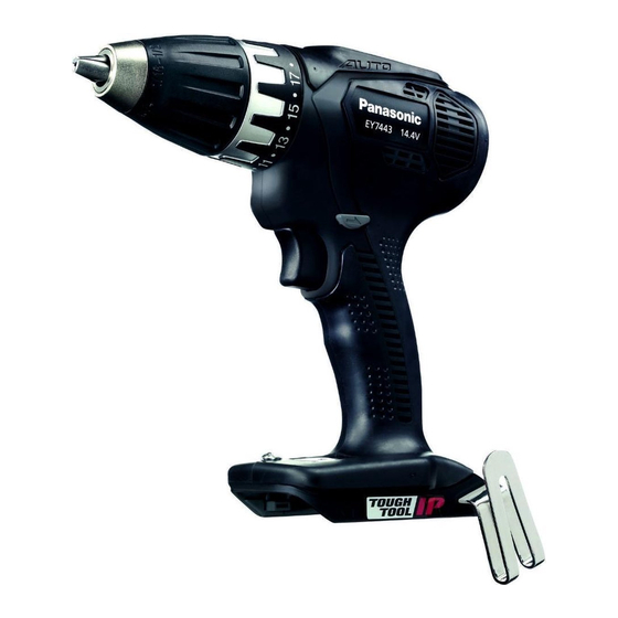
Cordless Auto Drill & Driver
Model No.
Europe
Oceania
PAGE
© Panasonic Eco Solutions Power Tools Co., Ltd.
2013. All rights reserved. Unauthorized copying and
distribution is a violation of law.
Order Number PTD1301X17CE
EY7443
PAGE
Advertisement

Related Manuals for Panasonic EY7443


Summary of Contents for Panasonic EY7443
-
Page 1: Table Of Contents
4 Disassembly and Assembly Instructions ---------------- 8 5 Wiring Connection Diagram ---------------------------------16 6 Schematic Diagram ---------------------------------------------16 7 Exploded View and Replacement Parts List -----------17 © Panasonic Eco Solutions Power Tools Co., Ltd. 2013. All rights reserved. Unauthorized copying and distribution is a violation of law. -
Page 2: Warning
1 Warning Caution: • Pb free solder has a higher melting point that standard solder; Typically the melting point is 50 - 70°F (30 - 40°C) higher. Please use a soldering iron with temperature control and adjust it to 750 ± 20°F (400 ± 10°C). In case of using high temperature solder- ing iron, please be careful not to heat too long. -
Page 3: Troubleshooting Guide
3 Troubleshooting Guide 3.1. Troubleshooting Guide... - Page 7 3.2. Trial Operation (After Checking Troubleshooting Guide) 3.2.1. Assembly • Confirm if there is no gap between housing A and B by pinching lead wires. • There is no dust or deformation on battery terminals. • Confirm if there is no dirt when repairing. 3.2.2.
-
Page 8: Disassembly And Assembly Instructions
4 Disassembly and Assembly Instructions *To assemble the tool, start with 5-12 and proceed to 5-1 *Set the clutch handle to select ''HIGH" position. 4.1. Removing the keyless chuck 4.2. Removing the plate hook... - Page 9 4.3. Removing the housing...
- Page 10 4.4. Removing the Module assembly...
- Page 11 4.5. Removing the Switch assembly 4.6. Removing the Gear Box Block and Associated Parts...
- Page 12 4.7. Removing the Carbon brush block 4.8. Removing the Transmission Assembly from the Gear Box Block...
- Page 13 4.9. Removing the motor assembly from the gear box brock 4.10. Removing the Detective module...
- Page 14 4.11. Tips for installing the Clutch Handle onto the Gear Box Block...
- Page 15 4.12. Wiring and Assembly Points...
-
Page 16: Wiring Connection Diagram
5 Wiring Connection Diagram 6 Schematic Diagram... -
Page 17: Exploded View And Replacement Parts List
7 Exploded View and Replacement Parts List Model No. : EY7443 Exploded View... - Page 18 Model No. : EY7443 Parts List Ref. Safety Part No. Part Name & Description Q'ty Remarks WEY7443H3079 HOUSING AB SET 1 (for EUROPE) WEY6450L6806 CHUCK FASTENING SCREW WEY7441K7917 KEYLESS CHUCK WEY7441H3227 CLUTCH HANDLE WEY7443L4057 GEAR BOX BLOCK WEY7441L0637 ADJUSTING SCREW...
Need help?
Do you have a question about the EY7443 and is the answer not in the manual?
Questions and answers