Panasonic EY7411 Service Manual
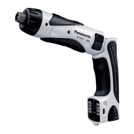
Cordless drill & driver
Hide thumbs
Also See for EY7411:
- Operating instructions manual (45 pages) ,
- Operating instructions manual (116 pages)
Table of Contents
Advertisement
TABLE OF CONTENTS
1 Warning -------------------------------------------------------------- 2
2 Specifications ----------------------------------------------------- 2
3 Troubleshooting Guide ----------------------------------------- 3
4 Disassembly and Assembly Instructions ---------------- 6
5 Wiring Connection Diagram ---------------------------------- 9
6 Schematic Diagram ---------------------------------------------- 9
7 Exploded View and Replacement Parts List -----------10
Model No. EY7411
North America
PAGE
© 2007 Matsushita Electric Works, Ltd.
All rights reserved. Unauthorized copying and distri-
bution is a violation of law.
Order Number PTD0703U32CE
Cordless Drill & Driver
F16
PAGE
Advertisement
Table of Contents

Subscribe to Our Youtube Channel
Related Manuals for Panasonic EY7411


Summary of Contents for Panasonic EY7411
-
Page 1: Table Of Contents
Order Number PTD0703U32CE Cordless Drill & Driver Model No. EY7411 North America TABLE OF CONTENTS PAGE PAGE 1 Warning -------------------------------------------------------------- 2 2 Specifications ----------------------------------------------------- 2 3 Troubleshooting Guide ----------------------------------------- 3 4 Disassembly and Assembly Instructions ---------------- 6 5 Wiring Connection Diagram ---------------------------------- 9... -
Page 2: Warning
1 Warning Caution: • Pb free solder has a higher melting point that standard solder; Typicall the melting point is 50 - 70°F (30 - 40°C) higher. Please use a soldering iron with temperature control and adjust it to 750 ± 20°F (400 ± 10°C). In case of using high temperature solder- ing iron, please be careful not to heat too long. -
Page 3: Troubleshooting Guide
3 Troubleshooting Guide... -
Page 6: Disassembly And Assembly Instructions
4 Disassembly and Assembly Instructions 4.1. Disassembly Instructions Ref. No. 1A Procedure 1A Removal of the grip. 1. Remove both sides of the grip fastening clip by sliding it outward. 2. Remove one grip fastening screw. 3. To separate the grip housing, insert the battery pack into the grip about one third. - Page 7 Procedure 1A → 1B → 1C Ref. No. 1C Removal of the motor. 1. Remove the motor and the switch block together with the torque detection PCB from the driving block. 2. Remove the switch from the motor. Ref. No. 1D Procedure 1A →...
-
Page 8: Assembly Instructions
4.2. Assembly Instructions NOTE: When reassembling, apply grease around the ring and planet gears. 4.3. After Reassembling Confirm the following pints before retuning the unit to a customer. -
Page 9: Wiring Connection Diagram
5 Wiring Connection Diagram 6 Schematic Diagram... -
Page 10: Exploded View And Replacement Parts List
7 Exploded View and Replacement Parts List 7.1. Exploded View... -
Page 11: Replacement Parts List
7.2. Replacement Parts List Safety Ref. No. Part No. Part Name & Description Quantity Remarks WEY7410K3227 CLUTCH HANDLE WEY6225L0637 ADJUSTING SCREW WEY6225L0167 CLUTCH SPRING WEY7411L0317 RUBBER SHEET (2*7.3) WEY6225L0847 CLUTCH PLATE WEY6225L0397 PIN A ( 3*15.1),(3PCS/PK) WEY7410K3717 BIT HOLDER WEY7410K1167 C-TYPE SPRING WEY7410L0867 THRUST PLATE...
Need help?
Do you have a question about the EY7411 and is the answer not in the manual?
Questions and answers