
Related Manuals for jcb AG2200


Summary of Contents for jcb AG2200
- Page 1 SAFETY AND OPERATING MANUAL ANGLE GRINDER JCB-AG2200 ORIGINAL INstRuCtIONs SO53 3LE Customer Helpline 0845 600 5526...
-
Page 3: General Power Tool Safety Warnings
GENERAL POwER tOOL sAfEty wARNINGs wARNING! Read all safety There is an increased risk of warnings and all instructions. electric shock if your body is Failure to follow the warnings and grounded. instructions may result in electric c) Do not expose power tools shock, fire and/or serious injury. - Page 4 safety shoes, hard hat, or hearing use the correct power tool for protection used for appropriate your application. The correct conditions will reduce personal power tool will do the job better injuries. and safer at the rate for which it c) Prevent unintentional starting.
- Page 5 to control. g) use the power tool, accessories and tool bits etc. in accordance with these instructions, taking into account the working conditions and the work to be performed. Use of the power tool for operations different from those intended could result in a hazardous situation.
- Page 6 ADDItIONAL sAfEty POINts fOR yOuR ANGLE GRINDER safety warnings Common for flanges, backing pads or any Grinding or Abrasive Cutting-Off other accessory must properly Operations: fit the spindle of the power tool. a) this power tool is intended to Accessories with arbour holes function as a grinder, or cut-off that do not match the mounting tool.
- Page 7 be capable of filtrating particles into your body. generated by your operation. n) Regularly clean the power tool’s Prolonged exposure to high air vents. The motor’s fan will intensity noise may cause hearing draw the dust inside the housing loss. and excessive accumulation i) Keep bystanders a safe distance of powdered metal may cause...
- Page 8 or bouncing have a tendency to that is entering into the pinch snag the rotating accessory and point can dig into the surface of cause loss of control or kickback. the material causing the disc to e) Do not attach a saw chain climb out or kick out.
- Page 9 flanges that are of correct size disc comes to a complete stop. and shape for your selected disc. Never attempt to remove the cut- Proper disc flanges support the off disc from the cut while the disc disc thus reducing the possibility is in motion otherwise kickback of disc breakage.
- Page 10 syMBOLs To reduce the risk of injury, user must read instruction manual Warning Double insulation Wear ear protection Wear eye protection Wear dust mask Waste electrical products must not be disposed of with household waste. Please recycle where facilities exist. Check with your local authorities or retailer for recycling advice SO53 3LE...
-
Page 11: Component List
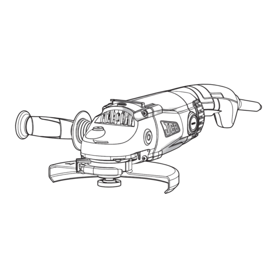
COMPONENt LIst 1. LOCK-Off & LOCK-ON swItCH 2. HAND GRIP AREA 3. ANtI-vIBRAtION AuxILIARy HANDLE 4. sPINDLE LOCK ButtON 5. OutER fLANGE 6. INNER fLANGE 7. sPINDLE 8. DIsC * 9. sPANNER 10.PROtECtION GuARD fOR GRINDING 11.CLAMPING sCREw 12.RAIsED PROJECtION 13.PROtECtION GuARD fOR CuttING * 14.INsuLAtING tIP (see 7 ) 15.CARBON BRusH (see 7 ) -
Page 12: Technical Data
tECHNICAL DAtA Voltage 230-240V~50Hz Power input 2200W Rated speed 6500/min Protection class Spindle thread Disc size 230mm Disc bore 22.2mm Machine weight 4.7kg NOIsE INfORMAtION A weighted sound pressure L :98.5dB (A) A weighted sound power L :109.5dB (A) & K = 3.0dB (A) Wear ear protection when sound pressure is over: 80dB (A) vIBRAtION INfORMAtION... - Page 13 this tool may cause hand-arm vibration syndrome if its use is not adequately managed. wARNING: To be accurate, an estimation of exposure level in the actual conditions of use should also take account of all parts of the operating cycle such as the times when the tool is switched off and when it is running idle but not actually doing the job.
-
Page 14: Intended Use
INtENDED usE NOtE: Before using the tool, read the the safety and operating manual carefully. INtENDED usE The machine is intended for cutting, roughing and brushing metal and stone materials without using water. For cutting metal, a special protection guard for cutting (accessory) must be used. - Page 15 touch until they have cooled. 1. sPINDLE LOCK ButtON Clean the grinder spindle and all parts to be mounted. For clamping and loosening the grinding tools, lock the grinder spindle (7) with the spindle lock button (4). Actuate the spindle lock button (4) only when the grinder spindle is at a standstill! 2.
- Page 16 grinding discs the raised part of the outer flange is fitted facing towards the disc to provide improved support for the disc hole (See 4 ). Always ensure your disc is securely clamped. ADJustING tHE PROtECtION GuARD Before any work on the machine itself, pull the mains plug.
-
Page 17: Starting Operation
OPERAtION stARtING OPERAtION Your switch is locked off to prevent accidental starting. To switch on your tool, push the safety switch lever (B) forward and depress on/ off switch (A) fully. Now your tool is switched on. To switch off your tool, just release the On/Off switch. - Page 18 OPERAtING INstRuCtIONs ● Clamp the workpiece if it does not remain stationary due to its own weight. ● Do not strain the machine so heavily that it comes to a standstill. ● Grinding and cutting discs become very hot while working; do not touch until they have cooled.
- Page 19 guard for cutting. When cutting, do not press, tilt or oscillate the machine. Work with moderate feed, adapted to the material being cut. Do not reduce the speed of running down cutting discs by applying sideward pressure. The direction in which the cutting is performed is important.
- Page 20 REPLACE tHE CARBON BRusH As fOLLOws: (see & Unscrew the brush cap (17), remove the carbon brush (15), if the carbon has worn down to 6mm it should be replaced. Always replace both brushes at the same time, insert the new brush and replace the brush cap.
-
Page 21: Working Hints For Your Angle Grinder
wORKING HINts fOR yOuR ANGLE GRINDER If your angle grinder becomes too hot, run no load for 2-3 minutes to cool the motor. Never start your angle grinder with the disc/ accessory in contact with the workpiece. Always start at no load to achieve maximum speed then start working. Do not force the disc to work faster, reducing the Disc’s moving speed means longer working time. -
Page 22: Plug Replacement (Uk & Ireland Only)
PLuG REPLACEMENt (uK & IRELAND ONLy) If you need to replace the fitted plug then follow the instructions below. IMPORtANt The wires in the mains lead are colored in accordance with the following code: Blue – Neutral Brown – Live As the colors of the wires in the mains lead of this appliance may not correspond with the coloured markings identifying the terminals in your plug, proceed as follows. -
Page 23: Warranty Statement
In 1945 JCB began producing construction equipment. Today, we build the world’s number one diggers, each one the product of our unswerving focus on innovation, quality and engineering. JCB power tools are built to give you the same world beating standards of performance. The same innovation, to always get the job done better, the same quality, to never let you down, the same engineering heritage and expertise that you can trust 100%. -
Page 24: Ec Declaration Of Conformity
EC DECLARAtION Of CONfORMIty Positec Power tools RG24 8AL, uK Declare that the product Description JCB Angle Grinder Type (JCB-AG2200) Function Peripheral and lateral grinding Complies with the following Directives, EC Machinery Directive 2006/42/EC EC Low Voltage Directive 2006/95/EC EC Electromagnetic Compatibility Directive...
Need help?
Do you have a question about the AG2200 and is the answer not in the manual?
Questions and answers