Yamaha RX-V365 Service Manual
Hide thumbs
Also See for RX-V365:
- Owner's manual (104 pages) ,
- Specifications (2 pages) ,
- Connection manual (2 pages)
Table of Contents
Advertisement
RX-V365/HTR-6230
This manual has been provided for the use of authorized YAMAHA Retailers and their service personnel.
It has been assumed that basic service procedures inherent to the industry, and more specifi cally YAMAHA Products, are already known
and understood by the users, and have therefore not been restated.
WARNING:
IMPORTANT:
The data provided is believed to be accurate and applicable to the unit(s) indicated on the cover. The research, engineering, and service
departments of YAMAHA are continually striving to improve YAMAHA products. Modifications are, therefore, inevitable and
specifi cations are subject to change without notice or obligation to retrofi t. Should any discrepancy appear to exist, please contact the
distributor's Service Division.
WARNING:
IMPORTANT:
■ CONTENTS
To Service Personnel ............................................2
Front Panels .........................................................3–4
Rear Panels ...........................................................5–8
Remote Control Panels .......................................9
Specifications ................................................... 10–14
Internal View .......................................................... 15
Disassembly Procedures ............................. 16–18
Updating Firmware .......................................... 19–21
Self-Diagnostic Function ...........................22–38
Display Data .......................................................39–40
1 0 1 1 3 1
SERVICE MANUAL
IMPORTANT NOTICE
Failure to follow appropriate service and safety procedures when servicing this product may result in personal injury,
destruction of expensive components, and failure of the product to perform as specifi ed. For these reasons, we advise
all YAMAHA product owners that any service required should be performed by an authorized YAMAHA Retailer or
the appointed service representative.
The presentation or sale of this manual to any individual or fi rm does not constitute authorization, certifi cation or
recognition of any applicable technical capabilities, or establish a principle-agent relationship of any form.
Static discharges can destroy expensive components. Discharge any static electricity your body may have
accumulated by grounding yourself to the ground buss in the unit (heavy gauge black wires connect to this buss).
Turn the unit OFF during disassembly and part replacement. Recheck all work before you apply power to the unit.
Ic Data ...................................................................41–55
Block DiagramS ................................................56–57
Printed Circuit Boards .................................58–71
Pin Connection Diagrams ...................................72
Schematic DiagramS .......................................73–83
Replacement Parts List ................................85–95
Remote Control ...............................................96–98
Advanced Setup ......................................................99
Copyright © 2009
This manual is copyrighted by YAMAHA and may not be copied or
redistributed either in print or electronically without permission.
AV RECEIVER
All rights reserved.
P.O.Box 1, Hamamatsu, Japan
animate '09.02
Advertisement
Table of Contents

Related Manuals for Yamaha RX-V365


Summary of Contents for Yamaha RX-V365
-
Page 1: Important Notice
This manual has been provided for the use of authorized YAMAHA Retailers and their service personnel. It has been assumed that basic service procedures inherent to the industry, and more specifi cally YAMAHA Products, are already known and understood by the users, and have therefore not been restated. -
Page 2: To Service Personnel
RX-V365/HTR-6230 ■ TO SERVICE PERSONNEL AC LEAKAGE 1. Critical Components Information WALL EQUIPMENT TESTER OR Components having special characteristics are marked OUTLET UNDER TEST EQUIVALENT must be replaced with parts having specifications equal to those originally installed. 2. Leakage Current Measurement (For 120V Models Only) -
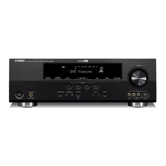
Page 3: Front Panels
RX-V365/HTR-6230 ■ FRONT PANELS Top view Front view RX-V365 (U, C models) RX-V365 (T model) RX-V365 (R, K, A, B, G, E, F, L models) - Page 4 RX-V365/HTR-6230 HTR-6230 (U, C models) HTR-6230 (T model) HTR-6230 (R, K, G, E, F models)
-
Page 5: Rear Panels
RX-V365/HTR-6230 ■ REAR PANELS RX-V365 (U, C models) RX-V365 (R model) Nameplate RX-V365 (T model) - Page 6 RX-V365/HTR-6230 RX-V365 (K model) RX-V365 (A model) RX-V365 (B, G, E, F models)
- Page 7 RX-V365/HTR-6230 RX-V365 (L model) HTR-6230 (U, C models) HTR-6230 (R model)
- Page 8 RX-V365/HTR-6230 HTR-6230 (T model) HTR-6230 (K model) HTR-6230 (G, E, F models)
-
Page 9: Remote Control Panels
RX-V365/HTR-6230 ■ REMOTE CONTROL PANELS RAV283 RAV284 RAV34 (U, C models) (R, T, K, A, L models) (B, G, E, F models) T model... -
Page 10: Specifications
RX-V365/HTR-6230 ■ SPECIFICATIONS ■ Audio Section Tone Control Characteristics Minimum RMS Output Power (Power Amp. Section) BASS (1 kHz, 0.9 % THD) Boost/Cut ..........±10 dB (100 Hz) FRONT L/R, CENTER, SURROUND L/R TREBLE U, C models (8 ohms) ......... 100 W/ch Boost/Cut ..........±10 dB (20 kHz) - Page 11 Maximum Power Consumption (5 ch drive, 10 % THD) R, L models ..............530 W “SILENT CINEMA” is a trademark of Yamaha Corporation. Dimensions (W x H x D) ....435 x 151 x 317.6 mm (17-1/8" x 5-7/8" x 12-1/2") Weight ............
- Page 12 RX-V365/HTR-6230 • SCENE TEMPLATE Program NIGHT Select (Default) R, T, K, A, B, G, SCENE name Contents Source Mode Sub-mode Mode U, C models E, F, L models DVD Viewing STRAIGHT – SYSTEM O (SCENE 1) Movie DVD Movie Viewing...
- Page 13 RX-V365/HTR-6230 • SET MENU TABLE CATEGORY MAIN MENU SUB MENU SELECT MENU VALUE [INITIAL] BASIC SETUP ROOM S / [M] / L (U, C, T models) SUBWOOFER : YES [YES] / NONE SPEAKERS : 5 spk 2 spk / 3 spk / 4 spk / [5 spk]...
- Page 14 RX-V365/HTR-6230 CATEGORY MAIN MENU SUB MENU SELECT MENU VALUE [INITIAL] 2 INPUT A) INPUT ASSIGN IN (1) [COAXIAL] : DVD CD / MD/CD-R / [DVD] / DTV/CBL / V-AUX / DVR MENU IN (2) [OPTICAL] : DTV/CBL CD / MD/CD-R / DVD / [DTV/CBL] / V-AUX / DVR...
-
Page 15: Internal View
RX-V365/HTR-6230 ■ INTERNAL VIEW POWER TRANSFORMER OPERATION (3) P.C.B. OPERATION (5) P.C.B. (R, L models) MAIN (3) P.C.B. AM/FM TUNER HDMI P.C.B. OPERATION (4) P.C.B. DSP P.C.B. MAIN (4) P.C.B. MAIN (1) P.C.B. OPERATION (2) P.C.B. OPERATION (11) P.C.B. OPERATION (10) P.C.B. -
Page 16: Disassembly Procedures
RX-V365/HTR-6230 ■ DISASSEMBLY PROCEDURES (Remove parts in the order as numbered.) Disconnect the power cable from the AC outlet. 1. Removal of Top Cover a. Remove 4 screws ( ), 4 screws ( ) and screw ( ). (Fig. 1) b. - Page 17 RX-V365/HTR-6230 3. Removal of HDMI P.C.B. a. Remove CB904 and CB905. (Fig. 2) b. Remove 5 screws ( ). (Fig. 3) c. Remove the HDMI P.C.B.. (Fig. 2) 4. Removal of OPERATION (4) P.C.B. a. Remove CB181–182 and CB193. (Fig. 2) b.
-
Page 18: B. Remove 3 Screws
RX-V365/HTR-6230 When checking the P.C.B. a. Remove the top cover. (Fig. 1) b. Remove 3 screws ( ). (Fig. 3) c. Remove 5 screws ( ) and 4 screws ( ). (Fig. 4) d. Place the P.C.B.s (with rear panel) upright. (Fig. 5) e. -
Page 19: Updating Firmware
RX-V365/HTR-6230 ■ UPDATING FIRMWARE After replacing the following parts, be sure to write the latest firmware. • DSP P.C.B. • IC201 (DSP P.C.B.) ● Required tools • DVD or CD player (with DIGITAL OUTPUT (OPTICAL or COAXIAL) jack) • Optical cable (when OPTICAL jack is used) •... - Page 20 RX-V365/HTR-6230 ● Confirmation of firmware version and checksum Before and after writing the firmware, check the firmware version and checksum value by using the self-diagnostic function menu “14. ROM VER/SUM”. For more information, refer to “SELF-DIAGNOSTIC FUNCTION”. Have the firmware version and checksum displayed by using sub-menu, and note down them.
-
Page 21: Rx-V365/Htr
RX-V365/HTR-6230 When the version of the firmware to be written is the same as the one existing in this unit, “Same Version”, “Please...” and “Turn off!!” are displayed repeatedly. (Upgrading is not necessary.) If the display remains unchanged for longer than 10 seconds after starting the firmware CD play procedure, perform the firmware CD play procedure again from the beginning. - Page 22 RX-V365/HTR-6230 ■ SELF-DIAGNOSTIC FUNCTION This unit has self-diagnostic functions that are intended for inspection, measurement and location of faulty point. There are 14 main menu items, each of which has sub-menu items. Listed in the table below are menu items and sub-menu items.
- Page 23 RX-V365/HTR-6230 Main menu Sub-menu AD DATA CHECK PD : xxx PV : xxx TH : xxx PL : xxx PI : xxx DE : xxx K0 : xxx K1 : xxx PROTECTION HISTORY History 1 History 2 History 3 History 4...
- Page 24 RX-V365/HTR-6230 ● Starting Self-Diagnostic Function While pressing those 2 keys of this unit as shown in the figure below, press the “STANDBY/ON” key to turn on the power. Keys of this unit While pressing these keys, turn on the power.
- Page 25 RX-V365/HTR-6230 When there is no history of protection function: Opening message Main menu display When there is no protection history After a few seconds When there is a history of protection function due to excess current: AD value when the protection function is working Cause: An excessive current flowed through the power amplifier.
- Page 26 RX-V365/HTR-6230 When there is a history of protection function due to abnormal voltage in the power supply section AD value when the protection function is working Cause: The voltage in the power supply section is abnormal. Supplementary information: The protection function worked due to a defect or overload in the power supply.
- Page 27 RX-V365/HTR-6230 ● Operation procedure of Main menu and Sub-menu There are 14 menu items, each of them having sub-menu items. Main menu selection: Select the menu using “>” (forward) and “<” (reverse) keys of PROGRAM. Sub-menu selection: Select the sub-menu using “SCENE 2” (forward) and “SCENE 1” (Reverse) keys.
- Page 28 RX-V365/HTR-6230 ● Details of Self-Diagnostic Function menu BYPASS Using the sub-menu, it is possible to select ANALOG BYPASS output or DSP BYPASS output. ANALOG BYPASS The analog input audio signal is output to FRONT L/R with EFFECT OFF. INPUT: DVD ANALOG...
- Page 29 RX-V365/HTR-6230 SPEAKER SET The analog switch settings for each sub-menu are as shown in the table below. FRONT CENTER SURROUND SUBWOOFER FRONT : SML 0dB SMALL LARGE LARGE SWFR CENTER : NONE LARGE NONE LARGE SWFR LFE/B : FRNT LARGE...
- Page 30 RX-V365/HTR-6230 6CH INPUT The input source [MULTI CHANNEL INPUT] is selected. It is possible to select the 6-ohm/8-ohm by using the sub-menu. 6 ch INPUT 6-ohm INPUT: MULTI CH INPUT SPEAKER OUT: 1 kHz, SUBWOOFER OUTPUT: 50 Hz SPEAKER OUT...
- Page 31 RX-V365/HTR-6230 FL CHECK This menu is used to check the FL display section. The audio signal is processed using STRAIGHT. Checking FL display section Initial display All segments OFF All segments ON (dimmer 100%) All segments ON (dimmer 50%) Lighting of segments in lattice...
- Page 32 RX-V365/HTR-6230 TEST TONE The noise generator with a built-in DSP outputs the test noise through the channels specified by the sub-menu. The noise frequency for LFE (SUBWOOFER) is 35 to 80 Hz. Other than that, the noise frequency is 500 to 2 kHz.
- Page 33 RX-V365/HTR-6230 PROTECTION The A/D setting value of each protection is displayed. (Reference voltage: 3.3 V=255) PRD (Amplifier DC protection) Low The minimum preset value of PRD is displayed. PRD (Amplifier DC protection) High The maximum preset value of PRD is displayed.
- Page 34 RX-V365/HTR-6230 A/D DATA CHECK This menu is used to display the A/D conversion value of the microprocessor which detects panel keys of this unit and protection functions by using the sub-menu. When K0/K1 menu is selected, keys become non-operable due to detection of the values of all keys.
- Page 35 RX-V365/HTR-6230 K0/K1 K0/K1: KEY0/KEY1 (Panel key of this unit) When the A/D conversion value of the panel key becomes out of the specified range (standard value ±4), normal operation will not be available. In that case, check the constant of partial pressure resistor, solder condition, etc. with referring to the table below.
- Page 36 RX-V365/HTR-6230 11. DOCK (U, C models) DOCK check This menu is used to check the DOCK connector without the iPod itself. With the power to this unit turned off, short between pins No. 14 (TX) and No. 18 (RX), between pins No. 1 (PWR) and No.
- Page 37 RX-V365/HTR-6230 Clear Bluetooth pairing information While the Bluetooth DOCK is connected, initialization of the Bluetooth DOCK pairing information is inhibited/reserved. Use “PRESET/TUNING<” and “PRESET TUNING>” keys for operation. Initialization inhibited Initialization inhibited User memory initialization is not executed. Select this sub-menu to protect the user memory.
- Page 38 RX-V365/HTR-6230 14. ROM VER/SUM The firmware version and checksum values are displayed. The checksum is obtained by adding the data at every 8 bits for each program area and expressing the result as a 4 figure hexadecimal data. Version Firmware version of microprocessor (IC101 DSP P.C.B.) is displayed.
-
Page 39: Display Data
RX-V365/HTR-6230 ■ DISPLAY DATA ● V2001 : 17-BT-29GNK (OPERATION P.C.B.) PATTERN AREA ● PIN CONNECTION Pin No. 68 67 Connection F2 NX Pin No. Connection Note : 1) F1, F2 ..Filament pin 2) NP ..No pin 3) NX ..No extend pin 4) 1G-17G .. - Page 40 RX-V365/HTR-6230 ● ANODE CONNECTION 13G-1G – – – – – – – – – –...
- Page 41 RX-V365/HTR-6230 ■ IC DATA IC101: ADSP-BF531 CPU (DSP P.C.B.) Microprocessor and DSP Event controller/ JTAG test Watch dock timer and emulation Core timer Real time clock Voltage regulator UART port IrDA® Memory L1 order L1 data management memory memory unit...
- Page 42 RX-V365/HTR-6230 Pin No. Port Name Function Name Detail of Function DGND – Ground of external DGND – Ground of external DGND – Ground of external /VINTSW VROUT2 Voltage regulator drive for Q101 /VINTSW VROUT1 Voltage regulator drive for Q101 VDDEXT VDDEXT –...
- Page 43 RX-V365/HTR-6230 Pin No. Port Name Function Name Detail of Function TSCLK1 TSCLK1 Serial port 1, serial transmission clock DR1SEC DR1SEC Serial port 1, secondary reception data DR1PRI DR1PRI Serial port 1, primary reception data RFS1 RFS1 Serial port 1, frame synchronization reception...
- Page 44 RX-V365/HTR-6230 Pin No. Port Name Function Name Detail of Function ADDR19 SDRAM address bus 19 ADDR18 SDRAM address bus 18 ADDR17 SDRAM address bus 17 ADDR16 SDRAM address bus 16 ADDR15 SDRAM address bus 15 ADDR14 SDRAM address bus 14...
- Page 45 RX-V365/HTR-6230 • Microprocessor extended port IC204-IC206: SN74LV573APWR (DSP P.C.B.) Octal 3-state D-latches with 3-state outputs IC204 Pin No. Port Name Function Name Detail of Function /EXPE Extended port enable Data bus 00 Data bus 01 Data bus 02 Data bus 03...
- Page 46 RX-V365/HTR-6230 IC206 Pin No. Port Name Function Name Detail of Function /EXPE Extended port enable Data bus 00 Data bus 01 Data bus 02 Data bus 03 Data bus 04 Data bus 05 Data bus 06 Data bus 07 DGND...
- Page 47 RX-V365/HTR-6230 • Microprocessor ADC select port IC401: ADC084S021CIMM (DSP P.C.B.) 4-channel, 200 kSPS, 8-bit A/D converter 8-Bit SCLK SUCCESSIVE APPROXIMATION DOUT ADC084S021 SCLK CONTROL LOGIC DOUT Pin No. Port Name Function Name Detail of Function /SPISEL1 CS for microprocessor +3.3S...
- Page 48 RX-V365/HTR-6230 IC402 Pin No. Port Name Function Name Detail of Function – – SPI bus IN4 (IC401) LINKACTIVE Link detect (U, C models) XM_MUTE DGND (Pull-down) DGND Ground of external DGND Ground of external ADSEL2 Input select 2 ADSEL1 Input select 1...
- Page 49 RX-V365/HTR-6230 IC301: AK4588VQ (DSP P.C.B.) 2/8-channel audio CODEC with DIR PVSS PVDD X'tal Clock Oscillator 8 to 3 Recovery Clock MCKO1 Generator Input MCKO2 Selector LRCK2 DAIF Audio BICK2 Decoder SDTO2 DAUX2 AVDD AVSS DVDD Error & Q-subcode CCLK DVSS...
- Page 50 RX-V365/HTR-6230 Pin No. Function Name Detail of Function INT1 Interrupt 1 pin BOUT Block-start output pin for receiver input “H” during first 40 flames TVDD – Output buffer power supply pin, 2.7 V to 5.5 V DVDD – Digital power supply pin, 4.5 V to 5.5 V DVSS –...
- Page 51 RX-V365/HTR-6230 Pin No. Function Name Detail of Function ROUT3 DAC3 R ch analog output pin No connect pin – No internal bonding / This pin should be opened LOUT2 DAC2 L ch analog output pin No connect pin – No internal bonding / This pin should be opened...
- Page 52 RX-V365/HTR-6230 IC161: R2A15218FP (MAIN P.C.B.) 8-channel electronic volume with 11 input selector and tone control 49 48 46 45 38 37 34 33 A VCC A VCC MUTE N.C. A VEE A VEE N.C. TREL 0/-6/-12/-18dB ADCL BASSL2 BASSL1 ADCR N.C.
- Page 53 RX-V365/HTR-6230 Pin No Function Name Detail of Function N.C. No connected SBLC L/R/C/SW/SL/SR/SBL/SBR ch terminal to connect capacitor to reduce noise from changing the volume SBLOUT FL/FR/C/SW/SL/SR/SBL/SBR ch output terminal AGND Analog GND terminal SBROUT FL/FR/C/SW/SL/SR/SBL/SBR ch output terminal SBRC...
- Page 54 RX-V365/HTR-6230 Pin No Function Name Detail of Function AGND Analog GND terminal N.C. No connected INR1 L/R ch input terminal (input selector) INL1 L/R ch input terminal (input selector) INR2 L/R ch input terminal (input selector) INL2 L/R ch input terminal (input selector)
- Page 55 RX-V365/HTR-6230 IC201: M66003-0131FP-R (OPERATION P.C.B.) Pin No Port Name Function Name Detail of Function 18 digit 5x7 segment VFD controller/driver SEG32 Segment output SEG31 Segment output SEG30 Segment output Positive power supply for DIG and SEG outputs SEG29 Segment output...
- Page 56 RX-V365/HTR-6230 ■ BLOCK DIAGRAMS VIDEO, AUDIO and Power Supply Sections BLOCK DIAGRAM → OPERATION → → OPERATION DTV/CBL & POWER TRANSFORMER MONITOR OUT AC IN DTV/CBL V-AUX & DVR IN MONITOR OUT DVR OUT → HDMI → SUB TRANSFORMER DTV/CBL...
- Page 57 RX-V365/HTR-6230 Control Section BLOCK DIAGRAM → OPERATION → OPERATION → OPERATION → MAIN → → OPERATION...
- Page 58 RX-V365/HTR-6230 ■ PRINTED CIRCUIT BOARDS POINT C / EX3.3, D / Pin 8 of IC505, E / J504 EX3.3 EX3.3 DSP P.C.B. (Side A) IC505 8 pin IC505 8 pin (/DRESET) (/DRESET) J504 J504 MAIN (1) (/RESET) (/RESET) (CB161) OPERATION (4)
- Page 59 RX-V365/HTR-6230 DSP P.C.B. (Side B) R, K, A, B, G, E, F, L models U, C models R, T, K, A, B, G, E, F, L models U, C models R, T, K, A, B, G, E, F, L models •...
- Page 60 RX-V365/HTR-6230 OPERATION (1) P.C.B. (Side A) MAIN (4) (CB191) R, K, A, B, G, E, F, L models OPERATION (2) R, K, A, B, G, E, F, L models (CB235) (CB408) W2001 /MICDET REM1 /BLK CKFD DTFD /CEFD ADKEY1 ADKEY0 +3.3S...
- Page 61 RX-V365/HTR-6230 OPERATION (1) P.C.B. (Side B) R, K, A, B, G, E, F, L models IC202 • Semiconductor Location Ref No. Location D2002 D2004 D2006 D2008 D2009 IC201 IC202 Q2001 Q2002 Q2003 Q2004 Q2005...
- Page 62 RX-V365/HTR-6230 OPERATION (2) P.C.B. (Side A) U, C models IC236 IC237 IC232 IC233 IC234 IC239 IC238 OPERATION (1) (CB203) (CB516) XMPWR /PDET /RESET U, C models W2154 +3.3 +5XM CB233 CB234 POWER TRANSFORMER OPERATION (3) MAIN (1) HDMI (CB905) (CB251) (CB103) •...
- Page 63 RX-V365/HTR-6230 OPERATION (2) P.C.B. (Side B) U, C models U, C models R, T, K, A, B, G, E, F, L models U, C models • Semiconductor Location Ref No. Location Ref No. Location D2151 D2167 D2154 D2168 D2156 D2170...
- Page 64 RX-V365/HTR-6230 OPERATION (3) P.C.B. OPERATION (3) P.C.B. (Side A) (Side B) U, C, T, K, A, B, G, E, F models R, L models CB254 CB252 CB257 OPERATION (2) (CB231) POWER TRANSFORMER ACDET R, L models R, L models R, L models...
- Page 65 RX-V365/HTR-6230 OPERATION (4) P.C.B. OPERATION (4) P.C.B. (Side A) (Side B) U, C models HDMI (CB904) /VIB /VIA • Semiconductor Location Ref No. Location D181 IC181 MAIN (4) IC183 (CB193) Q181 Q182 V-AUX Q183 Q184 MAIN (1) (W161) R, T, K, A, B, G, E, F, L models...
- Page 66 RX-V365/HTR-6230 OPERATION (5) P.C.B. (Side A) OPERATION (5) P.C.B. (Side B) R, L models VOLTAGE SELECTOR CB258 CB258 POWER TRANSFORMER • Semiconductor Location Ref No. Location D2301 D2302 OPERATION (6) P.C.B. OPERATION (6) P.C.B. (Side A) (Side B) D2303 MAIN (1)
- Page 67 RX-V365/HTR-6230 OPERATION (7) P.C.B. OPERATION (7) P.C.B. (Side A) (Side B) JK266 W2351 MAIN (4) VIDEO PORTABLE (CB192) AUDIO VIDEO AUX • Semiconductor Location Ref No. Location D2351 D2352 D2353 OPERATION (10) P.C.B. (Side A) OPERATION (11) P.C.B. (Side A)
- Page 68 RX-V365/HTR-6230 SPEAKERS MAIN (1) P.C.B. (Side A) FRONT A + / - + / - MULTI CH INPUT AUDIO PREOUT MAIN (3) FRONT SURROUND CENTER / DTV/CBL MD/CD-R (W101B) SUBWOOFER WOOFER (PLAY) (REC) L / R L / R L / R...
- Page 69 RX-V365/HTR-6230 MAIN (1) P.C.B. (Side B) • Semiconductor Location B, G, E, F models Ref No. Location D103 D104 D107 IC164 D161 D162 D163 IC163 IC161 IC162 IC163 IC164 IC168 IC169 IC162 Q101 Q102 Q103 Q104 30 31 IC168 Q105...
- Page 70 RX-V365/HTR-6230 MAIN (3) P.C.B. (Side A) MAIN (3) P.C.B. (Side B) SPEAKERS SURROUND CENTER FRONT B + / - + / - + / - + / - + / - W102B W101B MAIN (1) (W102A) MAIN (1) (W101A) MAIN (4) P.C.B.
- Page 71 RX-V365/HTR-6230 HDMI P.C.B. (Side A) HDMI P.C.B. (Side B) • Semiconductor Location Ref No. Location D4909 D4910 HDMI D4911 DTV/CBL D4912 D4913 D4914 CB903 CB902 CB901 D4915 D4916 D4917 D4918 D4919 D4920 D4921 IC902 IC901 D4922 D4923 D4924 D4925 IC903...
- Page 72 RX-V365/HTR-6230 ■ PIN CONNECTION DIAGRAMS • ICs • Diodes 1SS133, 176 1SS355 KDS160-RTK KBP103G 1.0A 200V ADC084S021 CIMM ADSP-BF531 CPU AK4588VQ BR25L320F-W EEPROM RB500V-40 1SS270A RB501V-40 MTZJ4.7A MTZJ33B Anode Anode Anode – Cathode Cathode Cathode MA8075-H RB160L-40 TE25 TS6P03G 6.0A 200V MA8100-H UDZ5.1B...
- Page 73 RX-V365/HTR-6230 SCHEMATIC DIAGRAMS DSP 1/6 to DSP 2/6 EEPROM to DSP 5/6 MICROPROCESSOR to DSP 2/6 to DSP 5/6 to DSP 6/6 IC101 to DSP 3/6 to DSP 5/6 to DSP 4/6 to DSP 6/6 to DSP 2/6 to DSP 5/6...
- Page 74 RX-V365/HTR-6230 DSP 2/6 to DSP 1/6 IC203 SDRAM IC203 to DSP 5/6 EXTENDED PORT to DSP 1/6 IC202: K4S641632K-UC60000 64 M synchronous DRAM to DSP 5/6 Data Input Register LDQM Bank Select 2M x 8 / 1M x16 to DSP 4/6...
- Page 75 RX-V365/HTR-6230 DSP 3/6 IC301: AK4588VQ 2/8-channel audio CODEC with DIR PVSS PVDD X'tal Clock Oscillator 8 to 3 Recovery Clock MCKO1 Generator Input MCKO2 Selector LRCK2 DAIF Audio BICK2 Decoder SDTO2 DAUX2 AVDD AVSS DVDD Error & DVSS AC-3/MPEG Q-subcode...
- Page 76 RX-V365/HTR-6230 DSP 4/6 to DSP 2/6 * Destination for A/D port R406 [ohm] 1.5 k 3.3 k 4.7 k 6.8 k 8.2 k R407 [ohm] 8.2 k 6.8 k 5.6 k 3.9 k 2.2 k DEST (1 pin) [V] 2.6-3.0 2.0-2.4...
- Page 77 RX-V365/HTR-6230 DSP 5/6 CB512 to DSP 1/6 to DSP 2/6 to DSP 2/6 to DSP 1/6, 2/6, 4/6 Page 82 to MAIN (1)_CB161 CB501 to DSP 1/6-4/6 Page 81 to MAIN (1)_CB101 CB502 to DSP 3/6 to DSP 3/6 to DSP 3/6...
- Page 78 RX-V365/HTR-6230 DSP 6/6 (U, C models) to DSP 1/6 to DSP 1/6 to DSP 4/6 to DSP 1/6 to DSP 5/6 to DSP 5/6 to DSP 2/6 B, G, E, F models to DSP 5/6 to DSP 5/6 to DSP 5/6...
- Page 79 RX-V365/HTR-6230 OPERATION 1/2 IC202: NJM4565M IC201: M66003-0131FP-R Dual operational amplifier 18 digit 5 x 7 segment VFD controller/driver Display code CGROM SEG00 (8-bit x 60) (35 bit x 166) Segment SEG25 Code output write SEG26 circuit CGROM 2, 6 Serial...
- Page 80 RX-V365/HTR-6230 OPERATION 2/2 COMPONENT VIDEO VIDEO MONITOR OUT DTV/CBL -4.8 Page 82 to MAIN (4)_CB193 W181 IC181 CB182 SELECTOR VIDEO AMP Page 77 to DSP_CB504 -4.9 (U, C models) -5.6 -5.5 -11.1 OPERATION (4) Page 82 Page 83 OPERATION (5)
- Page 81 RX-V365/HTR-6230 MAIN 1/2 POWER AMPLIFIER IC102 5.16 FRONT L 51.8 SURROUND L SPEAKERS FRONT A -11.9 51.6 -11.9 W101A -12.0 51.6 to MAIN 2/2 W103 MAIN (3) -12.0 POWER AMPLIFIER W101B IC101 FRONT B SURROUND L CB101 CENTER CENTER SPEAKERS...
- Page 82 RX-V365/HTR-6230 MAIN 2/2 FRONT IC161: R2A15218FP 8-channel electronic volume with 11 input selector and tone control 49 48 46 45 38 37 34 33 A VCC MUTE A VCC SURROUND A VEE N.C. MULTI CH A VEE INPUT N.C. TREL...
- Page 83 RX-V365/HTR-6230 HDMI HDMI DTV/CBL CB901 CB903 CB903 IC901 IC902 IC907 IC903 IC908 CB904 Page 80 to OPERATION (4)_W182 IC908 CB905 Page 80 to OPERATION (2)_W2154 IC905 IC904 IC901: PCA9517DP IC903: CXB1442AR-T4 Level translating I C-bus repeater Cable equalizer with 2-system switching function...
-
Page 84: Replacement Parts List
RX-V365/HTR-6230 ■ REPLACEMENT PARTS LIST • ELECTRICAL COMPONENT PARTS WARNING ● Components having special characteristics are marked and must be replaced with parts having specifications equal to those originally installed. ABBREVIATIONS IN THIS LIST ARE AS FOLLOWS: C.A.EL.CHP : CHIP ALUMI.ELECTROLYTIC CAP L.EMIT... - Page 85 RX-V365/HTR-6230 P.C.B. DSP P.C.B. DSP Ref No. Part No. Description Markets Ref No. Part No. Description Markets WN242100 P.C.B. C502 UR838220 C.EL 220uF WN242200 P.C.B. C503-504 US062100 C.CE.CHP 100pF 50V B WN242300 P.C.B. C513-515 US062100 C.CE.CHP 100pF 50V B WN242400 P.C.B.
- Page 86 RX-V365/HTR-6230 P.C.B. OPERATION P.C.B. OPERATION Ref No. Part No. Description Markets Ref No. Part No. Description Markets WQ890400 P.C.B. OPERATION C2034 US063100 C.CE.CHP 1000pF 50V B WQ890500 P.C.B. OPERATION C2035 US064100 C.CE.CHP 0.01uF 50V B WQ890600 P.C.B. OPERATION C2036 US063100 C.CE.CHP...
- Page 87 RX-V365/HTR-6230 P.C.B. OPERATION P.C.B. OPERATION and P.C.B. MAIN Ref No. Part No. Description Markets Ref No. Part No. Description Markets D2152 VS997800 DIODE R1825 HV753220 R.CAR.FP 2.2Ω 1/4W D2154 VT332900 DIODE 1SS355 R1831 HV753220 R.CAR.FP 2.2Ω 1/4W D2156 VT332900 DIODE...
- Page 88 RX-V365/HTR-6230 P.C.B. MAIN P.C.B. MAIN Ref No. Part No. Description Markets Ref No. Part No. Description Markets C1026 WJ602900 C.MYLAR 100pF 50V K C1679 US062330 C.CE.CHP 330pF 50V B BGEF C1027-1028 UR867330 C.EL 33uF C1680-1682 UR837100 C.EL 10uF C1029 WJ602900 C.MYLAR...
- Page 89 RX-V365/HTR-6230 P.C.B. MAIN and P.C.B. HDMI P.C.B. HDMI Ref No. Part No. Description Markets Ref No. Part No. Description Markets Q133 WC434900 TR.DGT KRA104S-RTK D4912 VT332900 DIODE 1SS355 Q161-162 VZ725900 TR 2SD1938F S,T D4913-4916 WH641900 PESD PESD0603-140 Q163 WC434800 TR.DGT...
- Page 90 RX-V365/HTR-6230 Carbon Resistors Value 1/4W Type Part No. 1/6W Type Part No. Value 1/4W Type Part No. 1/6W Type Part No. 1.0 Ω HJ35 3100 HF85 3100 11 kΩ HF45 7110 HF45 7110 ✻ 1.8 Ω 3180 12 kΩ 7120...
- Page 91 RX-V365/HTR-6230 R, T, K, A, B, G, E, F models • OVERALL ASS'Y R, L models 202 U, C, R, T, L models Front Panel Unit K, A, B, G, E, F models AMP Unit T model 200-1 201-1 U, C, R, T, K, A, L models...
- Page 92 RX-V365/HTR-6230 Ref No. Part No. Description Remarks Markets Ref No. Part No. Description Remarks Markets WN241400 P.C.B. ASS'Y MAIN WJ589800 SHEET TOP RTKABGEFL WN241500 P.C.B. ASS'Y MAIN WJ323900 RIVET TOP RTKABGEFL WN241600 P.C.B. ASS'Y MAIN WE774100 BIND HEAD BONDING B-T. SCREW...
- Page 93 RX-V365/HTR-6230 • FRONT PANEL UNIT Ref No. Part No. Description Remarks Markets * 1-2 WR391600 FLEXIBLE FLAT CABLE 17P 160mm P=1.25 1-25 * 1-4 WR0834A0 FRONT PANEL ASS'Y V365GD * 1-4 WR0832A0 FRONT PANEL ASS'Y V365BL * 1-4 WR0836A0 FRONT PANEL ASS'Y...
- Page 94 RX-V365/HTR-6230 • AMP UNIT Ref No. Part No. Description Remarks Markets WN241400 P.C.B. ASS'Y MAIN 2-104 2-104 2-104 WN241500 P.C.B. ASS'Y MAIN 2-21 WN241600 P.C.B. ASS'Y MAIN WN241700 P.C.B. ASS'Y MAIN 2-20 WN241800 P.C.B. ASS'Y MAIN BGEF WN242100 P.C.B. ASS'Y...
- Page 95 RX-V365/HTR-6230 ■ REMOTE CONTROL ● RAV283: U, C models RAV284: R, T, K, A, L models SCHEMATIC DIAGRAM PANELS RAV283 RAV284 U, C models R, T, K, A, L models REW (SEARCH -) FF (SEARCH +) SKIP+ PLAY PAUSE SKIP-...
- Page 96 RX-V365/HTR-6230 KEY NO. LAYOUT KEY CODE Label Command Key No. U, C, R, K, A, L T model models TV / POWER – (TV POWER) (TV POWER) (TV POWER) (TV POWER) (TV POWER) TV POWER (TV POWER) (TV POWER) (TV POWER)
- Page 97 RX-V365/HTR-6230 ● RAV34: B, G, E, F models SCHEMATIC DIAGRAM PANEL KEY CODE Key No. Key Name Custom Code Data Code STANDBY POWER SCENE1 007F SCENE2 037C INFO DTV/CBL LEVEL RETURN LEFT SCENE3 0679 SCENE4 0976 SCENE1 STRAIGHT VOLUME- POWER...
- Page 98 RX-V365/HTR-6230...
- Page 99 RX-V365/HTR-6230...
Need help?
Do you have a question about the RX-V365 and is the answer not in the manual?
Questions and answers