Table of Contents
Advertisement
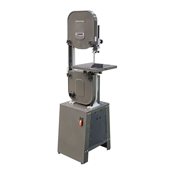
14" WOOD BANDSAW
With DUSt ChUte
Set Up AND OperAtiNg iNStrUCtiONS
Diagrams within this manual may not be drawn proportionally.
Due to continuing improvements, actual product may differ slightly from the product described herein.
Distributed exclusively by harbor Freight tools
Visit our website at: http://www.harborfreight.com
read this material before using this product.
Failure to do so can result in serious injury.
SAVe thiS mANUAl.
Copyright
2001 by Harbor Freight Tools
©
any artwork contained herein may be reproduced in any shape or form without the express
written consent of Harbor Freight Tools.
For technical questions or replacement parts, please call 1-800-444-3353.
3491 Mission Oaks Blvd., Camarillo, CA 93011
32208/
32206
. All rights reserved. No portion of this manual or
®
.
®
manual revised 11h
Advertisement
Table of Contents

Related Manuals for Central Machinery 32208


Summary of Contents for Central Machinery 32208
- Page 1 14” WOOD BANDSAW With DUSt ChUte 32208/ 32206 Set Up AND OperAtiNg iNStrUCtiONS Diagrams within this manual may not be drawn proportionally. Due to continuing improvements, actual product may differ slightly from the product described herein. Distributed exclusively by harbor Freight tools ®...
-
Page 2: Table Of Contents
- Single Speed pulley (32206) ...31 phASe 3: Bandsaw Body to Stand Assembly Diagram and parts list D Assembly ...........11 - Four Speed pulleys (32208) ...31 phASe 4: motor to Stand Assembly ..12 90 DAY WArrANtY ......32 pulley mounting ......12 motor mounting .......13... -
Page 3: Important Safety Information
USE RIGHT TOOL. Don’t force tool or injury. attachment to do a job for which it was not designed. NOtiCe is used to address practices not related to personal injury. SKU 32206/32208 For technical questions, please call 1-800-444-3353. PAGE 3... - Page 4 It’s safer than using your hand and it frees both hands to operate tool. DON’T OVERREACH. Keep proper foot- ing and balance at all times. SKU 32206/32208 For technical questions, please call 1-800-444-3353. PAGE 4...
-
Page 5: Bandsaw Safety Warnings
DO NOt mODiFY, re- equipment, such as those dust masks plACe Or FOrCe the termiNAlS. that are specially designed to filter out SKU 32206/32208 For technical questions, please call 1-800-444-3353. PAGE 5... -
Page 6: Vibration Safety
Do not smoke during use. Nicotine re- nances. duces the blood supply to the hands and SKU 32206/32208 For technical questions, please call 1-800-444-3353. PAGE 6... - Page 7 125 V~ 3-prong plug and Outlet. The tool has a ground- ing plug that looks like the plug illustrated above in 125 V~ 3-prong plug and Outlet. SKU 32206/32208 For technical questions, please call 1-800-444-3353. PAGE 7...
-
Page 8: Specifications
SpeCiFiCAtiONS hardware Bag Contents Note: Hardware sizes illustrated below are Weight 160 lb. (Model 32206) 180 lb. (Model 32208) offered only as a guide and are approxi- Blade Speeds 3000 FPM (Model 32206) mate. 600, 1140, 1670, 2670 FPM Letters given below are for assembly (Model 32208) purposes only. -
Page 9: Assembly
Assemble the Rear Panel (2A) to the ing secured with a Washer (H) and Nut Mounting Plate (1A) in the same way. (K). The Stand should look like the illustration above. SKU 32206/32208 For technical questions, please call 1-800-444-3353. PAGE 9... - Page 10 Switch Cover (13A) from phase 1 securely. as shown above. Attach the Brace (8A) under the Mount- ing Plate (1A) toward the rear as shown. reV 04c; 04g; 05l SKU 32206/32208 For technical questions, please call 1-800-444-3353. PAGE 10...
-
Page 11: Phase 2: Foot Assembly
Insert a Foot Assembly (O) through each Foot Bracket (Q) and Panel (3A, 2A). Secure with Washer (H) and Nut (K). reV 04c; 04g; 05b; 05l SKU 32206/32208 For technical questions, please call 1-800-444-3353. PAGE 11... -
Page 12: Phase 4: Motor To Stand Assembly
(H), Lock Washer (J), and Nut (K). Leave the hardware only finger tight. Measure to verify that the saw body is (Step for 32208 only.) The key for this properly aligned to the stand. Make saw’s Motor shaft will need to be offset needed adjustments, then wrench tight- by about 0.3”... -
Page 13: Motor Mounting
ShAFt Remove the nylon cable tie that secured the Power Cord (14A) during shipment. (Step for 32208 only.) Hold the Pulley in place and insert the depth gauge you made in step 4-2 (Bolt (G) and Nut (N)) into the key slot, pushing the key into position. -
Page 14: Motor Wiring
(grOUND) mOtOr termiNAl BlACK (hOt) mOtOr termiNAl mOtOr COrD 12. The power cord wires are already con- nected at the top connections (black “hot“ wire, white “neutral” wire, and green SKU 32206/32208 For technical questions, please call 1-800-444-3353. PAGE 14... -
Page 15: Phase 5: Table Assembly
Table Bracket (34B) as Bolt (A). Install the Table Stop Bolt into shown above. Secure the Bolts in place the hole noted in the figure above. using Knobs (15B). reV 04g SKU 32206/32208 For technical questions, please call 1-800-444-3353. PAGE 15... -
Page 16: Phase 6: Pulley Cover Assembly And Belt Installation
(23B, not shown), and should not be used to change speeds. (Step for 32208 only.) Using the chart above, choose which speed you would like the blade to operate at initially. Slide the V-Belt (5D) onto the desired Motor Pulley (3D) position. -
Page 17: Side Panel Installation
Stops (39A) point towards the center of the Side Panel (38A). Assemble the Blade Guard (26B) to the Upper Guide Support (27B) as shown above using the two Bolts (59B) already installed in the Support. SKU 32206/32208 For technical questions, please call 1-800-444-3353. PAGE 17... - Page 18 Hold the Upper Guide Support (27B) while you remove the Knob (25B). Gen- Align the Guide Post (24B) if needed and tly lower the Upper Guide Support. secure in place with the Knob (25B). SKU 32206/32208 For technical questions, please call 1-800-444-3353. PAGE 18...
-
Page 19: Phase 8: Saw Blade Installation
Saw Blade (20B) back side first through tABle iNSert (37B) the slot in the Table (36B). tABle piN (38B) Remove the Table Insert (37B) and Table Pin (38B). reV 02d SKU 32206/32208 For technical questions, please call 1-800-444-3353. PAGE 19... - Page 20 If you will attach a dust collector to this Pin (38B). bandsaw, attach the Dust Chute (22B) to the Lower Pulley Guard (21B) using the Bolts (70B) as shown above. SKU 32206/32208 For technical questions, please call 1-800-444-3353. PAGE 20...
-
Page 21: Saw Blade Tensioning And Tracking
Adjust the Upper and Lower Guide Supports (27B, 31B) so that they do not contact the blade during tracking adjust- ment. Loosen the Nut (51B) on the shaft of the Blade Tracking Knob (7B). SKU 32206/32208 For technical questions, please call 1-800-444-3353. PAGE 21... -
Page 22: Guide And Bearing Adjustment
Bearing (47B) to 1/64” (0.4mm) behind the Saw Blade. Then, tighten the Bolt. Loosen the Knobs (15B) under the Table (36B) and pivot the Table forward as far as possible. SKU 32206/32208 For technical questions, please call 1-800-444-3353. PAGE 22... - Page 23 Cover in place with the Knob. to 1/64” (0.4mm) behind the Saw Blade. Then, tighten the Thumb Bolt. Return the Table (36B) to its normal posi- tion and secure with the Knobs (15B) SKU 32206/32208 For technical questions, please call 1-800-444-3353. PAGE 23...
-
Page 24: Settings
Table (36B). Tilt the Table (36B) to the left or right until the Needle points to the desired angle on the Scale (40B). Then, securely tighten both Knobs (15B). SKU 32206/32208 For technical questions, please call 1-800-444-3353. PAGE 24... -
Page 25: Blade Speed Adjustment - For Sku 32208 Only
Do not force the material into the Saw Blade Speed Adjustment Blade. Light contact with the Saw Blade - for SKU 32208 only will permit easier following of the line and prevent undue friction, heating and work- tO preVeNt hardening of the Saw Blade at its back SeriOUS iNjUrY edge. -
Page 26: Maintenance And Servicing
You may use a mild detergent. Bad blade. Replace blade. Once clean, lubricate all moving parts with a light oil. When storing, keep the Bandsaw cov- ered with a cloth cover. SKU 32206/32208 For technical questions, please call 1-800-444-3353. PAGE 26... -
Page 27: Assembly Diagrams And Parts Lists
M8 x Ø18 Switch Lock Washer Switch Cover Star Washer Power Cord Switch Plate Strain Relief Side Panel Pulley Cover Relief Stop Pulley Cover Knob ST Screw M3.5 x 12 SKU 32206/32208 For technical questions, please call 1-800-444-3353. PAGE 27... -
Page 28: Assembly Diagram And Parts List A - Stand
Assembly Diagram A - Stand Note: When ordering parts from Assembly Diagram A, include the suffix “A” after the part number. REV 02d, 04c SKU 32206/32208 For technical questions, please call 1-800-444-3353. PAGE 28... - Page 29 Table Insert Guide Post Cover Table Pin Lower Guide Cover Trunnion Scale Bolt M10 x 20 Trunnion Clamp Shoe Washer M10 x Ø20 Set Screw Miter Gauge Ass’y reV 02d, 04c SKU 32206/32208 For technical questions, please call 1-800-444-3353. PAGE 29...
-
Page 30: Assembly Diagram B - Saw Body
Assembly Diagram B - Saw Body Note: When ordering parts from Assembly Diagram B, include the suffix “B” after the part number. SKU 32206/32208 For technical questions, please call 1-800-444-3353. PAGE 30... -
Page 31: Assembly Diagram And Parts List C
Assembly Diagram and parts list C - Assembly Diagram and parts list D - Single Speed pulley (32206) Four Speed pulleys (32208) Note: When ordering parts from Assembly Note: When ordering parts from Assembly Diagram C, include the suffix “C” after Diagram D, include the suffix “D”... -
Page 32: 90 Day Warranty
This warranty gives you specific legal rights and you may also have other rights which vary from state to state. 3491 Mission Oaks Blvd. • PO Box 6009 • Camarillo, CA 93011 • (800) 444-3353 reV 11h SKU 32206/32208 For technical questions, please call 1-800-444-3353. PAGE 32...
Need help?
Do you have a question about the 32208 and is the answer not in the manual?
Questions and answers
What saw blade does the 32208 take?
The compatible saw blade for Central Machinery part number 32208 has a thickness range of 1/8” to 3/4”.
This answer is automatically generated