Table of Contents
Advertisement
Advertisement
Table of Contents

Related Manuals for Always “On” UPS GES-801V

Summary of Contents for Always “On” UPS GES-801V
- Page 1 Always “On” UPS Systems Inc. GES V-Series – Single Phase Input, Single Phase Output Uninterruptible Power Supply GES-801V, GES-102V, GES-102VR, GES-152V, GES-152VR, GES-222V, GES-222VR Line Interactive (PWM): 800VA, 1kVA, 1.5kVA, 2.2kVA User Manual M0102_V_Series_801-222V_Manual V2.3 2012-06-12...
- Page 2 Always “On” UPS Systems Inc. SAVE THESE INSTRUCTIONS This manual contains important instructions for the GES-801V, GES-102V, GES-102VR, GES-152V, GES-152VR, GES-222V, GES-222VR and should be followed during installation and maintenance of the UPS and batteries. The UPS contains voltages that are potentially hazardous. Please contact our dealers or qualified personnel for service.
- Page 3 Always “On” UPS Systems Inc. SAFETY INSTRUCTIONS The UPS has its own internal energy source (battery), therefore the output receptacles may have electricity present even though the UPS is disconnected from the utility power. The DC voltage provided from the internal battery is 24Vdc for 801V, 102V, 152V, 102VR, 152VR.
-
Page 4: Table Of Contents
Always “On” UPS Systems Inc. Table of Contents INTRODUCTION PRESENTATION 2.1. Front Panel 2.2. Rear Panel INSTALLATION 3.1. Unpacking and Inspection 3.2. Placement 3.3. Connect Computer Interface (Optional) 3.4. Connect to Utility 3.5. Charging the Battery 3.6. Connecting the Loads 3.7. -
Page 5: Introduction
Always “On” UPS Systems Inc. INTRODUCTION The V-Series is a Line Interactive UPS system that includes the newest and latest technology enhancements. The Line Interactive technology with AVR function (on-line voltage boost-up & buck-down) allows for a wide input voltage range of 90 to 150VAC. The V-Series UPS is ideal protection for microprocessor control loads. -
Page 6: Presentation
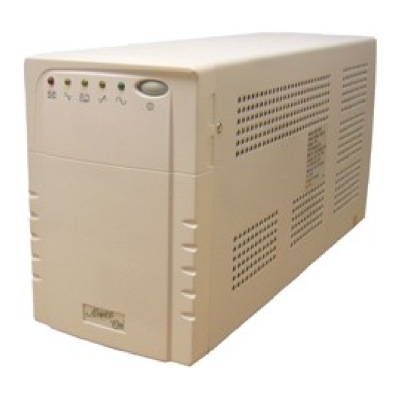
Always “On” UPS Systems Inc. PRESENTATION 2.1. Front Panel Figure 2.1.1 Tower Front Panel. Figure 2.1.2 102VR Front Panel Line Mode Boost INV Mode Buck Battery Fault Always "O n" Figure 2.1.3 152/222VR Front Panel. M0102_V_Series_801-222V_Manual V2.3 2012-06-12... - Page 7 Always “On” UPS Systems Inc. REPLACE BATTERY indicator (RED LED) This LED illuminates when the UPS's batteries are no longer useful and must be replaced. Note: When replacing the batteries, disconnect the utility power and then open the case. Take notice of the polarity before installing the new batteries to avoid a short.
-
Page 8: Rear Panel
Always “On” UPS Systems Inc. 2.2. Rear Panel Rear Panel Figure 2.2.1 Rear Panel Left GES-801, 102, 152V Right GES-222V Figure 2.2.2 Rear Panel GES-102VR INPUT BREAKER REMOTE PORT OUTPUT Figure 2.2. Rear Panel GES- 152VR OUTPUT INPUT BREAKER REMOTE Figure 2.2.2 Rear Panel GES-222VR M0102_V_Series_801-222V_Manual V2.3 2012-06-12... - Page 9 Always “On” UPS Systems Inc. MAIN POWER This toggle switch is the main power cutoff for the UPS. Use of this switch will remove power from loads and completely shutdown the UPS. COMPUTER INTERFACE Both RS-232 and relay signal (Dry Contact) Interfaces are supplied to support WINDOWS, NOVELL, UNIX, DOS, and other operating systems.
-
Page 10: Installation
Always “On” UPS Systems Inc. INSTALLATION 3.1. Unpacking and Inspection Examine the packaging for damage. Inform the carrier immediately if damage is noticed. Retain the packaging for future use. 3.2. Placement Install the UPS in a protected area with adequate airflow and free of excessive dust. -
Page 11: Connecting The Telephone / Modem / Ethernet Lines (Optional)
Always “On” UPS Systems Inc. 3.7. Connecting the Telephone / Modem / Ethernet Lines (Optional) Connect a telephone line, modem line, or 10BaseT line into the telephone / modem / ethernet surge protection sockets on the back of the UPS. The RJ-45 / RJ-11 modular sockets accept standard single line telephone connections and 10BaseT connectors. -
Page 12: Operation
Always “On” UPS Systems Inc. OPERATION 4.1. Switching “On” the UPS For all but the GES-102VR: With the UPS plugged in and utility power present, press and hold the On / Off / Test / Silence Button more than 3 seconds or until the LED is lit. The UPS will perform self-testing each time it is switched “On”. -
Page 13: Shutdown Mode
Always “On” UPS Systems Inc. 4.6. Shutdown Mode In shutdown mode the UPS stops supplying power to the load and waits for the return of utility power. If there is no utility power present, external devices (e.g., servers) connected to the computer interface can command the UPS to shutdown. -
Page 14: Audible Alarm
Always “On” UPS Systems Inc. AUDIBLE ALARM 5.1. Back-Up (Slow Alarm) When in back-up mode, the LED flashes every 2 seconds and the UPS sounds an audible alarm. The alarm stops when the UPS returns to line normal operation. Press the On / Off / Test / Silence Button during back-up mode to silence the beeping. -
Page 15: Computer Interface Port
6.4. Open Collector (Dry Contact) Communication [Pins for the GES-801V, ES-102V and GES-152V] (Pins for the GES-222V) Pin [8] (5) and [6] (2) are open collector outputs that must be pulled up to a common referenced supply no greater than +40VDC. - Page 16 Always “On” UPS Systems Inc. DB-9 Pin Configuration for the GES-801V, 102V, and 152V Low Battery Contacts Mains Failure Normally Open Common UPS Shut Down or RS-232 RD (PIN 3) Signal High Minimum 1 Second RS-232 TX (PIN 2) RS-232 RTS (PIN 7)
-
Page 17: Battery Replacement
Always “On” UPS Systems Inc. BATTERY REPLACEMENT WARNING: Completing the procedure below will void any remaining warranty on the UPS system. Caution: Do not dispose of battery in a fire. Do not attempt to open the battery. When replacing the battery use tools with insulated handles and remove watches, rings, etc…... -
Page 18: Troubleshooting
Always “On” UPS Systems Inc. TROUBLESHOOTING Please follow the guidelines below for common problems: Check UPS input plug and wiring. Check UPS input voltage. Please prepare the information as follows for service personnel: UPS model number and serial number Description of problem(s) in detail. 8.1. -
Page 19: Tower Specifications
Always “On” UPS Systems Inc. TOWER SPECIFICATIONS MODEL GES-801V GES-102V GES-152V GES-222V Capacity 800VA 1kVA 1.5kVA 2.2kVA Voltage 120V, 220V +/-25% INPUT Frequency 50 or 60Hz +/-5% (auto sensing) Voltage (on battery) Simulated sine wave at Line Input +/-5% Frequency (on battery) 50 or 60Hz +/-0.5%... -
Page 20: Rack Mount Specifications
Always “On” UPS Systems Inc. 10. RACK MOUNT SPECIFICATIONS V-SERIES MODEL NO. GES-801V GES-102V GES-152V MAXIMUM CAPACITY 800VA / 495W 1kVA / 600W 1.5kVA / 900W GENERAL 825433 20500 825433 20600 825433 20700 UPC ORDER CODE NOMINAL VOLTAGE 120VAC (optional 220VAC) - Page 21 Always “On” UPS Systems Inc. I/O SPIKE & TRANSIENT PROTECTION COMMUNICATION RS-232 / DRY CONTACT Normal / Back-up / Low Battery / Fault / C INTERFACE LED DISPLAY Buck / Boost AUDIBLE ALARMS On Battery, Low Battery, Overload OPERATING 0 - 40°C (32 - 104°F) TEMPERATURE ENVIRONMENT HUMIDITY...
-
Page 22: Contact Information
Always “On” UPS Systems Inc. 11. CONTACT INFORMATION 11.1. Additional Purchases or Upgrades Always “On” UPS Systems Inc. Bldg 1 – 150 Campion Road, Kelowna, BC, Canada, V1X 7S8 Phone: (250) 491-9777 Ext 451 Fax: (250) 491-9775 Email: sales@alwaysonups.com Website: www.alwaysonups.com 11.2.
Need help?
Do you have a question about the GES-801V and is the answer not in the manual?
Questions and answers