Table of Contents
Advertisement
SERVICE MANUAL
Ver 1.0 1999. 03
MICROFILM
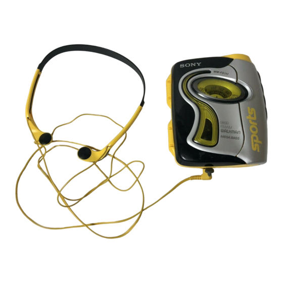
WM-FS111
SPECIFICATIONS
Radio Frequency
FM : 87.6 – 108 MHz
(North, Central and South America)
87.5 – 108 MHz (Italy and Saudi Arabia)
65 – 107.9 MHz (Eastern Europe)
87.6 – 107.9 MHz (Other countries)
AM : 530 – 1,710 kHz
(North, Central and South America)
526.5 – 1,606.5 kHz (Italy and Saudi Arabia)
531 – 1,602 kHz (Other countries)
3 V DC Batteries R6 (AA) × 2
Power Requirements
104.0 × 122.0 × 48.7 mm(4
Dimensions
(w/h/d) incl. projecting parts and controls
Mass
Approx. 300 g (10.6 oz)
Approx. 380 g (13.5 oz) incl. batteries and a cassette
Supplied Accessories
• Stereo headphones or stereo earphones (1)
• Belt clip (1)
Design and specifications are subject to change without notice.
Canadian Model
Model Name Using Similar Mechanism
Tape Transport Mechanism Type
× 4
× 1
1
/
7
/
15
/
inches)
8
8
16
RADIO CASSETTE PLAYER
US Model
AEP Model
E Model
NEW
MF-WMFS111-114
Advertisement
Table of Contents

Related Manuals for Sony WM-FS111


Summary of Contents for Sony WM-FS111
- Page 1 WM-FS111 SERVICE MANUAL US Model Canadian Model Ver 1.0 1999. 03 AEP Model E Model Model Name Using Similar Mechanism Tape Transport Mechanism Type MF-WMFS111-114 SPECIFICATIONS Radio Frequency FM : 87.6 – 108 MHz (North, Central and South America) 87.5 – 108 MHz (Italy and Saudi Arabia) 65 –...
-
Page 2: Table Of Contents
SECTION 1 GENERAL TABLE OF CONTENTS 1. GENERAL ·········································································· 2 2. SERVICE NOTE 2-1. How to Install The Wire Assembly ····································· 3 2-2. Water Proof Section ···························································· 3 3. DISASSEMBLY 3-1. Holder Cassette Sub Assembly and Dial Scale ·················· 4 3-2. -
Page 3: Service Note
NOTE : In case the parts in the figure are removed for repair, treat them to protect from water drop following the instructions in the figure (spread grease, bond etc.) • sony grease SGL-601 : 7-651-000-10 Tapping screw (B)(1.4x6) Gear (A) Gear (VOL) Tapping screw (B)(1.4x6) -
Page 4: Disassembly
SECTION 3 DISASSEMBLY Note : Disassemble the unit in the order as shown below. Holder cassette sub assembly and dial scale Mechanism deck Magnetic head Main assembly Main board Belt Note : Follow the disassembly procedure in the numerical order given. 3-1. -
Page 5: Main Assembly
3-2. MAIN ASSEMBLY 2 Two screws (+B1.7 × 7) 3 Remve the main assembly in the direction of arrow. (Be careful not to focibly pull the wire that connects the main board and the headphone board.) 4 Remove the headphone borad in the direction of arrow. -
Page 6: Main Board
3-3. MAIN BOARD 3 Tooth screw ( M1.4) 1 Remove the solder (four points) 5 Main board 4 Two claws 2 Flexible board (head) 3-4. MECHANISM DECK 2 Remove the mechanism deck in the direction of arrow. 1 Two claws —... -
Page 7: Belt
3-5. BELT Belt Belt threading Capstan wheel assy(SP) Reel/Capstan motor Belt 3-6. MAGNETIC HEAD 1 Two screws (M1.4) 2 Magnetic head (HP301) — 7 —... -
Page 8: Mechanical Adjustment
SECTION 4 SECTION 5 MECHANICAL ADJUSTMENT ELECTRICAL ADJUSTMENT PRECAUTION 0dB=0.775V TAPE SECTION Clean the following parts with a denatured-alcohol-moistened swab: playback head pinch roller Test Tape rubber belts capstan Tape Signal Used for Demagnetize the playback head with a head demagnetizer. WS-48A 3 kHz, 0 dB Tape speed adjustment... - Page 9 • Repeat the procedures in each adjustment several times for the 0 dB = 1 µV TUNER SECTION maximum level meter indication. • Switch Location • The frequency coverage and tracking adjustments should be finally done by the trimmer capacitors. VOLUME : MAX MEGA BASS : OFF...
- Page 10 [MAIN BOARD] — Component side — FM Frequency Coverage Adjustment FM Tracking Adjustment AM Tracking Adjustment AM IF AM Frequency Adjustment Coverage Adjustment — Conductor side — TP18 FM IN — 10 —...
-
Page 11: Diagrams
WM-FS111 SECTION 6 DIAGRAMS 6-1. BLOCK DIAGRAM S305 US,CND,MX LOCAL/DX MODEL AVLS SWITCH FM/AM RF,IF AMP S306 LIMIT NORM DET,MPX FERITE-ROD MEGA BASS ANTENNA CV1,CTI-CT4 Q203 TUNING AVLS SWITCH J301 FM RF IN CV1(1/4) Q101 Q102 VREF TRACKING AM RF IN MEGA 10.7MHz... -
Page 12: Printed Wiring Board
WM-FS111 6-2. PRINTED WIRING BOARD Note on Printed Wiring Board: • Semiconductor Location • X : parts extracted from the component side. Ref. No. Location Ref. No. Location Ref. No. Location • Y : parts extracted from the conductor side. -
Page 13: Schematic Diagram
WM-FS111 6-3. SCHEMATIC DIAGRAM Note on Schematic Diagram: • All capacitors are in µF unless otherwise noted. pF: µµF 50 WV or less are not indicated except for electrolytics • Voltages are taken with a VOM (Input impedance 10 MΩ). -
Page 14: Ic Block Diagrams
WM-FS111 SECTION 7 EXPLODED VIEWS 6-4. IC BLOCK DIAGRAMS IC1 TA2111F-(EL) NOTE: • -XX, -X mean standardized parts, so they may • The mechanical parts with no reference number When indicating parts by reference number, have some differences from the original one. - Page 15 7-2. MAIN BOARD SECTION mechanism deck not supplied Ref. No. Part No. Description Remarks Ref. No. Part No. Description Remarks X-3377-165-1 CHASSIS SUB ASSY (AEP,E) 3-032-146-01 BUTTON (STOP) X-3377-166-1 CHASSIS SUB ASSY (US,CND,MX) 3-921-955-01 SCREW (M1.4), TOOTH (WH) 3-934-020-31 LID,BATTERY CASE A-3021-212-A MAIN BOARD, COMPLETE (US,CND,MX) 3-936-792-01 SPRING, TORSION A-3021-214-A MAIN BOARD, COMPLETE (AEP,E)
- Page 16 7-3. CABINET (REAR) ASSY SECTION Ref. No. Part No. Description Remarks Ref. No. Part No. Description Remarks 3-318-203-62 SCREW (B1.7 × 4), TAPPING 3-032-165-11 CABINET (REAR) (BLACK) (CND) 3-032-164-01 PLATE, LOCK 3-032-165-21 CABINET (REAR) (BLUE) (CND) 3-032-163-01 BUCKLE (YELLOW) 3-914-156-01 WINDOW, LED 3-032-163-11 BUCKLE (BLACK) (CND) 3-934-002-01 GEAR (VOL) 3-032-163-21 BUCKLE (BLUE) (CND)
-
Page 17: Mechanism Deck Section
7-4. MECHANISM DECK SECTION 1 (MF-WMFS111-114) HP301 M901 Ref. No. Part No. Description Remarks Ref. No. Part No. Description Remarks 3-013-560-11 BELT X-3369-749-1 PINCH LEVER (N) ASSY 3-703-816-31 SCREW (M1.4), SPECIAL HEAD 3-920-996-01 SPRING (PINCH N) 3-019-776-01 GEAR (REEL-S) HP301 1-500-517-11 HEAD, MAGNETIC (PLAYBACK) 3-703-816-73 SCREW (M1.4), SPECIAL HEAD M901... - Page 18 7-5. MECHANISM DECK SECTION 2 (MF-WMFS111-114) Ref. No. Part No. Description Remarks Ref. No. Part No. Description Remarks 3-921-797-01 WASHER 3-019-778-01 SLEEVE (MS) 3-921-003-01 BEARING 3-921-335-01 WASHER, LEVER 3-938-628-01 SPRING (PLAY-CP) 3-920-990-01 SPRING (UD), COMPRESSION 3-019-773-01 GEAR (AS) 3-019-774-01 GEAR (BS) X-3374-598-1 CLUTCH ASSY (S) X-3369-747-1 WHEEL ASSY (SP), CAPSTAN 3-022-093-01 SPRING (FR-S)
-
Page 19: Electrical Parts List
SECTION 8 MAIN ELECTRICAL PARTS LIST NOTE: • Due to standardization, replacements in the • CAPACITORS: • SEMICONDUCTORS parts list may be different from the parts uF: µF In each case, u: µ, for example: specified in the diagrams or the components •... - Page 20 MAIN Ref. No. Part No. Description Remarks Ref. No. Part No. Description Remarks C605 1-110-563-11 CERAMIC CHIP 0.068uF JC22 1-216-296-91 SHORT C606 1-124-434-00 ELECT 220uF JC23 1-216-296-91 SHORT C607 1-164-344-11 CERAMIC CHIP 0.068uF JC24 1-216-296-91 SHORT C608 1-165-176-11 CERAMIC CHIP 0.047uF JC25 1-216-296-91 SHORT...
- Page 21 MAIN HEADPHONE Ref. No. Part No. Description Remarks Ref. No. Part No. Description Remarks R104 1-216-835-11 METAL CHIP 1/16W < SWITCH > R105 1-216-819-11 METAL CHIP 1/16W R107 1-216-864-11 METAL CHIP 1/16W S301 1-692-605-31 SWITCH, SLIDE (FUNCTION) R108 1-216-811-11 METAL CHIP 1/16W S302 1-771-092-21 SWITCH, PUSH (1 KEY) (0/(/))
- Page 22 WM-FS111 Sony Corporation 99C1682-1 Printed in Japan ©1999.3 Personal A&V Products Company 9-926-980-11 Published by Quality Engineering Dept. — 26 — (Shinagawa)
Need help?
Do you have a question about the WM-FS111 and is the answer not in the manual?
Questions and answers