Table of Contents
Advertisement
Quick Links
SERVICE MANUAL
Ver 1.0
1998. 05
MICROFILM
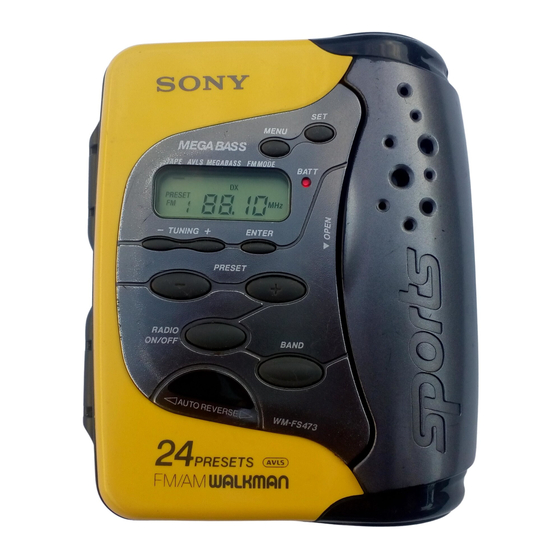
WM-FS473
SPECIFICATIONS
Frequency range
FM : 87.5 – 108 MHz
AM : 530 – 1710kHz
(US, Canadian model)
531 – 1602kHz (AEP, E model)
Power requirements 3V DC batteries (AA) R6 x2
Dimensions
104.2 x 127.3 x 51.8 mm (4
(w/h/d) incl. projecting parts and controls
Mass
Approx. 260g (9.2 oz)
Approx.340g (12 oz) incl. batteries and a cassette
Supplied accessory
Stereo headphones or Stereo earphones (1)
Design and specifications are subject to change without notice.
Canadian Model
Model Name Using Similar Mechanism
Tape Transport Mechanism Type
1
1
1
/
x 5
/
x 2
/
inches)
8
8
8
RADIO CASSETTE PLAYER
US Model
AEP Model
E Model
NEW
MF-WMFS473
Advertisement
Table of Contents

Related Manuals for Sony WM-FS473


Summary of Contents for Sony WM-FS473
- Page 1 WM-FS473 SERVICE MANUAL US Model Canadian Model Ver 1.0 1998. 05 AEP Model E Model Model Name Using Similar Mechanism Tape Transport Mechanism Type MF-WMFS473 SPECIFICATIONS Frequency range FM : 87.5 – 108 MHz AM : 530 – 1710kHz (US, Canadian model) 531 –...
-
Page 2: Table Of Contents
TABLE OF CONTENTS Specifications ................1 Flexible Circuit Board Repairing • Keep the temperature of the soldering iron around 270°C 1. GENERAL during repairing. • Do not touch the soldering iron on the same conductor of the Location of parts and controls ..........2 circuit board (within 3 times). -
Page 3: Service Note
Note : In case the parts in the figure are removed for repair, treat them to protect from water drop following the instructions in the figure (spread grease, bond etc.) • Sony grease SGL-601 : 7-651-000-10 Paking (cabinet) Set the A positions to corner. -
Page 4: Disassembly
SECTION 3 DISASSEMBLY The equipment can be remo ved using the f ollo wing pr ocedure . Cover Diaplay board Cassette lid assy Chassis section, Headphone jack board Mechanism deck, Main board, Belt Note : Follow the disassembly procedure in the numerical order given. 3-1. -
Page 5: Cassette Lid Assy Removal
3-3. CASSETTE LID ASSY REMOVAL Cassette lid assy 2 Screw 2 Screw 1 Flexible board 3-4. CHASSIS SECTION, HEADPHONE JACK BOARD REMOVAL 1 Screws (+P 2x12) Chassis section Note : When install the c hassis section 1. Turn R V301 full y to arr ow direction. 2. -
Page 6: Mechanism Deck, Main Board, Belt Removal
3-5. MECHANISM DECK, MAIN BOARD, BELT REMOVAL 2 Screws (2x5) Chassis 3 Claw 3 Claw 3 Claw 5 Screw Belt Mechanism deck Black Gray Orange 1 Remove solder Black Main board White – 6 –... -
Page 7: Adjustments
SECTION 4 ADJUSTMENTS 4-1. MECHANICAL ADJUSTMENTS 4-2. ELECTRICAL ADJUSTMENTS PRECAUTION PRECAUTION 1. Clean the following parts with a denatured-alcohol-moistened • Supplied v olta ge : 2.5V. swab : • Switch and control position playback head pinch roller SET switch : NORM capstan rubber belt VOLUME control : maximum... - Page 8 TUNER SECTION no mark : COM < > : AEP, E model onl y AM Section AM IF ALIGNMENT BAND : AM Adjust for a maximum reading on level meter. AM RF signal Put the lead-wire 450kHz generator antenna close to the set.
- Page 9 Connection Point : [MAIN BOARD] (Component side) Adjustment Location : [MAIN BOARD] (Conductor Side) T1 : AM IF Alignment L3 : FM Frequency Coverage Adjustment T2 : AM Frequency Coverage Adjustment L2 : FM Tracking Adjustment L1 : AM Tracking Adjustment CT1 : AM Tracking Adjustment –...
-
Page 10: Diagrams
SECTION 5 DIAGRAMS 5-1. EXPLANATION OF IC TERMINALS IC701 TC9322FB-603 (LCD DRIVE/SYSTEM CONTROL) Pin No. Pin name Description 1 – 3 COM1 – COM3 Common output terminal. 4 – 20 S1 – S17 Segment output terminal. 21 – 26 KR0 – KR5 Key return timing output terminal. -
Page 11: Block Diagram
WM-FS473 5-2. BLOCK DIAGRAM • Signal path. : FM : PB – 11 – – 12 –... -
Page 13: Schematic Diagram (Main Section)
5-4. SCHEMATIC DIAGRAM (MAIN SECTION) WM-FS473 WAVEFORMS 2.8Vp-p 4.1Vp-p 0.38 µ sec 0.38 µ sec VOLT/DIV : 1V AC VOLT/DIV : 0.5V AC TIME/DIV : 0.1 µsec TIME/DIV : 0.1 µsec IC BLOCK DIAGRAM IC1 TA2137FN (EL) BUFF DECOOE BUFF... -
Page 14: Schematic Diagram (Display Section)
WM-FS473 5-5. SCHEMATIC DIAGRAM (DISPLAY SECTION) WAVEFORM 1.1Vp-p 75kHz 13.6 µ sec VOLT/DIV : 0.2V AC IC701 %• TIME/DIV : 5 µsec IC BLOCK DIAGRAM IC702 PST9018NL – – Note: • All capacitors are in µF unless otherwise noted. pF: µµF 50 WV or less are not indicated except for electrolytics and tantalums. -
Page 16: Exploded Views
SECTION 6 EXPLODED VIEWS NOTE : 6-2. MAIN BOARD SECTION • -XX, -X mean standardized parts, so they • The mechanical parts with no reference may have some difference from the original number in the exploded views are not one. supplied. -
Page 17: Mechanism Deck Section (Mf-Wmfs473)
Ref. No. Part No. Description Remark Ref. No. Part No. Description Remark 6-3. MECHANISM DECK SECTION 3-025-064-01 SPRING (DIR) 3-381-883-01 SCREW (MOTOR) (MF-WMFS473) X-3375-574-1 CHASSIS ASSY 3-025-073-01 SPRING 3-025-074-01 ARM PINCH R 3-025-060-01 WASHER (UPPER&LOWER) 3-905-717-01 PINCH ROLLER (R) 3-025-065-01 SLIDE PLATE 3-905-710-01 ARM (TU) HP901 3-025-053-01 LEVER (WEDGE) -
Page 18: Electrical Parts List
DISPLAY SECTION 7 MAIN ELECTRICAL PARTS LIST HEADPHONE JACK Ref. No. Part No. Description Remark Ref. No. Part No. Description Remark NOTE : A-3021-088-A MAIN BOARD, COMPLETE (US, CND) 1-162-905-11 CERAMIC CHIP 0.25PF 50V • Due to standardization, replacements in the •... - Page 19 MAIN Ref. No. Part No. Description Remark Ref. No. Part No. Description Remark 8-719-420-14 DIODE 02DZ12-TPH3 8-729-230-38 TRANSISTOR 2SC4215Y D301 8-719-049-09 DIODE 1SS367-T3SONY 8-729-029-15 TRANSISTOR DTC144TUA-T106 8-729-230-38 TRANSISTOR 2SC4215Y < IC > Q101 8-729-028-97 TRANSISTOR DTC114TUA-T106 8-759-544-03 IC TA2137FN(EL) Q102 8-729-602-21 TRANSISTOR 2SC4154-F IC301 8-759-497-06 IC MM1316AFBE...
- Page 20 WM-FS473 MAIN SWITCH Ref. No. Part No. Description Remark Ref. No. Part No. Description Remark R251 1-216-839-11 METAL CHIP 1/16W 8-952-478-90 HEADPHONE MDR-E215/Y SET (AEP,E) 8-953-142-90 HEADPHONE MDR-W14G//K SET (US, CND) R252 1-216-825-11 METAL CHIP 2.2K 1/16W R301 1-216-841-11 METAL CHIP...
Need help?
Do you have a question about the WM-FS473 and is the answer not in the manual?
Questions and answers