Table of Contents
Advertisement
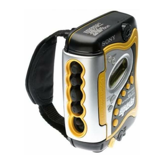
WM-FS420/FS420RS
SERVICE MANUAL
Ver 1.2 2001. 03
Sony Corporation
9-927-679-12
2001C1600-1
Audio Entertainment Group
© 2001.3
General Engineering Dept.
SPECIFICATIONS
Radio Frequency
FM : 87.5 – 108 MHz
AM : 530 – 1,710 kHz
(North, Central and South America)
531 – 1,602 kHz (Other countries)
3 V DC Batteries R6 (AA) × 2
Power Requirements
Approx. 108.4 × 125.7 × 47.2 mm
Dimensions (w/h/d)
× 5 × 1
3
(4
/
8
projecting parts and controls
Mass
Approx. 280 g (9.9 oz)/Approx. 355 g (12.6 oz)
(incl. batteries and a cassette)
Supplied Accessories
• Stereo headphones or earphones (1)
• Belt clip (1)
• Battery charger (1) (FS420RS only)
• Rechargeable battery
NC-WMAA, 1.2 V, 700 mAh, Ni-Cd (2) (FS420RS only)
• Rechargeable battery carrying case (1) (FS420RS only)
Design and specifications are subject to change without notice.
Model Name Using Similar Mechanism
Tape Transport Mechanism Type
7
/
inches) incl.
8
RADIO CASSETTE PLAYER
US Model
Canadian Model
WM-FS420/FS420RS
AEP Model
E Model
WM-FS420
NEW
MF-WMFS420-114
Advertisement
Table of Contents


Need help?
Do you have a question about the WALKMAN WM-FS420RS and is the answer not in the manual?
Questions and answers