Table of Contents
Advertisement
CONTENTS
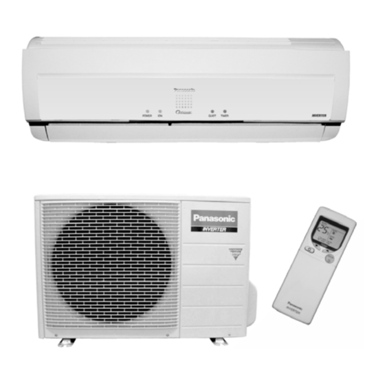
CS-XE9CKE CU-XE9CKE
CS-XE12CKE CU-XE12CKE
Page
2
3
6
10
12
13
14
15
15
30
40
52
60
© 2004 Matsushita Industrial Corp. Sdn. Bhd.
(11969-T). All rights reserved. Unauthorized copying
and distribution is a violation of law.
Order No. MAC0403017C2
Air Conditioner
Page
60
63
67
71
71
72
76
78
82
82
84
86
Advertisement
Table of Contents
Troubleshooting

Related Manuals for Panasonic CS-XE9CKE


Summary of Contents for Panasonic CS-XE9CKE
-
Page 1: Table Of Contents
Order No. MAC0403017C2 Air Conditioner CS-XE9CKE CU-XE9CKE CS-XE12CKE CU-XE12CKE CONTENTS Page Page 1 Features 10.1. SAFETY PRECAUTIONS 2 Functions 10.2. INDOOR UNIT 3 Product Specifications 10.3. OUTDOOR UNIT 4 Dimensions 11 Installation and Servicing Air Conditioner Using R410A 5 Refrigeration Cycle Diagram 11.1. -
Page 2: Features
CS-XE9CKE CU-XE9CKE / CS-XE12CKE CU-XE12CKE 12.4. DISASSEMBLY OF PARTS 18.3. PRINT PATTERN INDOOR UNIT PRINTED CIRCUIT 13 Technical Data BOARD (POWER) 14 Exploded View 18.4. PRINT PATTERN INDICATOR DISPLAY 15 Replacement Parts List 18.5. PRINT PATTERN OUTDOOR UNIT PRINTED CIRCUIT... -
Page 3: Functions
CS-XE9CKE CU-XE9CKE / CS-XE12CKE CU-XE12CKE 2 Functions Remote Control Illuminable buttons FAN SPEED Indoor Fan Speed Selection • • Medium- • Medium OFF/ON • Medium+ • High Operation OFF / ON AUTO • Automatic Fan Speed MODE TEMP Operation Mode Selection Room Temperature Setting •... - Page 4 CS-XE9CKE CU-XE9CKE / CS-XE12CKE CU-XE12CKE Indoor Unit AUTO Automatic and 5 Manual Vertical OFF / ON Automatic Operation Button Airflow Directions Press for < 5s to operate Automatic operation mode. (Used when the remote control cannot be used.) Automatic and 5 Manual Horizontal Press continuously for 5s or <...
- Page 5 CS-XE9CKE CU-XE9CKE / CS-XE12CKE CU-XE12CKE Outdoor Unit Time Delay Safety Control 30 seconds Forced Operation Overload Protection Total Running Current Control Compressor Overheating Prevention Control IPM (Power Transistor) Overheating Protection Control Low Operation Frequency Protection Control Outdoor Air Temperature Control...
-
Page 6: Product Specifications
CS-XE9CKE CU-XE9CKE / CS-XE12CKE CU-XE12CKE 3 Product Specifications Unit CS-XE9CKE CU-XE9CKE Cooling Capacity 2.6 (0.60 - 3.00) kcal/h 2,240 (520 - 2,580) BTU/h 8,870 (2,050 - 10,200) Heating Capacity 3.6 (0.60 - 5.00) kcal/h 3,100 (520 - 4,300) BTU/h 12,300 (2,050 - 17,100) - Page 7 CS-XE9CKE CU-XE9CKE / CS-XE12CKE CU-XE12CKE Unit CS-XE9CKE CU-XE9CKE Drain Inner diameter — Hose Length 0.65 — Power Cord Length 2.1 m — Number of core-wire 3 core wires × 1.0 mm — Dimensions Height inch (mm) 10 - 26/32 (275)
- Page 8 CS-XE9CKE CU-XE9CKE / CS-XE12CKE CU-XE12CKE Unit CS-XE12CKE CU-XE12CKE Cooling Capacity 3.45 (0.60 - 4.00) kcal/h 2,970 (520 - 3,440) BTU/h 11,800 (2,050 - 13,600) Heating Capacity 4.80 (0.60 - 6.50) kcal/h 4,130 (520 - 5,590) BTU/h 16,400 (2,050 - 22,200)
- Page 9 CS-XE9CKE CU-XE9CKE / CS-XE12CKE CU-XE12CKE Unit CS-XE12CKE CU-XE12CKE Dimensions Height inch (mm) 10 - 26/32 (275) 21 - 9/32 (540) Width inch (mm) 31 - 15/32 (799) 30 - 23/32 (780) Depth inch (mm) 9 - 9/32 (236) 11 - 3/8 (289)
-
Page 10: Dimensions
CS-XE9CKE CU-XE9CKE / CS-XE12CKE CU-XE12CKE 4 Dimensions... - Page 11 CS-XE9CKE CU-XE9CKE / CS-XE12CKE CU-XE12CKE...
-
Page 12: Refrigeration Cycle Diagram
CS-XE9CKE CU-XE9CKE / CS-XE12CKE CU-XE12CKE 5 Refrigeration Cycle Diagram... -
Page 13: Block Diagram
CS-XE9CKE CU-XE9CKE / CS-XE12CKE CU-XE12CKE 6 Block Diagram... -
Page 14: Wiring Diagram
CS-XE9CKE CU-XE9CKE / CS-XE12CKE CU-XE12CKE 7 Wiring Diagram... -
Page 15: Operation Details
CS-XE9CKE CU-XE9CKE / CS-XE12CKE CU-XE12CKE 8 Operation Details 8.1. BASIC FUNCTION Inverter control, which equipped with a microcomputer in determining the most suitable operating mode as time passes, automatically adjusts output power for maximum comfort always. In order to achieve the suitable operating mode, the microcomputer maintains the set temperature by measuring the temperature of the environment and performing temperature shifting. - Page 16 CS-XE9CKE CU-XE9CKE / CS-XE12CKE CU-XE12CKE Table (b): Outdoor Air Temperature Shifting Mode: Outdoor Temperature, X (°C): Temperature Shift (°C) XE9CK XE12CK Cooling/Soft Dry 0.00 0.00 0.00 0.00 0.00 0.00 0.00 0.00 Heating 0.00 0.00 0.00 0.00 0.00 0.00 +0.50 +1.00 +1.00...
-
Page 17: Compressor Operation Frequency
CS-XE9CKE CU-XE9CKE / CS-XE12CKE CU-XE12CKE 8.1.2. Compressor Operation Frequency Zone Intake Air Temperature - Internal Setting Temperature (°C) Freq. H Cooling Soft Dry Heating Cooling Soft Dry Heating Remark XE9CK XE12CK XE9CK XE12CK XE9CK XE12CK -2.0 -3.0 -1.5 -2.5 -1.0 -2.0... -
Page 18: Soft Dry Operation
CS-XE9CKE CU-XE9CKE / CS-XE12CKE CU-XE12CKE 8.1.4. Soft Dry Operation 8.1.4.1. Thermostat control • • • • Compressor is OFF when Intake Air Temperature - Internal Setting Temperature < -2.5°C. • • • • Compressor is ON after waiting for 3 minutes, if the Intake Air Temperature - Internal Setting Temperature > Compressor OFF point. -
Page 19: Indoor Fan Motor Operation
CS-XE9CKE CU-XE9CKE / CS-XE12CKE CU-XE12CKE Values of T1, T2, and T3 depend on remote control setting temperature, as shown in below table. After the adjustment of T1, T2 and T3 values, the operation mode for that particular environment and remote control setting is judged and performed, based on the above operation mode chart, every 30 minutes. - Page 20 CS-XE9CKE CU-XE9CKE / CS-XE12CKE CU-XE12CKE B. Indoor Fan Control i. Indoor fan control operation outline 1. Cooling / Dry / Fan / Ion / Oxygen 2. Heating...
- Page 21 CS-XE9CKE CU-XE9CKE / CS-XE12CKE CU-XE12CKE ii. Auto Fan Speed 1. Cooling, Ion, Oxygen 2. Heating Note: a. UP: • • • • If move from Lo, the fan speed will be shifted to Maximum 1160 rpm (XE9CK), 1330 rpm (XE12CK).
- Page 22 CS-XE9CKE CU-XE9CKE / CS-XE12CKE CU-XE12CKE iii. Max Capacity Condition a) During Cooling operation, if all to the following condition is fulfilled, the indoor fan speed is set to Shi. 1. Indoor intake temperature 24°C. 2. Operation frequency 39 Hz (XE9CK), 52 Hz (XE12CK) & above.
-
Page 23: Outdoor Fan Motor Operation
CS-XE9CKE CU-XE9CKE / CS-XE12CKE CU-XE12CKE D. Deodorizing Control i. Control condition Control at cooling/dry operation and auto fan speed setting. No Deodorizing Control is performed during ON timer standby operation and during Anti-freezing control prevention. ii. Operation The odor status is arranged as below and it is shifted as follow. -
Page 24: Airflow Direction
CS-XE9CKE CU-XE9CKE / CS-XE12CKE CU-XE12CKE 8.1.9. Airflow Direction 1. There are two types of airflow, vertical airflow (directed by horizontal vane) and horizontal airflow (directed by vertical vanes). 2. Control of airflow direction can be automatic (angles of direction is determined by operation mode, heat exchanger temperature and intake air temperature) and manual (angles of direction can be adjusted using remote control). - Page 25 CS-XE9CKE CU-XE9CKE / CS-XE12CKE CU-XE12CKE 2. Manual horizontal airflow direction can be set using remote control; the angles of the vane are as stated below and the positions of the vane are as Figure 2 above. Pattern Airflow Direction Patterns at Remote Control Vane Angle (°)
-
Page 26: Quiet Operation (Heating)
CS-XE9CKE CU-XE9CKE / CS-XE12CKE CU-XE12CKE Manual Fan Speed (Dry operation) 8.1.10.2. Quiet operation (Heating) A. Purpose To provide quiet heating operation compare to normal operation. B. Control condition a. Quiet operation start condition • • • • When “quiet” button at remote control is pressed. -
Page 27: Auto Restart Control
CS-XE9CKE CU-XE9CKE / CS-XE12CKE CU-XE12CKE 8.1.11. Delay ON Timer Control Delay ON timer can be set using remote control, the unit with timer set will start operate earlier than the setting time. This is to provide a comfortable environment when reaching the set ON time. -
Page 28: Indoor Power Relay Control
CS-XE9CKE CU-XE9CKE / CS-XE12CKE CU-XE12CKE 4. When the switch is pressed between 11 to 16 seconds and together with the signal from remote control, the unit can be changed to different controlling setting (A-B mode) or to testify oxygen operation. - Page 29 CS-XE9CKE CU-XE9CKE / CS-XE12CKE CU-XE12CKE control is pressed. Ionizer on & ION LED illuminates. (3 → 4) Power LED also illuminates. 2. Ionising Operation Stop Condition When one of the following condition is satisfied, ION operation stops. a. Stopped by ON/OFF switch.
-
Page 30: Protection Control Features
CS-XE9CKE CU-XE9CKE / CS-XE12CKE CU-XE12CKE 8.1.16.2. Ionizer Operation case study Case 1 8.2. PROTECTION CONTROL FEATURES 8.2.1. Protection Control For All Operations 8.2.1.1. Time Delay Safety Control 1. The compressor will not start for three minutes after stop of operation. - Page 31 CS-XE9CKE CU-XE9CKE / CS-XE12CKE CU-XE12CKE 4. The first 30 minutes of cooling operation, (A) will be applied. 8.2.1.4. IPM (Power transistor) Prevention Control A. Overheating Prevention Control 1. When the IPM temperature rises to 110°C, compressor operation will stop immediately.
- Page 32 CS-XE9CKE CU-XE9CKE / CS-XE12CKE CU-XE12CKE 8.2.1.6. Low Pressure Prevention Control (Gas Leakage Detection) 1. When the conditions listed in below table occur, the compressor stops and restarts after three minutes. 2. If this phenomenon is continuously occurring for twice within 20 minutes, all indoor and outdoor relays will be cut off.
-
Page 33: Outdoor Air Temperature Control
CS-XE9CKE CU-XE9CKE / CS-XE12CKE CU-XE12CKE 8.2.2. Protection Control For Cooling & Soft Dry Operation 8.2.2.1. Outdoor Air Temperature Control The compressor operating frequency is regulated in accordance to the outdoor air temperature as shown in the diagram below. 8.2.2.2. Cooling Overload Control i. - Page 34 CS-XE9CKE CU-XE9CKE / CS-XE12CKE CU-XE12CKE 8.2.2.4. Anti-Dew Formation Control Anti-Dew control is perform if the following conditions is fulfilled during cooling/dry operation. a. Control Start Condition 1) Indoor Intake Air Temperature 24°C & above 2) Outdoor Air Temperature Refer below 3) Remote Control Setting Temperature 16°C &...
-
Page 35: Protection Control For Heating Operation
CS-XE9CKE CU-XE9CKE / CS-XE12CKE CU-XE12CKE 8.2.3. Protection Control For Heating Operation 8.2.3.1. Anti Cold Draft Control Indoor fan speed varies in accordance to indoor heat exchanger temperature, based on type of air volume and direction, as shown below. 1. Manual Fan Speed... - Page 36 CS-XE9CKE CU-XE9CKE / CS-XE12CKE CU-XE12CKE Note: a. UP: • • • • If move from Lo, the fan speed will be shifted to Maximum 1160 rpm (XE9CK), 1330 rpm (XE12CK). • • • • If move from Maximum, the fan speed no change.
- Page 37 CS-XE9CKE CU-XE9CKE / CS-XE12CKE CU-XE12CKE 8.2.3.4. Overload Protection Control The compressor operating frequency is regulated in accordance to indoor heat exchanger temperature as shown in below figures. 8.2.3.5. Preliminary Operation Control 1. Purpose To improve heating cool start characteristich in which compared to previous model, achived 40°C of discharge air in shorter time.
-
Page 38: Deice Control
CS-XE9CKE CU-XE9CKE / CS-XE12CKE CU-XE12CKE 8.2.3.6. Deice Control A. Deice operation (Normal Deice Operation) 1. Detection methods Outdoor heat exchanger temperature sensor, timer. 2. Deice operation time chart Notes a. During deice operation, the relationship between outdoor pipe temperature and time T5 is such operation will proceed to next stage. - Page 39 CS-XE9CKE CU-XE9CKE / CS-XE12CKE CU-XE12CKE 3. Explaination of operation 1) Before the deice is started, compressor frequency is set to the specified value for T1-timer. 2) After deice is started, the 4-way valve, OD Fan and ID fan are OFF.
-
Page 40: Oxygen Enrich Operation
CS-XE9CKE CU-XE9CKE / CS-XE12CKE CU-XE12CKE 8.3. OXYGEN ENRICH OPERATION 8.3.1. Purpose Increase usage range by enable oxygen enrichment only operation. 8.3.2. Oxygen Enrichment Control -1 A. Indoor fan control 1. Air flow volume manual Air flow volume as set by remote control. Speed same as for Cool mode. - Page 41 CS-XE9CKE CU-XE9CKE / CS-XE12CKE CU-XE12CKE 2. When operate together with ON/OF timer. a. ON timer is set during operation stop. Previous operation is Oxygen only, → Previous mode (Auto, Heat, Cool, Dry, Fan) only will operate. b. ON timer is set during Oxygen only operation.
- Page 42 CS-XE9CKE CU-XE9CKE / CS-XE12CKE CU-XE12CKE B. Oxygen enrich control overview Upon receiving ON signal from indoor unit, the outdoor vacuum pump, fan & 2 way valve will operate according to the various protection control setting. C. Oxygen enrich protection control (O supply level judgement) 1.
- Page 43 CS-XE9CKE CU-XE9CKE / CS-XE12CKE CU-XE12CKE Outdoor air temp. status supply level Comp. top temp. status supply level Continuous running ( ) (freeze-up prevention control)
- Page 44 CS-XE9CKE CU-XE9CKE / CS-XE12CKE CU-XE12CKE Enrich Protection Control Vacuum Pump Operation Time Remark Operation supply level OFF time (min) ON time (min) EOPMPS01 - EOPMPS04 EOPMPS04 Continuous OFF EOPMPS01 - EOPMPS02 EOPMPS03 3 min ON 7 min OFF EOPMPS01 - EOPMPS03...
- Page 45 CS-XE9CKE CU-XE9CKE / CS-XE12CKE CU-XE12CKE Detail Explanation for Specification − − − − Life span counter measure Increase life span by limiting vacuum pump continuous running period (assure life span of over 30,000h). − − − − Temp. rise counter measure.
- Page 46 CS-XE9CKE CU-XE9CKE / CS-XE12CKE CU-XE12CKE D. Oxygen Enrich Starting Control 1. Purpose • • • • Improve Oxygen supply amount by supplying fresh air to surrounding area of Oxygen enrich membrane during starting time. • • • • Masking of vacuum pump starting sound.
- Page 47 CS-XE9CKE CU-XE9CKE / CS-XE12CKE CU-XE12CKE Date name Description Data MOPMPS07 Vacuum pump operation start delay time EOBENS01 Oxygen enrich start control 2 way valve operation time (Ave) 30 min EOBENS02 Oxygen enrich start control 2 way valve operation time (Low)
- Page 48 CS-XE9CKE CU-XE9CKE / CS-XE12CKE CU-XE12CKE Exceptional condition • • • • During vacuum pump delay ON within MOPMPS07 second in the start control Outdoor air temp. T EOTteisi EOBENT04 EOBENS04 EOBENT05 EOBENT04 EOBENS05 EOBENT06 EOBENT05 EOBENS06 EOBENT06 EOBENS07 Detail Explaination for Specification •...
- Page 49 CS-XE9CKE CU-XE9CKE / CS-XE12CKE CU-XE12CKE 2. Freeze-up prevention, vacuum pump continuous running control • • • • Avoid freeze-up in tube by vacuum pump continuous running at low outdoor temp. • • • • Start condition a. OD temp status 1(a,b) b.
- Page 50 CS-XE9CKE CU-XE9CKE / CS-XE12CKE CU-XE12CKE supply level 0 → ii. OD air temp. status 1(a, b) & O b. Control content 2 way valve is ON periodically as shown below. Freeze-up prevention, 2 OD air temp. 2 way valve OFF time...
- Page 51 CS-XE9CKE CU-XE9CKE / CS-XE12CKE CU-XE12CKE G. Installation (O ) Check Control From the installation check signal release by indoor unit, vacuum pump & 2 way valve is ON continuously for installation fault detection. (Pump & valve delay start & delay OFF control is inactive).
-
Page 52: Operating Instructions
CS-XE9CKE CU-XE9CKE / CS-XE12CKE CU-XE12CKE 9 Operating Instructions PRODUCT OVERVIEW Your device can... Air intake Outdoor Unit Cooling Heating Dehumidifying Air Circulation Air outlet Oxygen tube & piping, connecting cable Filters under front panel, see page 55 Indoor Unit Indicator & Auto operation button... - Page 53 CS-XE9CKE CU-XE9CKE / CS-XE12CKE CU-XE12CKE Find on page Automatic Internal Function OPERATION Press button START Set temperature AUTO Switch on AUTO AUTO AUTO Select... min. 16°C AUTO max. 30°C Automatic TEMP PREPARATIONS COOL Based on the outdoor, indoor and setting temperature, the system automatically chooses...
- Page 54 CS-XE9CKE CU-XE9CKE / CS-XE12CKE CU-XE12CKE Press button Air Flow Vertical direction Fan Speed (air volume) Horizontal direction G Air still cold Direction / volume G Air heated Select automatic / manual Select TIMER Operation Set time Confirm Set time Confirm ON &...
-
Page 55: Helpful Information
CS-XE9CKE CU-XE9CKE / CS-XE12CKE CU-XE12CKE CARE & CLEANING Wipe gently Soaps Neutral household detergents Benzine / Thinner Scouring powder Filters ( ~ pH7 ) Indoor unit Filter cleaning see below Dry Cloth Release holder from rear side Front panel Insert holder... - Page 56 CS-XE9CKE CU-XE9CKE / CS-XE12CKE CU-XE12CKE Press button PREPARATIONS Plug/breaker Installation: see enclosed installation instruction! refer page 59 Indoor unit OPEN front panel Remove AIR filters Place PURIFYING filter Place AIR filters CLOSE front panel Plug in Year – Check Insert batteries...
-
Page 57: Troubleshooting
CS-XE9CKE CU-XE9CKE / CS-XE12CKE CU-XE12CKE TROUBLESHOOTING No problem In case of... It sounds like water flowing... Caused by refrigerant flow inside • Abnormal noise during operation Mist seems to emerge from the indoor unit Condensation effect due to cooling • Water/foreign particles have entered the Remote Control... -
Page 58: Safety Precautions
CS-XE9CKE CU-XE9CKE / CS-XE12CKE CU-XE12CKE SAFETY PRECAUTIONS Before operating, read the safety precautions thoroughly! Operation EMERGENCY! Immediately isolate from the mains supply (e.g. if there is a smell of burning) NEVER use the plug to switch on/off Use only for... - Page 59 CS-XE9CKE CU-XE9CKE / CS-XE12CKE CU-XE12CKE SAFETY PRECAUTIONS & FEATURES refer page Defects Illuminating button: convenient in the dark! TEMP OFF ON Defect / suspicion of defect? -> Attend defects before use! Automatic Operation: indoor temp. is gauged to select the optimum mode...
-
Page 60: Installation Instructions
CS-XE9CKE CU-XE9CKE / CS-XE12CKE CU-XE12CKE 10 Installation Instructions Required tools for Installation Works 1. Philips screw driver 5. Spanner 9. Gas leak detector 13. Multimeter 2. Level gauge 6. Pipe cutter 10. Measuring tape 14. Torque wrench 18 N.m (1.8 kgf.m) 42 N.m (4.2 kgf.m) - Page 61 CS-XE9CKE CU-XE9CKE / CS-XE12CKE CU-XE12CKE 1. The equipment must be earthed. It may cause electrical shock if grounding is not perfect. 2. Do not install the unit at place where leakage of flammable gas may occur. In case gas leaks and accumulates at surrounding of the unit, it may cause fire.
- Page 62 CS-XE9CKE CU-XE9CKE / CS-XE12CKE CU-XE12CKE Attached accessories Indoor/Outdoor Unit Installation Diagram Applicable piping kit CZ-3F5, 7BP (XE9CK) CZ-4F5, 7, 10BP (XE12CK) SELECT THE BEST LOCATION INDOOR UNIT • • • • There should not be any heat source or steam near the unit.
-
Page 63: Indoor Unit
CS-XE9CKE CU-XE9CKE / CS-XE12CKE CU-XE12CKE 10.2. INDOOR UNIT 10.2.1. SELECT THE BEST LOCATION 10.2.3. TO DRILL A HOLE IN THE WALL (Refer to “Select the best location” AND INSTALL A SLEEVE OF section) PIPING 1. Insert the piping sleeve to the hole. - Page 64 CS-XE9CKE CU-XE9CKE / CS-XE12CKE CU-XE12CKE 3. For the embedded piping (This can be used for left rear piping & left bottom piping also.)
- Page 65 CS-XE9CKE CU-XE9CKE / CS-XE12CKE CU-XE12CKE 10.2.5. CONNECT THE CABLE TO THE INDOOR UNIT 1. The inside and outside connecting cable can be connected without removing the front grille. 2. Connecting cable between indoor unit and outdoor unit shall be approved polychloroprene sheathed 4 (XE9CK, XE12CK) ×...
- Page 66 CS-XE9CKE CU-XE9CKE / CS-XE12CKE CU-XE12CKE HOW TO TAKE OUT FRONT GRILLE AUTO SWITCH OPERATION Please follow the steps below to take out front grille if The below operations will be performed by pressing the necessary such as when servicing. “AUTO” switch.
-
Page 67: Outdoor Unit
CS-XE9CKE CU-XE9CKE / CS-XE12CKE CU-XE12CKE 10.3. OUTDOOR UNIT 10.3.1. SELECT THE BEST LOCATION 10.3.3. CONNECTING THE PIPING (Refer to “Select the best location” Connecting The Piping To Indoor Unit section) Please make flare after inserting flare nut (locate at joint portion of tube assembly) onto the copper pipe. - Page 68 CS-XE9CKE CU-XE9CKE / CS-XE12CKE CU-XE12CKE 10.3.4. EVACUATION OF THE EQUIPMENT (FOR EUROPE & OCEANIA DESTINATION) WHEN INSTALLING AN AIR CONDITIONAL, BE SURE TO EVACUTE THE AIR INSIDE THE INDOOR UNIT AND PIPES in the following procedure. 1. Connect a charging hose with a push pin to the Low and High side of a charging set and the service port of the 3-way valve.
-
Page 69: Connect The Cable To The Outdoor Unit
CS-XE9CKE CU-XE9CKE / CS-XE12CKE CU-XE12CKE 10.3.5. CONNECT THE CABLE TO THE OUTDOOR UNIT 1. Remove the control board cover from the unit by loosening the screw. 2. Connecting cable between indoor unit and outdoor unit shall be approved polychloroprene sheathed 4 (XE9CK, XE12CK) × 1.5 flexible cord, type designation 245 IEC 57 or heavier cord. - Page 70 CS-XE9CKE CU-XE9CKE / CS-XE12CKE CU-XE12CKE 10.3.7. OXYGEN TUBE CONNECTION complete. To make sure that it’s done properly, pull out lightly to check if can be removed. 2. Connection check • • • • Do connection check after normal running cooling/heating...
-
Page 71: Installation And Servicing Air Conditioner Using R410A
CS-XE9CKE CU-XE9CKE / CS-XE12CKE CU-XE12CKE 11 Installation and Servicing Air Conditioner Using R410A 11.1. OUTLINE 11.1.1. About R410A Refrigerant 1. Converting air conditioners to R410A Since it was declared in1974 that chlorofluorocarbons (CFC), hydro chlorofluorocarbons (HCFC) and other substances pose a destructive danger to the ozone layer in the earth’s upper stratosphere (20 to 40 km above the earth), measures have been... -
Page 72: Tools For Installing/Servicing Refrigerant Piping
CS-XE9CKE CU-XE9CKE / CS-XE12CKE CU-XE12CKE d. R410A refrigerating machine oil Conventionally, mineral oil or a synthetic oil such as alkylbenzene has been used for R22 refrigerating machine oil. Because of the poor compatibility between R410A and conventional oils like mineral oil, however, there is a tendency for the refrigerating machine oil to collect in the refrigerating cycle. -
Page 73: R410A Tools
CS-XE9CKE CU-XE9CKE / CS-XE12CKE CU-XE12CKE 11.2.2. R410A Tools 1. Copper tube gauge for clearance adjustment (used when flaring with the conventional flaring tool (clutch type)) • • • • This gauge makes it easy to set the clearance for the copper tube to 1.0-1.5 mm from the clamp bar of the... - Page 74 CS-XE9CKE CU-XE9CKE / CS-XE12CKE CU-XE12CKE 5. Charging hose • • • • The pressure resistance of the charging hose has been raised to match the higher pressure of R410A. The hose material has also been changed to suit HFC use, and the size of the fitting has been changed to match the manifold ports.
- Page 75 CS-XE9CKE CU-XE9CKE / CS-XE12CKE CU-XE12CKE 8. Electronic scale for refrigerant charging • • • • Because of the high pressure and fast vaporizing speed of R410A, the refrigerant cannot be held in a liquid phase inside the charging cylinder when charging is...
-
Page 76: Refrigerant Piping Work
CS-XE9CKE CU-XE9CKE / CS-XE12CKE CU-XE12CKE 11.3. REFRIGERANT PIPING WORK 11.3.1. Piping Materials It is recommended that you use copper and copper alloy jointless pipes with a maximum oil adherence of 40 mg/10m. Do not use pipes that are crushed, deformed, or discolored (especially the inside surface). If these inferior pipes are used, impurities may clog the expansion valves or capillaries. - Page 77 CS-XE9CKE CU-XE9CKE / CS-XE12CKE CU-XE12CKE Table 11 R410A flaring dimensions Nominal Outside Wall thickness A (mm) diameter diameter (mm) R410A flaring Conventional flaring tool (mm) tool, clutch type Clutch type Wing-nut type 6.35 0 - 0.5 1.0 - 1.5 1.5 - 2.0 9.52...
-
Page 78: Installation, Transferring, Servicing
CS-XE9CKE CU-XE9CKE / CS-XE12CKE CU-XE12CKE b. Copper pipes Use only copper pipes with the thickness given in table 10, and with minimal impurities. Because the surface of the pipe is exposed, you should take special care, and also take measures such as marking the pipes to make sure they are easily distinguished from other piping materials, to prevent mistaken use. -
Page 79: Transferring (Using New Refrigerant Piping)
CS-XE9CKE CU-XE9CKE / CS-XE12CKE CU-XE12CKE 11.4.2. Transferring (Using New Refrigerant Piping) 1. Removing the unit a. Collecting the refrigerant into the outdoor unit by pumping down The refrigerant can be collected into the outdoor unit (pumping down) by pressing the TEST RUN button, even when the temperature of the room is low. - Page 80 CS-XE9CKE CU-XE9CKE / CS-XE12CKE CU-XE12CKE 3. Fully open the handle Lo of the manifold gauge, turn on the power of the vacuum pump and continue the vacuum process for at least one hour. 4. Confirm that the low pressure gauge shows a reading of -0.1 Mpa (-76 cmHg), then fully close the handle Lo, and turn off the vacuum pump.
- Page 81 CS-XE9CKE CU-XE9CKE / CS-XE12CKE CU-XE12CKE 11.4.6. Brazing As brazing requires sophisticated techniques and experiences, it must be performed by a qualified person. In order to prevent the oxide film from occurring in the pipe interior during brazing, it is effective to proceed with brazing while letting dry nitrogen gas (N ) flow.
-
Page 82: Servicing Information
CS-XE9CKE CU-XE9CKE / CS-XE12CKE CU-XE12CKE 12 Servicing Information Caution: • • • • Pb free solder has a higher melting point than standard solder; Typically the melting point is 50 - 70°F (30 - 40°C) higher. Please use a high temperature soldering iron. In case of the soldering iron with temperature control, please set it to 700 ± 20°F (370 ± 10°C). - Page 83 CS-XE9CKE CU-XE9CKE / CS-XE12CKE CU-XE12CKE Troubleshooting Air Conditioner Refrigeration cycle system In order to diagnose malfunctions, make sure that there are no electrical problems before inspecting the refrigeration cycle. Such problems include insufficient insulation, problem with the power source, malfunction of a compressor and a fan.
-
Page 84: Breakdown Self Diagnosis Function
CS-XE9CKE CU-XE9CKE / CS-XE12CKE CU-XE12CKE 1. Relationship between the condition of the air conditioner and pressure and electric current Cooling Mode Heating Mode Condition of the air conditoner Low Pressure High Pressure Electric current Low Pressure High Pressure Electric current... - Page 85 CS-XE9CKE CU-XE9CKE / CS-XE12CKE CU-XE12CKE Error Codes Table Diagnosis Abnormality / Protection control Abnormality Emergency Primary location to verify display Judgement operation • • • • Internal / external cable connections Indoor / outdoor abnormal > 1 min after starting...
-
Page 86: Remote Control
CS-XE9CKE CU-XE9CKE / CS-XE12CKE CU-XE12CKE 12.3. REMOTE CONTROL • • • • Remote Control Reset When the batteries are inserted for the first time, or the batteries are replaced, all the indications will blink and the remote control might not work. -
Page 87: Disassembly Of Parts
CS-XE9CKE CU-XE9CKE / CS-XE12CKE CU-XE12CKE 12.4. DISASSEMBLY OF PARTS 12.4.1. Indoor Control Board Removal Procedures 1. Remove the Front Grille Fig. 1 Fig. 2 2. Remove the Indoor Control Board Fig. 4 Fig.3 Fig. 5 Fig. 6... - Page 88 CS-XE9CKE CU-XE9CKE / CS-XE12CKE CU-XE12CKE 12.4.2. Indoor Electronic Controller Removal Procedures 1. Remove Main Electronic Controller 2. Remove Power Electronic Controller Fig. 10 Fig. 7 Fig. 8 Fig. 11 Fig. 9...
-
Page 89: Cross Flow Fan And Indoor Fan Motor Removal Procedures
CS-XE9CKE CU-XE9CKE / CS-XE12CKE CU-XE12CKE 12.4.3. Cross Flow Fan and Indoor Fan Motor Removal Procedures 1. Remove Cross Flow Fan 2. Remove the Fan Motor Fig. 15 Fig. 12 Fig. 13 Fig. 14... -
Page 90: Outdoor Electronic Controller Removal Procedures
CS-XE9CKE CU-XE9CKE / CS-XE12CKE CU-XE12CKE 12.4.4. Outdoor Electronic Controller Removal Procedures 1. Remove the top panel and front panel CAUTION • • • • Due to high voltage, do not touch the terminals in the hatching area during operation and during one minute after switching OFF. -
Page 91: Technical Data
CS-XE9CKE CU-XE9CKE / CS-XE12CKE CU-XE12CKE 13 Technical Data... - Page 92 CS-XE9CKE CU-XE9CKE / CS-XE12CKE CU-XE12CKE...
- Page 93 CS-XE9CKE CU-XE9CKE / CS-XE12CKE CU-XE12CKE 230V Outdoor Temp. (°C) Indoor wet bulb temp. 17.0°C 2.58 1.96 0.64 2.41 1.88 0.69 2.24 1.80 0.74 2.04 1.71 0.80 19.0°C 2.60 0.70 19.5°C 2.83 2.05 0.65 2.65 1.97 0.70 2.46 1.89 0.75 2.24 1.80...
-
Page 94: Exploded View
CS-XE9CKE CU-XE9CKE / CS-XE12CKE CU-XE12CKE 14 Exploded View Note: The above exploded view is for the purpose of parts disassembly and replacement. The non-numbered parts are not kept as standard service parts. -
Page 95: Replacement Parts List
CS-XE9CKE CU-XE9CKE / CS-XE12CKE CU-XE12CKE 15 Replacement Parts List <Model: CS-XE9CKE CS-XE12CKE> REF. NO. PART NAME & DESCRIPTION QTY. CS-XE9CKE CS-XE12CKE REMARKS ← ← ← ← CHASSY COMPLETE CWD50C1246 ← ← ← ← FAN MOTOR CWA981121 ← ← ← ←... -
Page 96: Exploded View
CS-XE9CKE CU-XE9CKE / CS-XE12CKE CU-XE12CKE 16 Exploded View Note: The above exploded view is for the purpose of parts disassembly and replacement. The non-numbered parts are not kept as standard service parts. -
Page 97: Replacement Parts List
CS-XE9CKE CU-XE9CKE / CS-XE12CKE CU-XE12CKE 17 Replacement Parts List <Model: CU-XE9CKE CU-XE12CKE> REF NO. DESCRIPTION & NAME QTY. CU-XE9CKE CU-XE12CKE REMARKS ← ← ← ← CHASSY ASSY CWD50K2073 ← ← ← ← ANTI-VIBRATION BUSHING CWH50077 ← ← ← ← COMPRESSOR 5CS102XEC ←... -
Page 98: Electronic Circuit Diagram
CS-XE9CKE CU-XE9CKE / CS-XE12CKE CU-XE12CKE 18 Electronic Circuit Diagram • CS-XE9CK CS-XE12CK SCHEMATIC DIAGRAM 1/3 TO OUTDOOR CN-MAIN PH10 (WHT) R14 510 TEMPERATURE FUSE R8 5.1k 0.022 1000p POWER SUPPLY RY-PWR R1 43 R2 43 1/2W 1/2W CN-HA R17 1k... - Page 99 CS-XE9CKE CU-XE9CKE / CS-XE12CKE CU-XE12CKE SCHEMATIC DIAGRAM 2/3 RECEIVER (MX-3) IC101 R101 CN-RCV CN-RCV R12 1k 1000p C101 22 F (PH5) CN-STM1 TD62003AF VERTICAL (PH5) CN-STM2 HORIZONTAL TOD0 POWER RELAY TD62003AF INTP3 AUTO OPERATION INTP2 OXYGEN LED 50/60Hz INTP1 DETECTION QUIET LED R16 5.1k...
- Page 100 CS-XE9CKE CU-XE9CKE / CS-XE12CKE CU-XE12CKE SCHEMATIC DIAGRAM 3/3 ELECTRONIC CONTROL UNIT F001 CN001 C003 L001 Z001 C002 C005 DB004 C004 R056 Z002 TH002 TH001 D007 R030 R046 CN002 L002 R003 R028 PC005 Q002 R029 R113 PC001 R114 PC004 R002 Q001...
- Page 101 CS-XE9CKE CU-XE9CKE / CS-XE12CKE CU-XE12CKE • CU-XE9CK CU-XE12CK SCHEMATIC DIAGRAM 1/3 REACTOR C-AC3 GREEN FG1 BLACK GRY2 GRY1 C-PFC2 BLUE R174 ZNR109 R196 R175 DC-2 DC+2 PTC3 R195 BLACK R178 ZNR107 DC+1 R177 R194 PTC2 DC-1 R176 BLACK PTC1 AC - BLK...
- Page 102 CS-XE9CKE CU-XE9CKE / CS-XE12CKE CU-XE12CKE SCHEMATIC DIAGRAM 2/3 ETXMJ326X1C T101 NJM78M15F ERA2204-04 FUSE 101 C113 0.01 0.01 R71 R72 R148 (JUMPER) ERB83-006 R199 R133 R101 R128 0.01 NJM78M05F R102 R134 0.22 R137 630V R149 R103 R135 R200 C123 0.01 ERA22-04...
- Page 103 CS-XE9CKE CU-XE9CKE / CS-XE12CKE CU-XE12CKE SCHEMATIC DIAGRAM 3/3 CN-FM1 D13 ERA22-06 R106 C126 C102 HVIC1 C101 0.047 C125 CORE R138 ERA22-06 C103 C104 HVIC2 0.047 BLUE ERA22-06 C105 COMPRESSOR C106 HVIC3 0.047 YELLOW LVIC U OUT 1000p 0.047 IN(X) R53 680...
- Page 104 CS-XE9CKE CU-XE9CKE / CS-XE12CKE CU-XE12CKE...
- Page 105 CS-XE9CKE CU-XE9CKE / CS-XE12CKE CU-XE12CKE How to use electronic circuit diagram...
-
Page 106: Remote Control
CS-XE9CKE CU-XE9CKE / CS-XE12CKE CU-XE12CKE 18.1. REMOTE CONTROL... -
Page 107: Print Pattern Indoor Unit Printed Circuit Board (Main)
CS-XE9CKE CU-XE9CKE / CS-XE12CKE CU-XE12CKE 18.2. PRINT PATTERN INDOOR UNIT PRINTED CIRCUIT BOARD (MAIN) -
Page 108: Print Pattern Indoor Unit Printed Circuit Board (Power)
CS-XE9CKE CU-XE9CKE / CS-XE12CKE CU-XE12CKE 18.3. PRINT PATTERN INDOOR UNIT PRINTED CIRCUIT BOARD (POWER) 18.4. PRINT PATTERN INDICATOR DISPLAY... - Page 109 CS-XE9CKE CU-XE9CKE / CS-XE12CKE CU-XE12CKE 18.5. PRINT PATTERN OUTDOOR UNIT PRINTED CIRCUIT BOARD (MAIN)
- Page 110 CS-XE9CKE CU-XE9CKE / CS-XE12CKE CU-XE12CKE 18.6. PRINT PATTERN OUTDOOR UNIT PRINTED CIRCUIT BOARD (OXYGEN) [MAICO] Printed in Malaysia...
Need help?
Do you have a question about the CS-XE9CKE and is the answer not in the manual?
Questions and answers